

IronPort Systems 4500 User Manual
CHAPTER
Preparing for Installation
2
Warning
Warning
Warning
Warning
This unit is intended for installation in restricted access areas. A restricted
access area can be accessed only through the use of a special tool, lock and
key, or other means of security. Statement1017
Only trained and qualified personnel should be allowed to install, replace, or
service this equipment. Statement 1030
This equipment must be grounded. Never defeat the ground conductor or
operate the equipmentin the absence ofa suitably installed groundconductor.
Contact the appropriate electrical inspection authority or an electrician if you
are uncertain that suitable grounding is available. Statement 1024
Class 1 laser product. Statement 1008
78-14409-08
Catalyst 4500 Series Switches Installation Guide
2-1

Electrostatic Discharge
Chapter 2 Preparing for Installation
If you will be using your switch as a PoE source, the following warning applies:
Warning
Voltages that present a shock hazard can exist on inline power circuits if
interconnections are made by using uninsulated exposed metal contacts,
conductors, or terminals. Avoid using such interconnection methodsunlessthe
exposed metal parts are in a restricted access location and users and service
peoplewhoareauthorizedtoaccessthelocationaremade aware of the hazard.
Arestrictedaccessareacan be accessed only through the use of a special tool,
lock and key, or other means of security. Statement 1072
This chapter describes how to prepare your site for the installation of the switch.
The information is presented in these sections:
• Electrostatic Discharge, page 2-2
• Site Power Requirements and Heat Dissipation, page 2-4
• Power Connection Guidelines for AC-Powered Systems, page 2-5
• Site-Planning Checklist, page 2-16
Note See the Site-Planning Checklist at the end of this chapter to help ensure that you
complete all site-planning activities before you install the switch.
Electrostatic Discharge
2-2
Electrostatic discharge is common on Category 5E and Category 6 cabling
systems.
Category 5E and Category 6 cables have higher capacitance than Category 5
cables. As a result, Category 5E and Category 6 cables can store higher voltages
than Category 5 cables andare more prone to damaging networking equipment if
a differential discharge event occur.
Unshielded twisted-pair cables can store high voltages. When these charged
cables are connected to networking equipment, energy is discharged into the
networking equipment; this is known as electrostatic discharge (ESD).
Networking equipment is commonly designed and tested to withstand common
mode ESD events of up to 2000 V. The design for the common mode event is
based on the expectation that the discharge is delivered to all pins of a portat once.
Catalyst 4500 Series Switches Installation Guide
78-14409-08

Chapter 2 Preparing for Installation
Sometimes, voltage is discharged to some of the pins of the connector and not
others, or to some pins on the connector before others. This is known as a
differential discharge event, which can damage the networking equipment being
connected.
You can take the following measures to prevent ESD cable damage:
• Ground the cable before connecting the networking equipment. You can
create a grounding cable using an RJ-45 patch cable by doing the following:
–
–
–
• Briefly connect all cables to the grounded cable before connecting to
networking equipment.
• Leave cables from the networking equipment in the distribution closet
connected to ports at user desktops. After you make connections on either
side of the cable to networking equipment, the cable will not build up charge.
Electrostatic Discharge
Bare the wires on one end
Connect the wires to a suitable and safe earth ground
Connect the RJ-45 cable to a female RJ-45 connector
Preventing Electrostatic Discharge Damage
Electrostatic discharge (ESD) damage, which can occur when electronic cards or
components are improperly handled, results in complete or intermittent failures.
Port adapters and processor modules consist of printed circuit boards that are
fixed in metal carriers. Electromagnetic interference (EMI) shielding and
connectors are integral components of the carrier. Although the metal carrier
helps to protect the board from ESD, use a preventive antistatic strap during
handling.
Following are guidelines for preventing ESD damage:
• Always use an ESD wrist or ankle strap and ensure that it makes good skin
contact.
• Connect the equipment end of the strap to an unfinished chassis surface.
• When installing a component, use any available ejector levers or captive
installation screws toproperly seat the bus connectors in the backplane or
midplane. These devices prevent accidentalremoval, provide proper
grounding for the system, and help to ensure that bus connectors areproperly
seated.
Catalyst 4500 Series Switches Installation Guide
78-14409-08
2-3

Site Power Requirements and Heat Dissipation
• When removing a component, use any available ejector levers or captive
installation screws to release the bus connectors from the backplane or
midplane.
• Handle carriers by availablehandles or edges only; avoid touching the printed
circuit boards or connectors.
• Place a removed component board-side-up on an antistatic surface or in a
static shielding container. If you plan to return the component to the factory,
immediately place it in a static shielding container.
• Avoidcontact betweenthe printed circuit boardsand clothing. The wriststrap
only protects components from ESD voltages on the body; ESD voltages on
clothing can still cause damage.
• Never attempt to remove the printed circuit board from the metal carrier.
Caution For safety, periodically check the resistance value of the antistatic strap. The
measurement should be between 1 and 10 megohm (Mohm).
Chapter 2 Preparing for Installation
Site Power Requirements and Heat Dissipation
This section provides module power requirements and heat dissipation
specificationsfor the Catalyst 4500 series switches. You should verify site power
before you install the switch.
For more information about power management and planning, refer to the
“Environmental Monitoring and Power Management” chapter in the Catalyst
4500 Series Switch Cisco IOS Software Configuration Guide version appropriate
for your software.
Knowing the power requirements is useful for planning the power distribution
system needed to support the switches. You should consider the heat dissipation
specifications when estimating the air-conditioning requirements for an
installation. For all Catalyst 4500 series switches, supervisor engines, and
switching modules in AC or DC environments see the Catalyst 4500 Series
Module Installation Guide at:
http://www.cisco.com/univercd/cc/td/doc/product/lan/cat4000/hw_doc/mod_inst
/0aspecs.htm#wp1012188.
Catalyst 4500 Series Switches Installation Guide
2-4
78-14409-08

Chapter 2 Preparing for Installation
Power Connection Guidelines for AC-Powered Systems
Power Connection Guidelines for AC-Powered
Systems
This section provides guidelines for connecting the Catalyst 4500 series switch
AC power supplies to the site power source. Basic guidelines include the
following:
• Make sure each chassis power supply has its own dedicated branch circuit.
• Size the circuits according to local and national codes.
• If you are using a 200/240 VAC power source in North America, use a
two-pole circuit breaker to protect the circuit.
• Place the source AC outlet within 6 feet (1.8 meters) of the system and make
sure it is easily accessible.
• Make sure the AC power receptacles used to plug in the chassis are the
grounding type. The grounding conductors that connect to the receptacles
should connect to protective earth ground at the service equipment.
Four types of AC-input power supplies are available:
• 1000 W—Table 2-1 lists the AC-input power cord options, specifications,
Cisco part numbers, and shows the different styles of 1000 W AC-input
power cord wall plugs thatare available forNorth America and international
locations as wellas theappliance coupler that is attachedto thepower supply
end of the power cord.
• 1300 W—Table 2-1 lists the AC-input power cord options, specifications,
and Cisco product numbers, and shows the different styles of 1300 W
AC-input power cord wall plugs that are available for North America or
various international locations as well as the appliance coupler that is
attached to the power supply end of the power cord.
78-14409-08
Note For North America, the power cord plug types andappliance couplers
on the powersupplies are differentfor the1000 Wpower supplies and
the 1300 W power supplies; for other countries, the plugs shown are
the same for the 1000 W and 1300 W power supplies.
Catalyst 4500 Series Switches Installation Guide
2-5
Chapter 2 Preparing for Installation
Power Connection Guidelines for AC-Powered Systems
• 1400 W—Table 2-1 lists the AC-input power cord options, specifications,
and Cisco product numbers, and shows the different styles of 1400 W
AC-input power cord wall plugs that are available for North America or
various international locations as well as the appliance coupler that is
attached to the power supply end of the power cord.
• 2800 W—Table 2-1 lists the AC-input power cord options, specifications,
and Cisco part numbers, and shows the different styles of 2800 W AC-input
power cord wall plugs thatare available forNorth America and international
locations as well as the appliance coupler that is attached to the other end of
the 2800 W power supply power cord.
• 4200 W—Table 2-1 lists the AC-input power cord options, specifications,
and Cisco part numbers, and shows the different styles of 4200 W AC-input
power cord wall plugs thatare available forNorth America and international
locations as well as the appliance coupler that is attached to the other end of
the 4200 W power supply power cord.
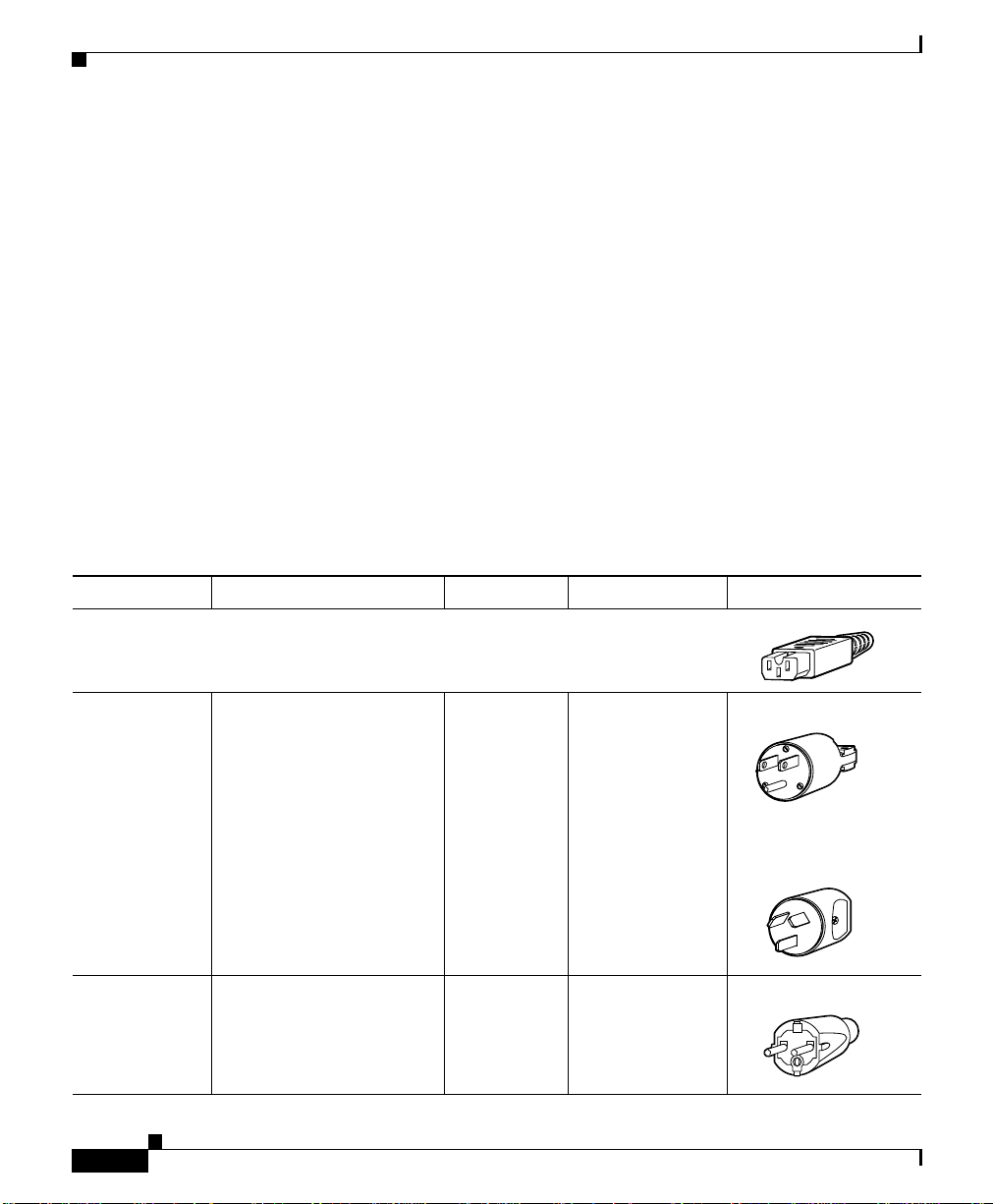
Table 2-1 AC-Input Power Cord Options
Locale Part Number Length Plug Rating Plug Type
Appliance
1000 W Power Supply (PWR-C45-1000AC=)
Coupler
NorthAmerica CAB-7KAC= 8.2 ft (2.5 m) 125 VAC, 15 A NEMA 5-15P
120352
Australia,
New Zealand
Europe(except
Italy)
Catalyst 4500 Series Switches Installation Guide
2-6
120354
CAB-7KACA= 8.2 ft (2.5 m) 250 VAC, 15 A SAA/3,
AS/NZS 3112-1993
120356
CAB-7KACE= 8.2 ft (2.5 m) 250 VAC, 16 A CEE 7/7
120357
78-14409-08
 Loading...