

Page 1

Z-5R Web
www.ironlogic.me
Z-5R WEB Ethernet / Wi-Fi / 3G / 4G network controller
User Manual
1. OVERVIEW
Z-5R WEB Controller is used in Access Control Systems (ACS) to control a single access point.
The controller can work in standalone or network mode.
When in standalone mode, the keys are stored into database by a Master key.
In network mode, external control software is needed to operate the controller and to store keys into
database. The software also allows reading event logs, setting controller time and define valid access time
of the day for each card.
To operate in network mode, the controller is connected to network via Ethernet or Wi-Fi network adapters.
In network mode, if the connection to control software is lost, the controller still continues to work as
standalone, storing the events in the local event buffer.
Authorisation through the access points is made basing on the status of known tokens: proximity cards,
Touch Memory keys, or PIN codes. All these tokens will be hereafter called simply “keys”.
By function, the keys fall into Access keys and Programming keys categories. Access keys, in turn, can be
Normal and Blocking. Blocking keys have more rights than Normal keys.
In Normal mode, the controller grants access to both Normal and Blocking keys.
In Blocking mode, access is granted for Blocking keys, but denied for Normal Keys.
Usage example: all general employees are issued Normal keys, and security department – Blocking keys.
During working hours, the controller is in Normal mode, and all employees are granted access. Out of
hours, Blocking mode is activated and only security has access.
Master keys are the keys that program the controller. They only work for standalone controller
programming, and cannot be used for access.
Master keys allow to:
- Add and erase Normal, Blocking and other Master keys;
- Set time for opening signal on locking device (access control);
- Activate and deactivate Accept Mode.
In Accept Mode, any key is granted access but also is stored into controller memory as a Normal key. This
mode helps to recover the keys database if a new ACS is being installed on a customer site where access
keys have already been issued. In this case, the controller is put into Accept Mode for some time, allowing
it to keep collecting and storing keys into its memory. Then, when the controller is reverted to Normal
mode, only already stored keys will be granted access.
To collect keys codes, the controller supports operation with two readers (one for entry and one for exit) by
Wiegand (-26, -34, -42 or -50), or iButton (Dallas Touch Memory) protocols. Each reader uses its own
separate key database in controller memory. After access is granted to the key, the controller issues a
control signal (opening/closing a transistor) to the locking device (electromechanical or electromagnetic lock
or latch, turnstile or barrier). Locking device type and connection protocol are selected during controller
configuration.
The controller allows storing up to 8,192 events in its circular log buffer. Events include: code gained, door
sensor operated, control signal issued, etc.
To improve functionality the Controller allows to:
- Connect a door sensor to generate “Door passed” event and to reduce the “Door unlocked” alarm
duration (and reducing the locking device unlocked signal duration).
- Connect a door release (“exit”) button to open the door without need for authorisation. Connect an
external emergency unlock signal, so that the door can be opened in emergency.
Page 1
Page 2
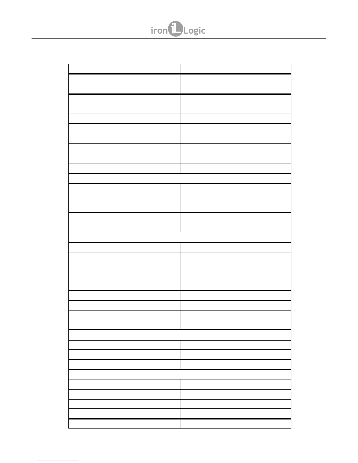
2. SPECIFICATIONS
Keys memory 2x 8168 keys
Events memory 8192 events
Attached readers 2
Reader protocols
Wiegand (-26, -34, -42, -50),
iButton™
Reader indication control Red and Green LEDs, Audible Beep
Readers supply protection 200 mA
Power output current 5 A
ALARM output signal
250 V, 100 mA, 35 Ohm, insulation
1.5 kV
Tamper protection Optical
Ethernet
Interface
RJ45 (10/100BASE-T) Auto
MDI/MDIX
Supported Frame Types Ethernet II, IEEE 802.3
Supported Protocols IP, ARP, TCP, SSH, ICMP, UDP,
DHCP, HTTP
Wi-Fi
Supported Standards IEEE 802.11 b/g/n
Frequency Range 2.4-2.4835 GHz
Transfer Rates 802.11n: up to 150 Mbps
802.11g: up to 54 Mbps
802.11b: up to 11 Mbps
Wireless signal power Up to 20 dBm (100 mW)
Wireless operation modes Access point, Client
Wireless security
64/128/512-bit WEP, WPA, WPAPSK, WPA2, WPA2-PSK
USB
USB Connector type USB Type A
USB Version USB 2.0
USB Mode Host, High Speed, Full Speed
Other Parameters
Weight 150 g
Dimensions, mm 105 x 115 x 37
Mount Wall, 35mm DIN rail (TH35)
Power supply 8 – 28 V
Operational current (at 12V) Up to 300 mA (excluding readers)
Z-5R Web
www.ironlogic.me
page 2
Page 3
116
104
37
32
87
80
99
Z-5R Web
www.ironlogic.me
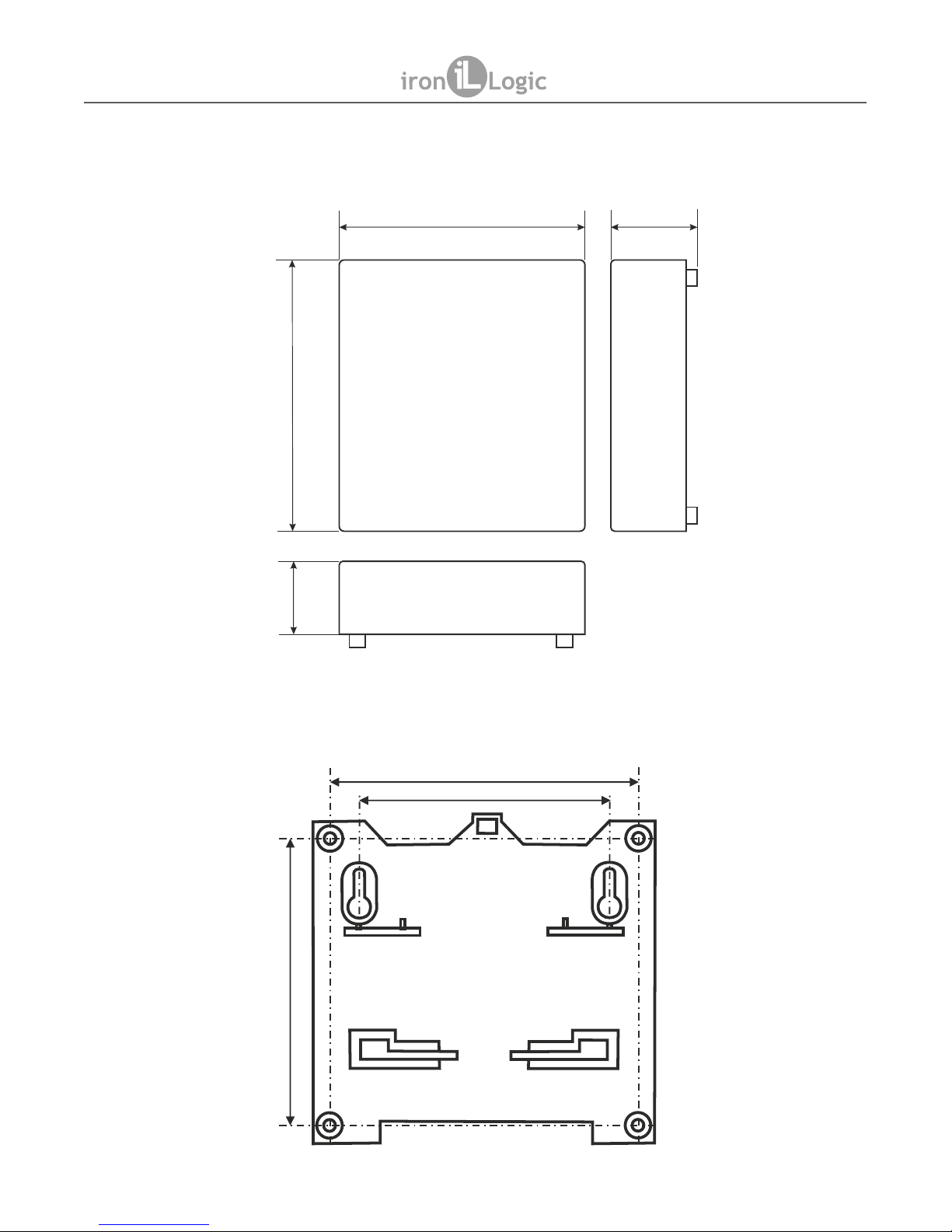
3. CONNECTION
The controller dimensions are presented on this Figure:
Caution: To avoid sharp edges in controller casing, use saw to remove the tabs covering holes for
leading wires through, rather than breaking the tabs out manually.
Dimensions for controller mounting:
page 3
Page 4
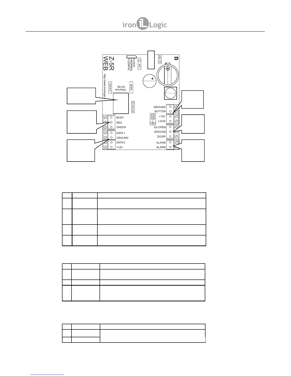
Controller Terminal Layout
Terminals designation table
Power Terminals Group
Sensors Terminals Group
Information Terminals Group
-
socket
Ethernet
No Desig nation Purpose
1 GROUND Connection point for the (-) wire from power supply, and the
second wire from the exit button.
2 BUTTON
Input: Exit button. T his terminal is multi-functiona l and allows
its function to be reassigned.
3 +12V
(+) power supply wire. Also (+) wire from the lock.
4 LOCK
Output: Power output signal. Second (-) wire going to the lock.
The exit is the field-effect transist or dra in.
No Designation Purpose
1 EX.OPEN Input: Evacuat ion mode. Short-circuiti ng this signal to
GROUND switches the Controller into Evacuation mode.
2 GROUND Common (Ground) wire for EX.OPEN and DOOR signals.
3 DOOR Input: Door sensor. When the door is closed, must be short-
ci rcuited to GROUND. This term inal is multi-functional and its
function can be reassigned.
No Designation Purpose
1 ALA RM Output: A reed switch, connecting into security systems as a
part of the security loop.
2 ALA RM
Z-5R Web
www.ironlogic.me
page 4
Block of plugs
of management
of indication
The block of
plugs for
connection of
readers
Block of
power
plugs
Block of
plugs of
sensors
Block of
information
plugs
Page 5
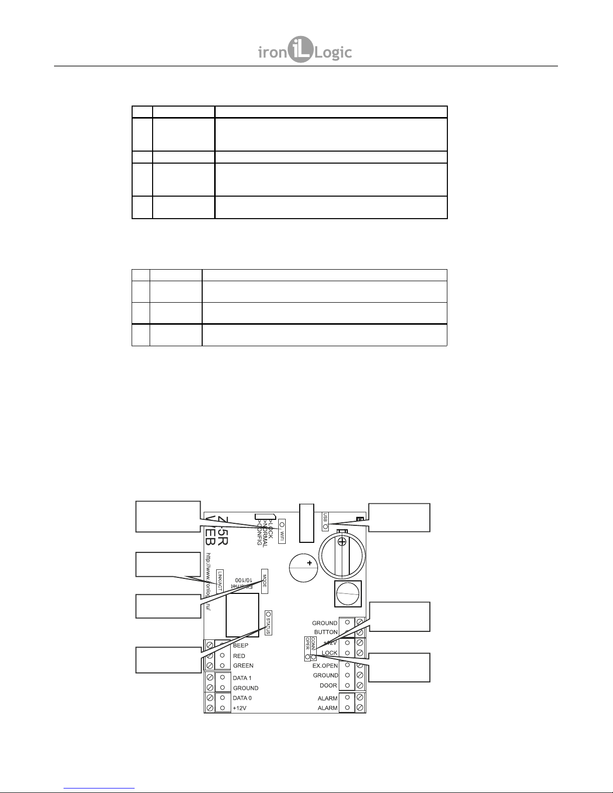
Reader Connection Terminals Group
Reader Indication Terminals Group
Note: Connect both readers by the same protocol! Reader indication control is common for both
readers.
LED Indicators Layout on Controller's PCB
No Designation Purpose
1 DATA1 - Wiega nd mode: DATA1 for reader input and DATA0
for reader output.
- iButton™ mode: reader output signal wire (TM).
2 GROUND Reader common wire connection.
3 DATA0 - Wiega nd mode: DATA0 for reader input and DATA1
for reader output.
- iButton mode: reader input signal wire (TM).
4 +12V Power to readers. Output is protected against short-circuiting
for up to 200 mA.
№ Designation Purpose
1 BEEP
Output signal for management of sound indication of readers. Low
level of a signal is active.
2 RED
Output signal for control of a red LED of readers. The active is the low
level of a signal.
3 GREEN
Output signal for contr ol of a green LED of reader s. The act ive is the
low level of a signal.
Indicator
OPER
Indicator
CONN
Indicator
USB
Indicator
WIFI
Indicator
LINK/ACT
Indicator
MODE
Indicator
STATUS
Z-5R Web
www.ironlogic.me
page 5
Page 6

Indicators Purpose Table:
4. CONFIGURATION
Important:
When configuring Z-5R WEB controller, note that it actually consists of two functional modules:
an ACS controller itself, and a network connection module.
The network connection module allows for:
1) Controller connection to the on-site LAN, via any of the following interfaces: Ethernet, Wi-Fi or
USB modem.
2) Connection to PC running the ACS control software, to manage access control functions
(loading card database, access control management, downloading event logs from buffer etc.)
There are three modes of control software connection:
· Web connection mode. The connection module connects to a control Web server on the
Internet, and the controller is managed via an internal Web site. Example: “cloud” ACS at
www.guardsaas.com .
Designation Colour Purpose
WIFI Blu e Wi-Fi conn ection status:
So lid ON – Wi-Fi network connected.
Blinking ON – data transfer in progress.
USB
Green USB status:
So lid ON – USB device connected.
Blinking ON – data transfer in progress.
LINK/ACT
Green Ethernet connection statu s:
So lid O N – Ethernet physical connection between Z-5R WEB
an d the d evice on the other cable end (usually a switc h).
Blinking – Ethernet packets being received.
MODE
Yellow Control software link status:
So lid ON – TCP link with co ntrol software established.
STA TUS
Red Extern al events:
Flashes – sensor(s) state changed (door, tamper pro tection,
button and emergency unlock), o r key code acquisition.
CONN
Green Connection module status:
Blinking rapidly – connection module no t powered.
Blinking slowly – connection module booting up.
So lid ON – connection modu le active.
OPER
Yellow Requests from control software:
Flashes – the controller is receiving requests from the control
software.
WEB - server
DB
Internet
Internet
Internet
Z-5R
WEB
Z-5R
WEB
Z-5R Web
www.ironlogic.me
page 6
Page 7
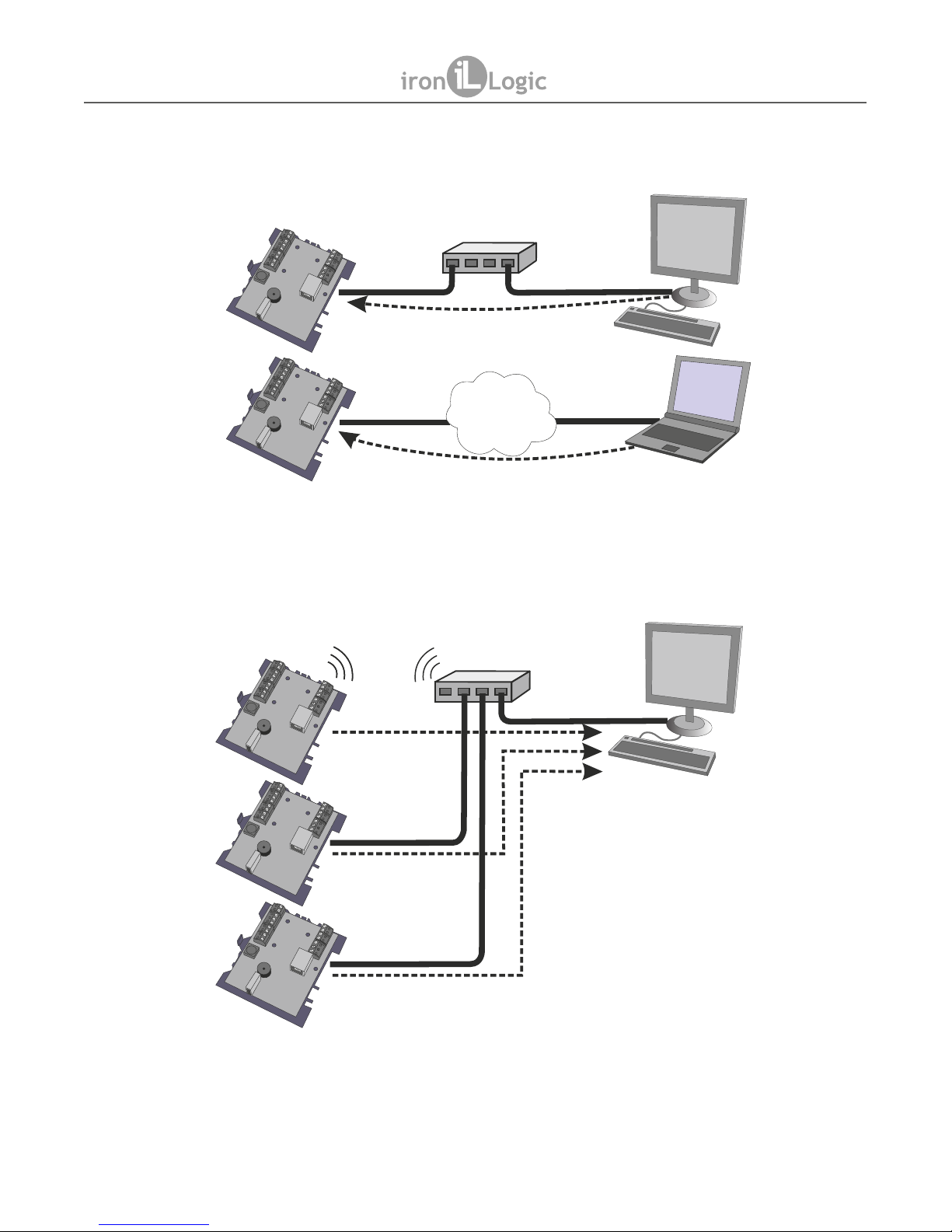
• Server connection mode. The connection module is listening for incoming TCP/IP connections
from the PC running control software (such as GuardLight, GuardCommander, Avantgarde
(Авангард)).
• Client connection mode. The connection module attempts to connect to control software via
TCP/IP. To configure this mode, provide the IP address and port number of a remote PC running the
control software (such as GuardLight, Avantgarde (Авангард), or Zproxy server).
Internet
Ethernet Ethernet
Z-5R
WEB
Z-5R
WEB
Ethernet
Ethernet
Ethernet
Z-5R
WEB
Z-5R
WEB
Z-5R
WEB
Wifi
Wifi
Z-5R Web
www.ironlogic.me
page 7
Page 8

ZProxy Server (available at zproxy.con.ru) allows the (proxied) connection between controller
and the control software, where direct connection is impossible, e.g. if the controller and the
software are in different LANs. If Internet access is available, 1) the controller connects to ZProxy
server, 2) the control software connects to that server too, and 3) using a password, the control
software requests connection to the required controller.
If no connection exists to control software, the controller will work in Standalone mode.
To configure controller functioning mode, use a jumper on the PCB, which can be set as follows:
· CONFIG: on power-up, the controller boots into setup mode, to configure connection
parameters and equipment types.
· NORMAL: Normal mode – the connection module connects to LAN as configured, the
controller makes access control decisions. The existing connection parameters and connected
equipment can be configured at a local IP address.
· LOCK: same operation as at NORMAL. However, both the Web interface for connection
parameters and connected equipment configuration, and data update in Web connection mode, are
locked.
5. WEB INTERFACE
The Web interface is used to configure connection parameters and connected equipment.
You will require a device with a Wi-Fi network connection (smartphone, tablet or notebook),
and an Internet browser (Internet Explorer, FireFox, Opera, Chrome etc.)
Launch the Web interface for controller configuration, via the following sequence:
1. Set on-board jumper into CONFIG position.
2. Power up the controller.
Zproxy
Z-5R
WEB
Internet
>LOCK
>NORMAL
>CONFIG
Z-5R Web
www.ironlogic.me
page 8
Page 9

3. Connect to controller via Wi-Fi or Ethernet.
3.1. Wi-Fi:
3.1.1. Wait until an unsecured Wi-Fi access point with the name Z5WEB_xxxxxx appears.
(can take up to 45 s).
3.1.2. Connect to that unsecured Wi-Fi.
3.2. Ethernet:
3.2.1. Connect a computing device and controller by an RJ-45 Ethernet cable.
3.2.2. Wait until computing device detects a wired LAN connection (can take up to 45 s).
4. Browse to (no authorisation needed).http://1.1.1.1
5. 1. Go through appearing menu tab by tab, and configure parameters on each tab. Please save
the changes on each tab!
Later, when configuration is complete and Z-5R WEB is connected to on-site LAN (on-board
jumper is set into NORMAL or LOCK), the configuration Web interface will still be available by the IP
address which will either be manually assigned during initial configuration, or automatically
acquired from DHCP server when registering onto the on-site LAN.
If the Web interface is activated through the controller IP address, a pop-up authorisation window
will appear. Use “z5rweb” (no quotes) as your login, and for password, the 8 character AUTH_KEY
value found either on the sticker on the back of controller casing, or at the end of this user manual.
Note: The password is case-sensitive – please type exactly as shown.
5.1 Language Selection.
On initial power up, the Web interface is set to work in English. To switch into Russian language,
click the text “Русский” (Russian) in the top right corner of this Web interface.
5.2 5.2. Status Tab.
The Status Tab displays the current controller status.
Z5-R WEB
SN: 50000
Z-5R Web
www.ironlogic.me
page 9
Page 10

LEGEND:
Time Elapsed: time elapsed since the controller powered up.
Connection: LAN connection mode abbreviation (e.g. ETH for Ethernet etc.)
Mode: Controller operation mode (Web, Server, Client, Standalone).
Connected: In Client and Server operation modes, shows IP address of connected PC running the
control software.
Duration: In Client and Server operation modes, shows the current connection duration.
Rx: The number of bytes received during the current connection session.
Tx: The number of bytes transmitted during the current connection session.
Jumper Position: The current jumper position: CONFIG, NORMAL or LOCK.
5.3 Connection Setup Tab
Connection Setup Tab allows setting up the network connection type and connection
parameters. Parameters configuration is similar to those of an Internet router.
5.3.1 Ethernet
If Ethernet connection type is selected, the interface looks as follows:
If a DHCP Server is present on the LAN, all controller network settings can be acquired from it
automatically.
Use DHCP: DHCP server automatically provides IP address and other network parameters
needed to work in this LAN.
No DHCP: Manual network parameters configuration required for this LAN.
Z-5R Web
www.ironlogic.me
page 10
Page 11

Static IP: A unique IP address assigned to the controller.
Network Mask: Subnet mask for this LAN segment.
Default Gateway: IP address of the gateway leading to other networks, including Internet.
DNS Server: The DNS server IP address.
For correct controller operation, all the network parameters must be configured. If you do not
know some of these parameters, please refer to your network administrator.
Save all the settings on this tab by Save button.
5.3.2 Wi-Fi
If Wi-Fi connection type is selected, the interface looks as follows:
SSID: The SSID identifier of the Wi-Fi network to connect to.
Security type: Security type on this Wi-Fi network (WPA, WPA2, None, etc.)
Security key: Security key for this Wi-Fi network.
Network Discovery: Discover available Wi-Fi networks.
IP: Network parameters setup (as for Ethernet connection type described above).
After available Wi-Fi networks are discovered, a dialog box will appear with the list of available
networks, allowing selecting the desired one. Next to each network name, its signal level is given.
Z-5R Web
www.ironlogic.me
page 11
Page 12

To select a network, highlight it in the list and press Select button. When selected, SSID and
security type for that network are displayed in settings area. If network security is enabled, enter the
security key as well.
If no DHCP server exists on the LAN, network parameters must also be set up manually.
After setup is complete, save the parameters by pressing Save button.
5.3.3 3G Modem
If 3G modem connection type is selected, the interface looks as follows:
Where:
Device: A drop-down list of all available modems currently connected to device USB port.
The rest of parameters must be set according to your 3G modem documentation, or obtained
from your mobile operator.
APN: Mobile operator Access Point Name.
Login: Mobile operator Access login.
Password: Mobile operator Access password.
After setup is complete, save the parameters by pressing Save button.
Z-5R Web
www.ironlogic.me
page 12
Page 13

5.3. 4G Modem.
If 4G modem connection type is selected, the interface looks as follows:
Where:
Device: A drop-down list of all available modems currently connected to device USB port.
APN: Mobile operator Access Point Name. Can be found from your 4G modem documentation
or obtained from your mobile operator.
After setup is complete, save the parameters by pressing Save button.
5.4 Control Software Connection Mode Tab
If Z-5R WEB is intended to work in network mode, i.e. under external software control, then after
completing LAN connection configuration, it is also necessary to set up the connection mode
between connection module and control software.
Control Software Connection Mode tab allows to select the connection mode to the control
software.
Where:
Authentication Key: Required when connecting to a cloud-based internet server or when
working via a ZProxy server, and for accessing the controller's Web interface.
Initially this field contains the factory pre-set key, found on a sticker on the back of device casing,
under AUTH_KEY label. If necessary, change the key now. (Only alphanumeric characters
allowed).
Software Connection Mode: Choose Web, Server, Client for network operation, or Standalone
to operate without a control software connection.
5.4.1 Web
Web connection mode provides connection to a cloud SaaS (Security as a Service). To set up,
the following parameters are required from SaaS vendor:
Z-5R Web
www.ironlogic.me
page 13
Page 14

Server Address: DNS name or IP address of the cloud service Web server, where the controller
should connect.
Port: The port on which the cloud Web server is listening.
Path: The path to data processing file on the cloud Web server.
Password: Data access password on the cloud Web server.
Transmission Interval: The interval between connections to the Web server in seconds.
Number of Events: Number of pending controller events that trigger an out-of-sequence data
transmission to Web server, before the current Transmission Interval has elapsed.
After setup is complete, save the parameters by pressing Save button.
5.4.2 Server
In Server connection mode, the connection module is listening for control software connection
on a local port. In this mode, the following parameters need to be provided:
Where:
Local Port: Local TCP port listening for control software connection.
Allowed IP: Source IP address from which control software can connect to controller. (To allow
connections from any IP, use 255.255.255.255 value).
After setup is complete, save the parameters by pressing Save button.
Z-5R Web
www.ironlogic.me
page 14
Page 15

5.4.3 Client
In Client connection mode, the connection module attempts regularly to establish
connection to the control software. Also select this mode, if the controller connects to a ZProxy
server. The following parameters need to be provided:
Where:
Server Address: IP address or name of a server system running the control software, or a ZProxy
server.
Server Port: TCP port on the server listening for connections.
Authentication Key: Necessary to connect to a ZProxy server. The control software passes it
through to ZProxy server, which in turn connects to the controller.
After setup is complete, save the parameters by pressing Save button.
5.4.4 StandaloneThe initial ACS setup, done by jumpers on other controllers, on this
device is performed in Standalone mode. It works with controller keys database via Web
interface, no Master key needed.
Creating and modifying the keys database can thus be done in two ways. First, via Web
interface. Second, using a special Proximity card – a Master key (see below how to program the
controller with Master key).
To fill the key database, the controller needs connected readers. In Standalone mode, both
memory banks are managed simultaneously.
Select Standalone mode to configure keys database via Web interface. The interface looks as
follows:
Z-5R Web
www.ironlogic.me
page 15
Page 16

Where:
Accept Mode: Activates Accept mode, where all new keys will be stored into memory as Normal
keys.
Add Keys Mode: Activates Add Normal and Blocking Keys mode on the controller. See paragraph
7.1 for details.
Add Master Keys Mode: Activates Add Master Keys mode. See paragraph 7.2 for details.
Erase Keys Mode: Erases keys touching the Reader, from the keys database. See paragraph 7.3
for details.
Note: When Add Keys, Add Master Keys or Erase Keys mode is selected, an additional pop-up is
displayed, warning that this mode will automatically be terminated, if the interval between keys
reaches 16 s.
Export Keys to File: Exports the keys database from controller memory into a file on the local
computer running the Web interface.
Browse…: Selects a file on the local computer for subsequent keys import.
Import Keys from File: Imports the (previously exported) file into controller key database. The
previous contents of keys database will be overwritten and lost.
5.5 Controller Setup Tab.
Controller Setup tab allows to set up controller operational parameters.
Lock Type: Electric Latch, Electromagnetic, or Electromechanical.
Readers Protocol: Select key code transmission protocol. For Wiegand protocol, the controller
automatically detects the bit width (26, 34, 42 or 50).
Fire Alarm Input: Enables emergency door unlocking when EX.OPEN input signal is asserted.
Built-in Beeper: Enables/disables the built-in beeper.
Opening Time: Duration of the impulse sent into the lock to unlock the door. Depending on Lock
Type, the impulse can be active-low or active-high.
Opening Check Time: Maximum time after access has been granted till the door is open. The
door opened after this interval is considered Forced. If Opening Check Time is shorter than Opening
Time, -- Opening Time is used for this function.
Closing Check Time: Maximum time while the door stays open. If within Closing Check Time
the door has not closed, a Door Held event is generated into the log. To disable Closing Check, set
this parameter to 0.
After setup is complete, save the parameters by pressing Save button.
Z-5R Web
www.ironlogic.me
page 16
Page 17

5.5.1 Advanced Settings tab.
Advanced Settings tab allows to: export and import configuration to/from a file,
update the controller firmware, reset the controller to factory defaults and reboot the controller:
Export Config to File: Exports the current controller configuration to a file on the local computer
running the Web interface.
Import Config from File: Imports the controller configuration from a file on the local computer
running the Web interface. Select a configuration file first, using Browse… button.
Firmware Update: Updates the controller firmware. Select a file containing the new firmware
first, using Browse… button.
Reset to Factory Defaults: Resets all settings to factory defaults, the current configuration is
overwritten and lost.
Reboot Controller: Reboots the controller to apply the changed network settings.
5.5.2 Ending Web interface operation.
To end working with the Web interface, please change the jumper position from CONFIG to
NORMAL or LOCK, go to Advanced Settings tab and choose the Reboot Controller function there.
6. POWER-UP AND GETTING STARTED.
Connect external devices to your controller as per Chapter 3. Factory default settings for Z-5R WEB
module are as follows:
- Use DHCP server;
- Ethernet connection configuration;
- Wi-Fi protocol disabled;
- Server software connection mode
- Local port: 1000.
Note: It is only possible to change the connection module configuration via Web-interface.
Changing the factory settings is described in Chapter 5 of this manual.
Please set factory settings as required according to selected mode.
- Power OFF the controller.
- Set the jumper to NORMAL or LOCK position.
- Power controller back ON.
- The controller is ready to operate in selected mode.
To use the controller in Standalone mode, launch the Web interface and select Control Software
Connection Mode tab, set the connection mode there to Standalone and create at least one Master
key. Stay in Standalone mode, exit the Web interface and create all Normal keys for access.
Z-5R Web
www.ironlogic.me
page 17
Page 18

7. SETTING UP CONTROLLER WITH A MASTER KEY.
To manage the controller with a Master key (i.e. to switch into required programming mode to
create or erase a Normal or Blocking card, activate Accept Mode, etc.), two types of Master key
touches are used. Short touch is less 1 s, and long touch is about 6 s. In all programming modes,
there is a timeout feature: in 16 s after the last key touch, the controller will leave the programming
mode, emitting four short beeps.
Note 1: The controller contains two keys databases; in Standalone mode, they are filled or
erased in parallel.
Note 2: To use Master key programming, connect your readers via iButton™ protocol.
The following programming modes are possible:
- Add Normal Keys 1 long touch;
- Add Master Keys 1 short touch, 1 long touch;
- Erase Normal Key 2 short touches, 1 long touch;
- Erase All Memory 3 short touches, 1 long touch;
- Set Door Opening Time 4 short touches;
- Activate Accept Mode 5 short touches;
- Deactivate Accept Mode 1 short touch.
7.1 Add Normal Keys Mode.
Touch and hold the reader with a Master key. The controller will emit a short beep
acknowledging the Master key, and in 6 s, one more beep indicating that controller has switched
into Add Normal Key mode. Take the Master key away from the reader.
To add new Keys, keep touching the reader with them, one after another, ensuring that interval
between touches does not exceed 16 s. The reader will acknowledge each new touch by a short
beep.
Hold a new key at the reader for 3 s and more, for it to be written as a Blocking key (otherwise
Normal key).
If the presented key already exists in memory, the controller will emit two short beeps.
To exit this mode, either wait 16 s after last key touch, or touch the reader with a Master key. The
controller will acknowledge exit from programming by four short beeps.
7.2 Add Master Keys Mode
Touch the reader shortly with a Master key. The Controller will emit a short beep
acknowledging the Master key. No later than 6 s after that, touch and hold the Master key at the
reader. The controller will emit two short beeps denoting second Master key touch in programming
mode, and in 6 s, -- one beep denoting that controller switched into Add Master Keys mode. Now
take the Master key away from the reader.
To add new Master keys, keep touching the reader with them, one after another, ensuring that
interval between touches does not exceed 16 s. The reader will acknowledge each new touch by a
short beep, however if the presented key already exists in controller memory, there will be no
signals.
To exit this mode, wait 16 s after last key touch. The controller will acknowledge exit from
programming by four short beeps.
Z-5R Web
www.ironlogic.me
page 18
Page 19

7.3 Erase Normal Keys Mode
Touch the reader shortly twice with a Master key. The controller will emit a short beep
acknowledging the Master key. On second touch, the controller will emit two short beeps denoting
second Master key touch in programming mode. No later than 6 s after that, touch and hold the
Master key at the reader (long touch). On third touch, the controller will emit three short beeps and in
6 s, one beep denoting switch into Erase Normal Keys mode. Now take the Master key away from
the reader.
To erase Normal and Blocking keys, keep touching the reader with them, one by one, ensuring
that the interval between touches does not exceed 16 s.
On each touch, successful erasing a key will be acknowledged by a short beep; if a key did not
exist in memory, two beeps will follow.
To exit this mode, either wait 16 s after last key touch, or touch the reader with a Master key. The
controller will acknowledge exit from programming by four short beeps.
7.4 Erase All Memory Mode.
Touch the reader shortly three times with a Master key. The controller will emit a short beep
acknowledging the Master key. On second touch, the controller will emit two short beeps, denoting
the second Master key touch in programming mode. On third touch, the controller will emit three
short beeps denoting the third Master key touch. No later than 6 s after that, touch and hold the
Master key at the reader (long touch). On fourth touch, the controller will emit four short beeps, and
in 6s a series of short beeps denoting controller memory erase and automatic exit from
programming mode.
Now you can take the Master key away from the reader.
Note: When keys database is being erased via the Master key, the existing programmed Lock
Opening Time setting is not erased.
7.5 Set Lock Opening Time.
Touch the reader shortly four times with a Master key. On each touch, the controller will
acknowledge the Master key, emitting as many short beeps as the number of touch (one for first
touch, two for second etc.). On fourth touch, the controller will emit four short beeps and will switch
into Lock Opening Time programming mode.
No later than 6 s after that, please press and hold the door release button for the length of time
required for opening. When the door button is released, the controller will emit a beep and set the
time which the button was pressed, as the new door opening time.
For exact time programming, we recommend using the Web interface.
7.6 Accept Mode.
Use the Accept mode to store all keys touching the reader into memory. Any key touching the
reader will unlock the door and be stored into controller memory if it does not exist there yet.
This mode is used for controller keys database recovery without having to gather back all the
keys issued to users. A Master key is necessary to activate this mode.
Touch the reader shortly five times with a Master key. On each touch, the controller will
acknowledge the Master key, emitting as many short beeps as the number of touch (one for first
touch, two for second etc.). On fifth touch, the controller will emit five short beeps and in a few
seconds, a long beep, which acknowledges Accept mode activation.
To deactivate Accept mode, touch the reader with a Master key again; a series of short beeps will
acknowledge the exit from this mode.
Note: If the supply power fails while Accept mode is active, it remains active after the power is
back on.
Z-5R Web
www.ironlogic.me
page 19
Page 20

7.7 Access Modes.
The controller supports three access modes.
1) Normal Access: both Normal and Blocking keys grant access.
2) Blocking: only Blocking keys grant access.
3) All-Pass: the lock stays unlocked.
The Blocking and All-Pass modes are activated with a Blocking key (see 7.1. on how to add one),
by touching and holding it at the reader for 3 s or longer (long touch). If the door was open during this
sequence, the All-Pass mode is activated, and if it was closed, the Blocking mode. If Blocking or AllPass mode is already active, the same action deactivates it and Normal Access mode is restored.
Note: When using a Blocking key, the access is granted at the moment when the key is removed
away from the reader.
In Blocking mode, when a Normal key is used, access is denied and this fact is acknowledged by
a series of short beeps.
In All-Pass mode, all keys that have touched the reader, are registered in memory for further
processing by control software.
Note: If the supply power fails while Blocking mode is active, it remains active after the power is
back on.
8. CONNECTION OF NETWORK AND STANDALONE MODES.
Note 1: When the power is back after a power failure, the Controller remains in the mode that was
active before the failure. Exception: Add/Erase Keys modes do not persist after power is back on,
but normal operation mode is reactivated instead.
Note 2: When switching from standalone mode to network mode, the control software usually
overwrites existing keys database with the new keys database from the control computer.
Therefore, we recommend saving existing keys database before connecting the controller to
control software, so it can later be restored, or exported into control software.
Note 3: If while in network or Web mode, a Master key is presented to the controller, most probably
nothing happens, because the network software removes all existing Master keys and forbids
creating new keys. To enter a new key into networked system while in network mode, use the control
software.
Note 4: If after the controller is configured in standalone mode, it will need to be accessed via
software (e.g. Guard Commander) over the network, then please use the Web interface to configure
the controller for network operation.
9. PACKAGE CONTENTS.
- Z-5R WEB controller -1
- Mounting kit -1
- CR2032 (watch-type) battery -1
10. OPERATING CONDITIONS
Ambient temperature: 5°C…40°C
Humidity: Not exceeding 80% at 25°C
The reader should not be operated where the following exists: atmospheric precipitation, direct
sunlight, sand, dust and moisture condensation.
Device specifications may not fully be as specified, when operating under non-recommended
conditions.
Z-5R Web
www.ironlogic.me
page 20
Page 21

page 21
11. LIMITED WARRANTY.
This device is covered by a limited warranty for 24 months.
The warranty becomes void if:
- This Manual is not followed;
- Device has physical damage;
- Device has visible traces of exposure to moisture and aggressive chemicals;
- Device circuits have visible traces of being tampered with by unauthorised parties.
Under active warranty, the Manufacturer will repair the device or replace any broken parts,
FREE of charge, if the fault is caused by manufacturing defect.
12. IRONLOGIC CONTACTS
Headquarters:
RF Enabled ID Limited
34 Ely Place, London, EC1N 6TD, UK
E-mail: marketing@rfenabled.com
Development and production:
AVS LLC
7, Bobruiskaya street, Saint-Petersburg, 195009, Russian Federation
E-mail: marketing@rfenabled.com
Phone: +78122411853; +78125421185
www.ironlogic.ru
Authorized representative in the European Union:
SIA IRONLOGIC
79A, Slokas iela, LV-1007, Riga, Latvia
E-mail: info@ironlogic.lv, headstaff@ironlogic.lv
Phone: +37166181894; +37124422922
www.ironlogic.me
Z-5R Web
www.ironlogic.me
The symbol of crossed-throught waste bin on wheels means that the product
must be disposed of at f separate collection point. This also applies to the product
and all accessories marked with this symbol. Products labeled as such must not
be disposed of with normal household waste, but should be taken to a collection
point for recycling electrical and electronic equipment. Recycling helps to reduce
the consumption of raw materials, thus protecting the environment.
 Loading...