

Page 1

1. OVERVIEW
Z-395 EHT electronic lock is a contactless reader combined with a standalone controller and
electromechanical lock. The lock is powered by four AA type batteries. Compact, with five
operational modes, easy in installation, programming and servicing, this lock is a perfect access
control solution for various storage places: gym lockers, changing cabins, office furniture, trade
equipment. Particularly broad application of these locks happens in places like SPA, water
parks, gyms, swimming pools.
A Z-395 EHT lock can be installed as a standalone device, or as a part of a complex access
control solution. For access keys, it accepts contactless key fobs and bracelets. Z-395 EHT can
operate in five different modes:
- Gym Mode: keys are not tied to locks. Any key can open and close any free locker.
- Logic Mode: keys are not tied to locks. Any key can open and close any free locker. The
number of used locker and battery levels are stored into keys. This is convenient when the user
forgets which locker he used. Can set the maximum for the number of lockers per one user
(range 1 to 15). Computerized logging and lock setup. Only works with Lock Manager software.
- General Mode: a typical lock controller operation: only the key(s) stored in the lock's
memory (maximum 24) can open that lock.
- Safe Deposit Box Mode: the lock emulates safe deposit box operation. To open the lock, all
the keys in controller database (max. 26) must be swipe to it, one after another.
- Custom Mode: you can design your own custom operational logic, subject to your needs.
Then obtain updated firmware from the Manufacturer and download it into the lock with
an RF-1996 adapter.
Programming of operational modes, Master and User cards, is done via Reset button on the
lock's case (see Chapters 4 to 11) or via Lock Manager software using an RF-1996 adapter
(see Chapter 12). Selected modes and cards database are stored in the lock's NVRAM (nonvolatile memory).
After one of the modes selected and all configuration done, the lock starts to work according to
these rules:
On key swipe to the lock's reader,
- if the token has access granted, a beep sounds and the LED flashes green, or else
- if the token has access denied, a beep sounds and the LED flashes red.
Z-395 EHT
www.ironlogic.me
Z-395 EHT RFID Electronic Furniture Lock
with EM-Marine & HID ProxCard II & Atmel (T5557) reader (125 kHz)
and standalone controller
User Manual
page 1
Page 2
page 2
Z-395 EHT
www.ironlogic.me
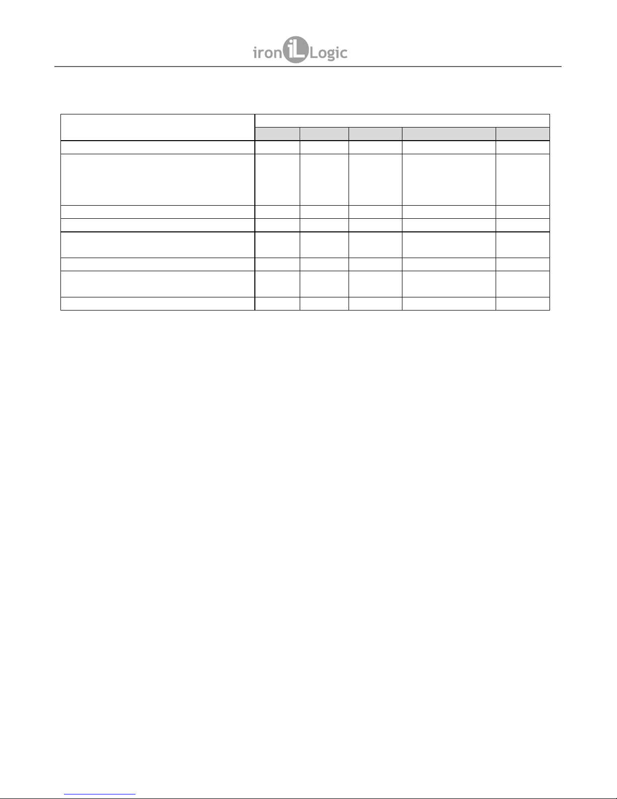
Z-395 EHT Electronic Lock Operational Modes Comparison Table.
Features Operational Modes
Gym
Logic*
General
Safe Deposit Box
Custom
Any key can open/close any locker + + +
Limit on lockers number that can be taken
by one bracelet. The operator defines the
maximum lockers number for one bracelet
(1…15)
+ +
Logging of free/taken lockers currently + +
Logging the gym attendance times + +
Information Kiosk (tells the client their
locker number,if forgotten)
+ +
Battery charge level recorded into bracelet + +
Encryption, protection against bracelet
cloning
+ +
Locks setup and further use without a PC + + + +
* Note:Logic Mode requires special Atmel (T5557) keys and Lock Manager software.
2. SPECIFICATIONS
- Working Frequency: ............................................................................................... 125 kHz;
- Keys standards: ............................................EM-Marine, HID ProxCard II, Atmel (T5557);
- Maximum number of keys: .................................................................Normal - 26; Master - 4;
- NVRAM to store settings: .........................................................................................Present;
- Reading distance: ..................................................................................................2…4 cm;
- Standby consumption current: ...............................................................................30 (mkA);
- Audio-visual status indication: .........................................................buzzer, bicoloured LED;
- Working temperature range: .............................................................................+5…+40 °C;
- Case material: .......................................................................................metal, ABS plastic;
- Dimensions, mm:
- External module ...................................................................................................47 x 35;
- Internal module ...........................................................................................145 x 63 x 21;
3. MOUNTING
To mount the lock, you will require:
1. Drill;
2. Ø35mm spade drill bit (to mount onto wooden furniture);
3. Phillips screwdriver;
4. Hex 2.5 mm socket wrench;
Page 3
page 3
Z-395 EHT
www.ironlogic.me
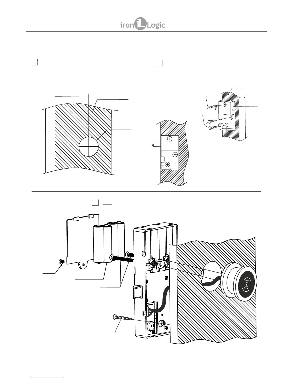
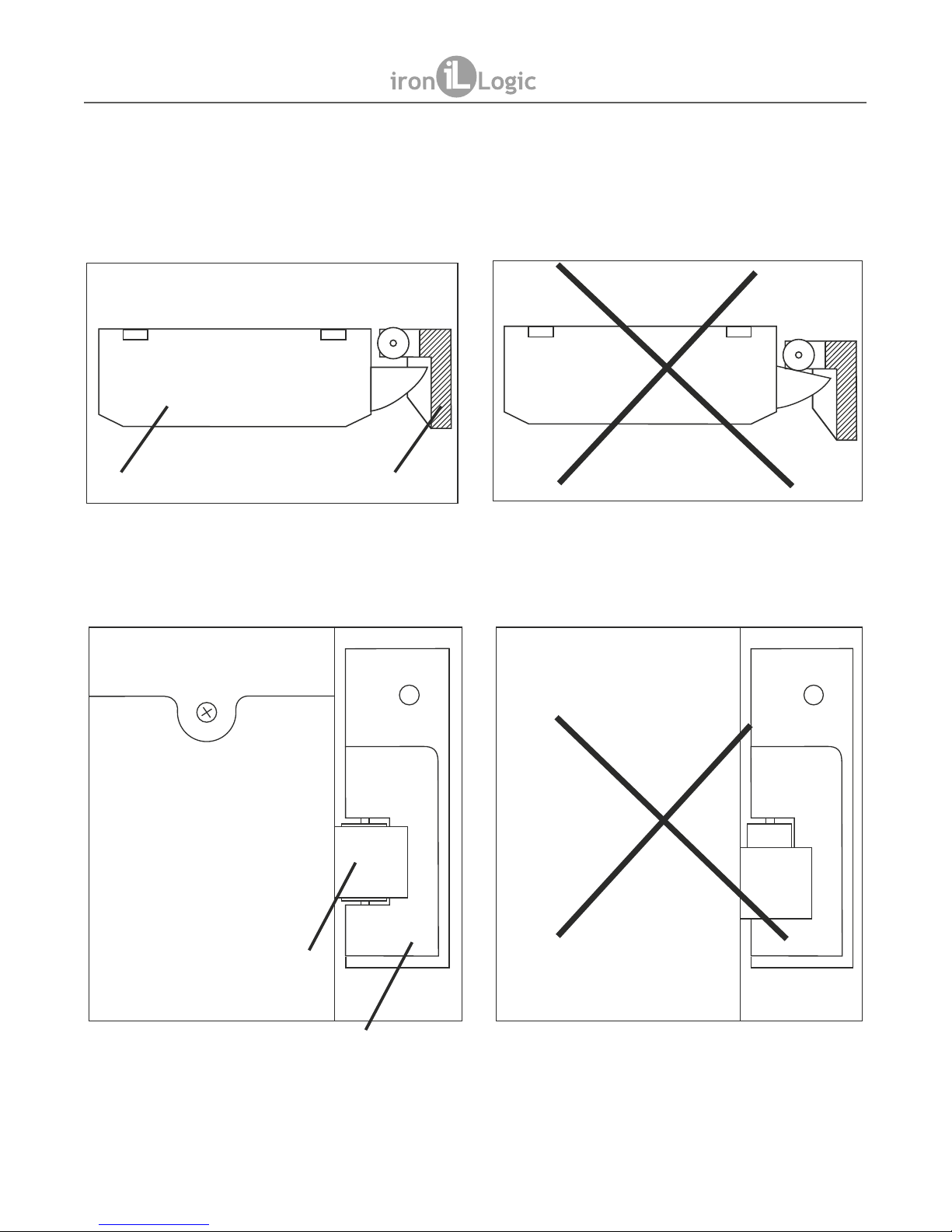
Installation onto a wooden (chipboard) locker
www.ironlogic.ru
2
3
1
Make a 35 mm hole in the locker's door. To mark the hole position
use template from Fig. 13.
Locker's door
Ø 35,0
Fig.1
Install the lock's push bolt unit onto the locker's wall (see Fig. 3,
4). To mark the hole positions, use template from Fig. 13.
Fig.3
Fig.4
Self-tapping Screw
3,5х15
locker's wall
Self-tapping Screw
3,5х25
push bolt unit
Fig.2
A - the calculated size, depends on
thickness of the locker's wall
A
Connect cable to lock's PCB.
Note: Check that cable socket is firmly connected with lock's PCB
socket. Install the locking module according to Fig. 2.
Batteries AA size 1,5V
Self-tapping Screw 4х35
Screw 3х6
Screw 4х30
Page 4
page 4
Z-395 EHT
www.ironlogic.me
How to install the Z-395 EHT lock properly
Top view
View from inside the door
Lock's latch
push bolt unit
push bolt unit
Lock
Page 5

page 5
4. INITIAL POWER-UP, ADDING MASTER KEYS BY RESET BUTTON
Initial power-up sequence (No keys in lock's memory)
- Connect the reader module to the lock module by a supplied cable.
- Insert four AA batteries.
- Swipe the reader by any EM-Marine key.
- The controller issues audible and visual signals.
- Device is ready for operation.
Note: For consistent reader operation, keys with label diameter 15…35 mm are recommended.
To add a Master key, perform the following steps:
- Disconnect the power (take out one of the batteries or use the external power supply switch, per
Fig. 10);
- Push and hold the RESET button with a sharp tool (hairpin, toothpick, straightened paper clip
etc.)
- Connect the power (re-insert the battery, or use the external power supply switch again, per Fig.
10), and only after that release the RESET button;
- Within 5 s after this, push and hold RESET button again;
- Swipe up to 4 keys to promote to Master one by one still holding RESET down;
- Release RESET button. In 6 s, both audible and visual signals will confirm exit from the Add
Master Key mode.
5. SELECTING AND SETTING OPERATIONAL MODE BY RESET BUTTON
Note: Cannot select operational mode without a Master key.
The lock supports four pre-customised operational modes:
- Gym mode: allows not to tie up the key to the lock. The user chooses which of the available
lockers to use.
- Logic mode: allows recording the used locker number and battery level into the key
(bracelet). Very convenient when the user forgets which locker he used. Allows not to tie up the key
to the lock. The user will decide which of the free lockers to use. Works only with Lock Manager
software.
- General mode: traditional lock controller operation: only the keys recorded in lock's database
can open the locker;
- Safe Deposit Box mode: safe deposit box mode emulation. To open the lock, all the keys in
lock's database need to be presented to the lock, one after another.
In addition to the above modes you can order your own Custom mode, which will be designed
according to your needs.
At factory settings, Gym mode is pre-selected by default. It is activated straight after the Master
key(s) have been added. To select a different operational mode, follow these steps:
- Disconnect the power (take out one of the batteries or use the external power supply switch, as
per Fig. 10);
- Press and hold the RESET button with a sharp tool.
- Connect the power (reinsert the battery, or use the external power supply switch, as per Fig. 10),
and only after that release the RESET button;
- Press the RESET button shortly (once). The lock issues audible and visual signals twice. The
lock is now in Logic Mode;
- Press the RESET button shortly (once). The lock issues audible and visual signals three times.
The lock is now in General Mode;
- Press the RESET button shortly (once). The lock issues audible and visual signals four times.
The lock is now in Safe Deposit Box Mode.
Z-395 EHT
www.ironlogic.me
Page 6

- Press the RESET button shortly (once). The lock issues audible and visual signals once. The
lock is now in Gym Mode again.
- To confirm the selected mode, do nothing for 6 s. After 6 s, audible and visual signals
acknowledge the exit from the Operational Mode selection.
6. GYM MODE
Note: Cannot select an operational mode without a Master key.
Rules of operations for Gym mode:
1. Opening the lock is possible with the key recorded when door was locked.
2. Locking is only possible when the lock is open (latch hidden within the lock);
3. Swipe the key to the reader. If it is valid, the lock is now armed (latch pops out, beep sounds
and the LED flashes green);
4. After the lock is armed, the user can put his possessions inside and close the door.
5. While the lock is armed (door is closed), the LED flashes red, showing that this locker is
occupied.
6. If a key not recorded in memory is swiped to the reader, a beep sounds and the LED
flashes red.
7. If a correct key is swiped to the reader, a beep sounds and the LED flashes green. The key
is erased from lock's memory, the latch is withdrawn inside the lock. The door is now open, lock
is ready to restart the cycle from the beginning.
Legend:
. - beep once, - multiple beeps, G - Green LED, R - Red LED, “blink” - blinking.
page 6
Z-395 EHT
www.ironlogic.me
Action
Sound
LED
Latch
What for
Default state None None OUT if a Normal
key is in memory,
Otherwise IN
Waiting for Normal key assignment
Swipe a key
G OUT Storing the key into the controller
(“armed”), lock can be closed
Swipe another key R blink IN Indicates wrong key
Swipe the recorded
key
G IN Erasing key from controller, lock is
waiting for Normal key assignment
Master key override, KEEPING the Normal key in the database
Door closed, swipe
Master key
R blink IN Master key override: opening the
locker
Within 10 s, swipe
Master key 2nd time
R blink OUT Master key override: closing back the
locker, Normal key still stored in
database
Master key override, ERASING the Normal key from the database
Door closed, swipe
Master key
R blink IN Master key override: opening the
locker
Wait 10 s, do
nothing
R blink IN Master key override: erasing Normal
key from database. Standby for a
Normal key assignment.
Page 7

7. LOGIC MODE
Note: Cannot select an operational mode without a Master key.
Logic mode can only work with Lock Manager software and RF-1996 adapter.
Logic mode can also only work with Atmel (T5557) keys.
Additional Information about Logic mode operation can be found on the ironlogic.me website.
Rules of operations for Logic mode:
1. Opening the lock is possible with the key recorded when door was locked.
2. Arming the lock is only possible if the lock is currently open (the latch is INSIDE the lock);
3. Swipe the key to the reader. If it's valid, the lock becomes armed (latch pops OUT, beep
sounds and the LED flashes green).
4. While arming the lock, it records the locker number and batteries charge level into the key.
5. After the lock is armed, the user can put his possessions inside the locker and close the door.
6. While the lock is armed (door is closed), the LED flashes red, showing that the locker is
occupied.
7. Swipe the correct key to lock's reader, then a beep will sound, green LED will flash, the
key will be erased from the lock's memory, the latch will be draw inside the lock. The door is
now open, lock is ready to restart the cycle from the beginning.
page 7
Z-395 EHT
www.ironlogic.me
Action
Sound
LED
Latch
What for
Default state None None OUT if a locker
is occupied,
otherwise IN
Waiting for Normal key assignment
Swipe a key
G OUT Locker number and battery charge gets
stored into the key, the lock can be closed
Swipe another key G blink IN Indicates wrong key
Swipe the recorded key G IN Opening the lock, the locker number and
battery charge gets stored into the key.
Master key override, KEEPING the Normal key in the database
Door closed, swipe
Master key
R blink IN Master key override: opening the locker
Within 10 s, swipe
Master key 2nd time
R blink OUT Master key override: closing back the
locker, Normal key still stored in database
Master key override, ERASING the Normal key from the database
Door closed, swipe
Master key
R blink IN Master key override: opening the locker
Wait 10 s, do nothing
R blink IN Normal key erased from database.
Standby for next Normal key assignment.
Page 8
page 8
8. GENERAL MODE
Note: Cannot select an operational mode without a Master key.
Rules of operations for General mode.
1. Opening the lock is possible by the key recorded in lock's memory.
2. On 1st key swipe to lock's reader, the latch comes OUT, a beep sounds and the LED
flashes green, the user can now put their possessions inside and close the door.
3. On 2nd key swipe to lock's reader, the latch gets drawn IN, a beep sounds and the LED
flashes green, now the door is open again.
4. If a key not present in lock's memory is swiped, a beep sounds and the LED flashes red.
Z-395 EHT
www.ironlogic.me
Action
Sound
LED
Latch
What for
Add Normal Keys
Default state None None IN or OUT Waiting for Normal key to be stored
Swipe Master key 1st
time
R blink IN Entering Edit Normal Keys mode
Swipe Master key 2nd
time
R blink OUT Entering Edit Normal Keys mode
Swipe Master key 3rd
time for 6 s
R IN Entering Edit Normal Keys mode
Swipe 1st, 2nd, 3rd, …, Max
(26th) keys
G IN Recording Normal Key into the controller
Swipe Master key R blink OUT
Exiting Add Normal Keys mode
After 5 s R blink OUT
Erase All Normal Keys
Default state None None OUT Waiting for Normal key written
Swipe Master key 1st
time
R blink IN Entering Edit Normal Keys mode
Swipe Master key 2nd
time
R blink OUT Entering Edit Normal Keys mode
Swipe Master key 3rd
time for 6 s
R IN Entering Edit Normal Keys mode
Press button once R OUT Erase All Normal keys
Swipe Master key R blink OUT
Exiting Erase All Normal Keys mode
After 5 s R blink OUT
Master key override
The door is closed. Swipe
Master key
R blink IN Master key override, locker opening
Wait 5 s R blink OUT Default state
Page 9

page 9
9. SAFE DEPOSIT BOX MODE
Note: Cannot select an operational mode without a Master key.
Rules of operations for Safe Deposit Box mode.
1. The latch is always released (OUT), if the database is not empty;
2. Opening the lock is possible by swiping ALL the keys to the reader, one after another.
3. After all keys have been presented, a beep sounds and the LED flashes green, the lock's
latch is withdrawn for 3 s and then is popped back out. If the door was locked, it's opened
by a lock's push bolt.
4. If a key not present in memory is swiped, a beep sounds and the LED flashes red.
Z-395 EHT
www.ironlogic.me
Action
Sound
LED
Latch
What for
Add Normal Keys
Default state None None OUT Waiting for Normal key recording
Swipe Master key 1st time R blink IN Entering Edit Normal Keys mode
Swipe Master key 2nd time R blink OUT Entering Edit Normal Keys mode
Swipe Master key 3rd time
for 6 s
R IN Entering Edit Normal Keys mode
Swipe 1st, 2nd, 3rd, …, Max
(24th) keys
G IN Storing Normal Key into the controller
Swipe Master key R blink OUT
Exiting Add Normal Keys mode
After 10 s R blink OUT
Erase All Normal Keys
Default state None None OUT Waiting for Normal key written
Swipe Master key 1st time R blink IN Entering Edit Normal Keys mode
Swipe Master key 2nd time R blink OUT Entering Edit Normal Keys mode
Swipe Master key 3rd time
for 6 s
R IN Entering Edit Normal Keys mode
Press button once R OUT Erase All Normal keys
Swipe Master key R blink OUT
Exiting Erase All Normal Keys mode
After 10 s R blink OUT
Master key override
The door closed, swipe
Master key
R blink IN Master key override, locker opening
Wait 10 s R blink OUT Default state
Page 10

page 10
10. ERASING OF ALL MASTER KEYS
This function erases all Master keys from lock's database, leaving only the Normal keys intact.
Also cancels the currently selected operating mode.
To erase all Master keys, please perform the following steps:
a. Disconnect the power (remove one battery or use the switch on external power source,
see Fig. 10);
b. Push and hold the RESET button using any sharp tool;
c. Connect the power (re-insert the battery or use the switch on external power source, see
Fig. 10); continue to hold down the RESET button for 6 s until the beep and visual signal
that will acknowledge that all Master keys have now been erased.
d. After all Master keys have been erased, please record at least one Master key into lock's
memory, so that an operational mode can be selected.
Note: Cannot choose an operational mode without a Master key!
11. RESET TO FACTORY DEFAULTS
This function resets the lock into initial (factory) state. All Master and Normal keys are erased,
the currently selected operational mode is cancelled.
To reset to factory defaults, please perform the following steps:
a. Disconnect the power (remove one battery or use the switch on external power source,
see Fig. 10);
b. Push and hold the RESET button using any sharp tool;
c. Connect the power (re-insert the battery or use the switch on external power source, see
Fig. 10); continue to hold down the RESET button for 16 s. The beep and visual signal will
appear at 6 s and 16 s from the moment the RESET button was pressed down. The beep
and visual signal at 16 s will confirm that the device is now reset to factory defaults.
12. PROGRAMMING USING RF-1996 ADAPTER AND LOCK'S MANAGER SOFTWARE
Lock's Manager software along with RF-1996 adapter takes care about configuration, set up
and further operations of electronic furniture locks.
Lock's Manager software comprises two modules:
- Edit Module: free module that configures and sets up electronic furniture locks and keys for
further operations.
- Manager Module: module that takes care about day-to-day site operation. Manages keys
and records attendance, monitors staff operations, provides periodic reports, monitors the
used lockers numbers, provides the user info-kiosk function (will remind the user the locker
number in case they forgot), controls the battery levels in the locks, protects against
fraudulent card cloning. Works only in Logic Mode and with Atmel (T5557) keys.
Programming works as follows:
- Install Edit Module onto a laptop (required, so it can be taken to every lock on site for
programming).
- Connect an RF-1996 adapter to the laptop.
Select operational mode
- Record a Master card.
- Swipe the RF-1996 adapter to the lock's reader, to record the selected operational mode and
Master card into that lock via contactless technology. The transmission takes 2…3 s after
the laptop has been connected to the lock.
Detailed instructions for Lock's Manager software and RF-1996 adapter can be found on the
ironlogic.me website.
Z-395 EHT
www.ironlogic.me
Page 11

page 11
13. BATTERY DISCHARGE INDICATION AND REPLACEMENT
With 1,500 mAh alkaline batteries, the lock is guaranteed to open at least 10,000 times, or
to work 2.5 years in stand-by mode.
The lock controls the battery charge and informs the users that batteries need to be
replaced.
- Batteries need replacing.
If on Normal key swipe, the LED is not flashing, but the lock is still working it means that
lock's batteries are almost totally discharged and need replacing. If the batteries could not
be timely replaced and the lock lacks energy to open the locker, please use external power
module (power the lock via the connector present on the reader) and swipe the lock with
the key (see Fig. 10)
- Batteries are fully discharged.
If on Normal key swipe, the LED is not flashing AND the lock's latch doesn't pop out it
means that lock's batteries are fully discharged.
In Logic mode, the lock records the current battery charge level into the token, on each
lock opening.
- Batteries replacement.
The lock's electronics include NVRAM for lock settings and keys, so they are not lost after
batteries replacement. To replace the lock's batteries, please see Fig. 11.
Z-395 EHT
www.ironlogic.me
Fig.11
Fig.10
External
power
module
OFF-ON
Page 12

page 12
15. ADDITIONAL ACCESSORIES
Detailed information about all additional accessories can be found on the ironlogic.me website.
- Metallic lock cover (NAM2)
Snaps onto the internal part of the lock. Provides attractive appearance and anti-vandal
protection.
- External power module
Provides power for locks. Convenient when programming the locks' operational mode. Used to
provide power to the lock, if the batteries are completely discharged and the lock is closed.
- Bracelets (identifiers)
- Lock module for lockers
A spare lock module without electronics, for replacement or repairs.
- RF-1996 adapter
Used to set up the locks from the portable computer and subsequent bracelets programming.
- LOCK'S MANAGER software
Used to set up the locks from the portable computer and subsequent bracelets programming.
16. OPERATING CONDITIONS
Ambient temperature: +5…+40°C.
Humidity: ≤ 98% at 25°C.
When operating under non-recommended conditions, device parameters can deviate from
specified values.
17. LIMITED WARRANTY.
This Device is covered by limited warranty for 24 months since the purchase date.
The warranty becomes void, if:
- this Manual's guidelines are not followed;
- the device has suffered physical damage;
- the device has visible traces of exposure to moist and/or aggressive chemicals;
- the device circuits have visible traces of tampering by unauthorised parties.
Under this warranty, the Manufacturer shall repair the device or replace any broken parts as
required, free of charge, in cases where the fault is caused by a Manufacturer's defect.
18. PACKAGE CONTENTS
- Lock module: ..................................1;
- Reader module: ..............................1;
- Battery compartment cover: ...........1;
- Cable with connectors: ...................1;
- Push bolt unit: .................................1;
- Fixing set: .......................................1.
Z-395 EHT
www.ironlogic.me
Page 13
page 13
19. IRONLOGIC CONTACTS
Headquarters:
RF Enabled ID Limited
34 Ely Place, London, EC1N 6TD, UK
E-mail: marketing@rfenabled.com
Development and production:
AVS LLC
7, Bobruiskaya street, Saint-Petersburg, 195009, Russian Federation
E-mail: marketing@rfenabled.com
Phone: +78122411853; +78125421185
www.ironlogic.ru
Authorized representative in the European Union:
SIA IRONLOGIC
79A, Slokas iela, LV-1007, Riga, Latvia
E-mail: info@ironlogic.lv, headstaff@ironlogic.lv
Phone: +37166181894; +37124422922
www.ironlogic.me
The symbol of crossed-throught waste bin on wheels means that the product
must be disposed of at f separate collection point. This also applies to the product
and all accessories marked with this symbol. Products labeled as such must not
be disposed of with normal household waste, but should be taken to a collection
point for recycling electrical and electronic equipment. Recycling helps to reduce
the consumption of raw materials, thus protecting the environment.
Z-395 EHT
www.ironlogic.me
Page 14

Holes Layout for Z-395 EHT installation onto a wooden (chipboard) locker.
Locker`s wall
47
35
mm
Locker`s door
Fig.13
A* -- the size is calculated, depending
on locker chipboard wall thickness.
A*
Z-395 EHT
www.ironlogic.me
page 14
 Loading...