

Page 1

1. OVERVIEW
Matrix II MF-I RFID reader is used in Access Control Systems (ACS) to acquire codes from
approached Mifare tokens (cards, key fobs, bracelets etc.) and transmit them to controllers via
iButton (Dallas Touch Memory) or Wiegand protocols.
A distinctive feature of this model is the support of IronLogic Protected technology, to reliably protect
cards against cloning (see more details on www.ironlogic.me website). This technology, in addition
to a Matrix II MF-I RFID reader requires: a Z-2 USB MF Desktop reader (with modified firmware),
IronLogic Object Card(s) and Mifare cards or key fobs to make access cards.
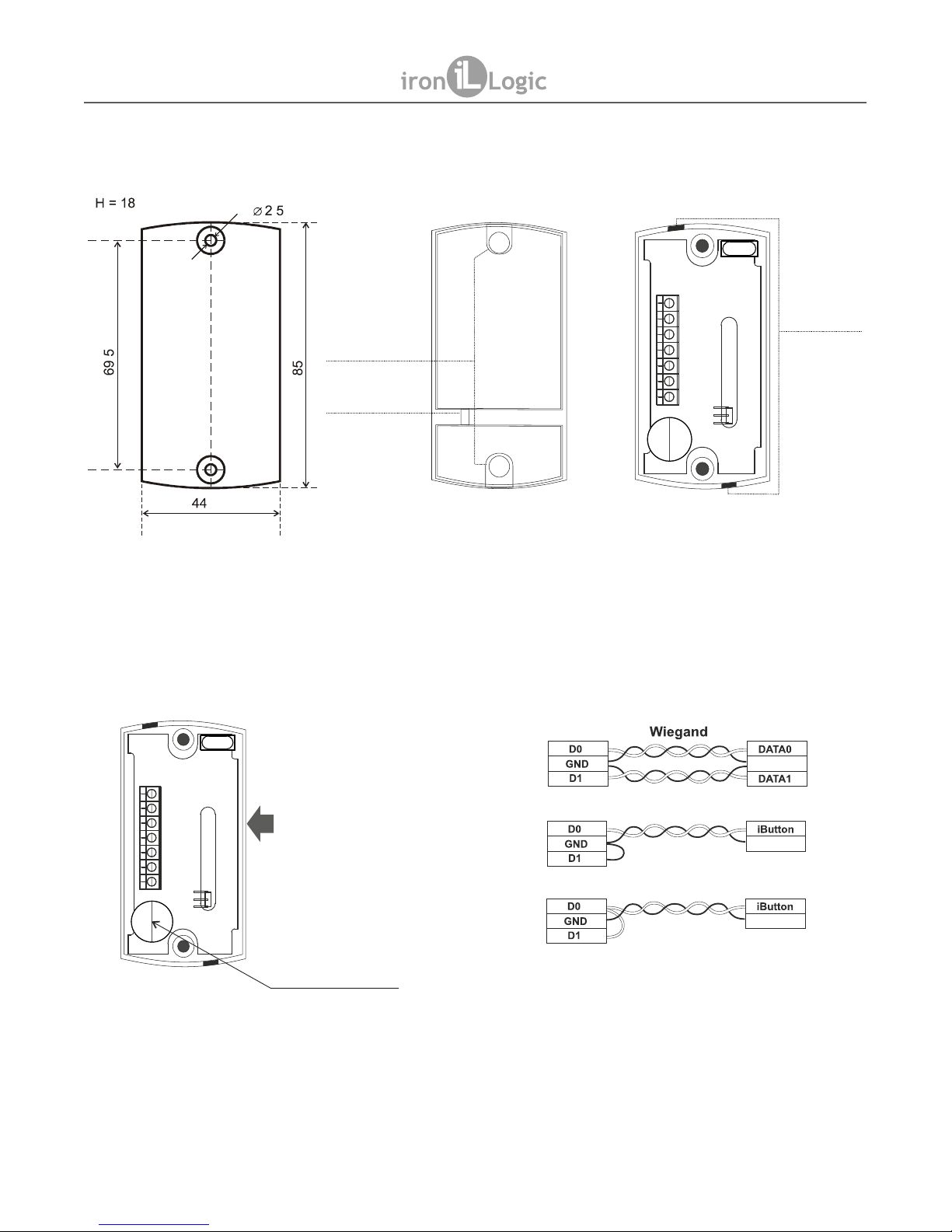
2. MOUNTING AND CONNECTION
The reader should be mounted on a flat surface, in a place allowing unimpeded proximity card
access to the reader.
To mount the reader, perform the following operations:
1. Mark and drill the mounting holes of the same size as the reader case holes (Fig. 1)
2. Connect wires to the reader socket, according to layouts on Fig. 4 and Fig. 5.
3. Break out a thin tab in the case from the side where the cable must come out (Fig. 3),
and feed the cable through. When the power is connected to the reader, the red LED will
come up.
4. Mount the reader in the desired place and fix it with screws.
5. Close the reader case openings with plugs (Fig. 2).
Note 1: Do not install readers closer than 10 cm one from another.
Note 2: To avoid electrical interference when connecting the reader to the controller, a UTP
cable is recommended, such as CAT5e UTP cable (see Fig. 5).
3. OPERATION
Reader operation without external indication control:
1. When power is supplied, in standby mode (no card in working zone), the LED shines red.
2. On card approach, its number is acquired. If done successfully, the LED turns green for a
short time, then switches off, at the same time a short beep also sounds.
3. While the card remains within the reader working zone, the LED stays off.
External indication control for red/green colours of the LEDs and the buzzer is done by shorting
the corresponding terminal (LED R, LED G, BEEP) to the common ground terminal (GND).
External indication control can be used in parallel with internal indication control; by default, the
LED and the buzzer are internally controlled. After external indication control signal has been
activated for one of indication modes (for example, for the LED), that mode becomes externally
controlled, while the other (in this example, the buzzer) remains under internal control.
Page 1
Matrix II MF-I
Mifare 13.56MHz RFID reader
with connection via iButton / Wiegand-26 protocols
User Manual
MATRIX II MF-I
www.ironlogic.me
Page 2
Page 2
Fig. 1
BEEP
DATA 1
+12V
LED R
LED G
DATA 0
GND
Fig. 3
Fig. 2
Fig. 4
BEEP
DATA 1
+12V
LED R
LED G
DATA 0
GND
MATRIX II MF-I
www.ironlogic.me
Holes
to feed
the cable
through
mm
mm
mm
mm
mm
LED
Plugs
Socket terminals:
1. Power supply +12 V
2. Common ground (-)
3. DATA0 output
4. DATA1 output
5. LED-G (external control for green LED)
6. LED-R (external control for red LED)
7. BEEP (external control for the buzzer)
To increase buzzer volume,
remove this sticker
Reader
ACS Controller
iButton (DS1990A emulation)
iButton (One-time transmission)
Common
Common
Common
Fig. 5
Connecting the reader to ACS controller.
CONNECTION LAYOUT
Page 3

4. PROTECTED MODE
In the Protected Mode, the reader reliably protects the ACS from unauthorised access. To
initialise the Protected Mode, an IronLogic Object card containing a special key is required. This
key is stored onto blank access cards using a Z-2 USB MF desktop reader with specific custom
firmware. To store the special key to a Matrix II MF-I reader, touch it with an IronLogic Object
card. Once this is done, the Matrix II MF-I will transmit to the controller only UIDs (serial
numbers) of initialised cards. This reader supports simultaneous holding of up to 10 IronLogic
Object cards.
The first IronLogic Object card stored into Matrix II MF-I becomes the Master card. That card
allows storing other IronLogic Object cards and switching off the Protected Mode. Without this
Master card, the reader cannot be reverted to Unprotected (Initial) mode.
4.1 Switching Between Protected and Unprotected Mode
From the factory, the reader arrives in Unprotected mode, transmitting to the controller the UIDs
of all cards it could read.
4.1.1 Entering Protected Mode
1) On an unpowered reader, connect DATA0 and LED R terminals.
2) Power on the reader.
3) If the LED is blinking red and asignal is sounding, the reader is already in Protected Mode.
4) If the LED is shining solid red, touch the reader with the IronLogic Object card. The reader
changes LED colour to green and issues a beep for 1 second. The Object card has now been
stored into reader as a Master card.
5) Power off the reader.
4.1.2 Storing Object Cards (Up to 10)
1) Ensure that the reader is powered on and operational.
2) Touch it with the Master card; the LED starts blinking red. Keep touching the reader with
additional Object Cards, leaving no more than 16 s in between the cards. Each new card is
acknowledged with a green LED flash.
3) To leave Storing Object Cards mode, either wait 16 s, or touch the reader again with the
Master card.
4.1.3 Leaving Protected Mode
1) On an unpowered reader, connect DATA1 and LED R terminals.
2) Power on the reader.
3) If the LED is blinking red and a signal is sounding, the reader is already in Unprotected
mode.
4) If the LED is shining solid red, touch the reader with the Master IronLogic Object card. The
reader changes LED colour to green and issues a beep for 1 second. All the Object cards
stored into the reader will be erased, and Unprotected mode will be activated.
5) Power off the reader.
Page 3
MATRIX II MF-I
www.ironlogic.me
Page 4

5. CONFIGURATION
Regardless of the current Protected Mode activation state, the controller interface parameters
can be configured. Initially, Wiegand transmission protocol is active. To select iButton protocol,
connect DATA1 terminal to GND terminal. iButton (Dallas Touch Memory) is transmitted via
DATA0.
5.1 Parameter Numbers and Values
Note: (*) Factory default.
5.2 Manual Parameter Setup
1) On an unpowered reader, connect BEEP and DATA0 terminals, then LED R to GND
terminals.
2) Power on the reader.
3) Choosing parameter: the reader LED starts to beep in sequences, synchronously flashing
LED red. The flashes/beeps count in a sequence (1…3) corresponds to active parameter
number.
4) When the desired parameter number is active, connect LED G and GND terminals. The
reader will confirm the parameter choice, and will switch into indicating parameter value.
5) Indicating parameter value is similar to indicating parameter number, but instead of LED
flashing red, it's flashing green. Parameter values start with the current parameter value.
6) To confirm the currently active parameter value: connect LED G and GND terminals. The
new value is stored.
7) Power off the reader.
8) To adjust another parameter, power it on again.
Page 4
MATRIX II MF-I
www.ironlogic.me
Parameter Value Description
1. Wiegand bit
width
1 * Wiegand 26 (3 bytes)
2 Wiegand 34 (4 bytes)
3 Wiegand 42 (5 bytes)
4 Wiegand 50 (6 bytes)
2. iButton
transmission
bit width
1 * iButton transmits ALL UID bytes (up to 6,
depending on the card UID).
2 iButton transmits ONLY the number of bytes
defined by Parameter 1
3. 7-byte UIDs
encoding
1 * As in CP-Z 2MF reader
2 As in Matrix III Net reader
3 As in CP-Z 2MF reader, but with shift and
removal of first digit 0x04
Page 5

5.3. Configuration via RS-485 Link
Configuration via an RS-485 link requires Reader Config software (see www.ironlogic.me
website) and Z-397 Guard converter.
1) Connect the reader to an RS-485 connector:
a. DATA0 to A;
b. DATA1 to B;
c. GND to G.
2) Connect BEEP and DATA0 terminals.Power on the reader.
3) Disconnect BEEP from DATA0. RS-485 link on the reader is now active until power off.
4) Launch the Reader Config software, choose the converter COM port, then configure the
parameters.
6. SPECIFICATIONS
- Working frequency: .................................................................13.56 MHz;
- Supported tokens type: ..................................Mifare Ultralight, Mifare ID,
Mifare Standard (Classic) 1K and 4K;
- Card/key fobs reading distance: .................................................2…6 cm;
- Output protocol: ......................iButton (Dallas Touch Memory), Wiegand;
- Line distance from controller:
via iButton protocol: ................................................................up to 15 m;
via Wiegand protocol: ...........................................................up to 100 m;
- Card reading status indication: ....visual bicoloured LED, audial buzzer;
- Indication control: .........................................................internal / external;
- Power supply voltage: ................................................................12 V DC;
- Current in Card Standby mode: ............................................up to 40 mA;
- Dimensions: ...................................................................85 x 44 x 18 mm.
7. OPERATING CONDITIONS
Ambient temperature: -30…40°C.
Humidity: ≤ 98% at 25°C.
When operating under non-recommended conditions, device parameters can deviate from
specified values.
8. PACKAGE CONTENTS
- Matrix II MF-I RFID Reader: ...1
- Plugs: ....................................2
- Screws 3*30: ..........................2
- Wall plugs: .............................2
Page 5
MATRIX II MF-I
www.ironlogic.me
Page 6

9. LIMITED WARRANTY.
This Device is covered by limited warranty for 24 months.
The warranty becomes void, if:
- this Manual's guidelines are not followed;
- the device has suffered physical damage;
- the device has visible traces of exposure to moist and/or aggressive chemicals;
- the device circuits have visible traces of tampering by unauthorised parties.
Under this warranty, the Manufacturer shall repair the device or replace any broken parts as
required, free of charge, in cases where the fault is caused by a Manufacturer's defect.
10. IRONLOGIC CONTACTS
Headquarters:
RF Enabled ID Limited
34 Ely Place, London, EC1N 6TD, UK
E-mail: marketing@rfenabled.com
Development and production:
AVS LLC
7, Bobruiskaya street, Saint-Petersburg, 195009, Russian Federation
E-mail: marketing@rfenabled.com
Phone: +78122411853; +78125421185
www.ironlogic.ru
Authorized representative in the European Union:
SIA IRONLOGIC
79A, Slokas iela, LV-1007, Riga, Latvia
E-mail: info@ironlogic.lv, headstaff@ironlogic.lv
Phone: +37166181894; +37124422922
www.ironlogic.me
Page 6
MATRIX II MF-I
www.ironlogic.me
The symbol of crossed-throught waste bin on wheels means that the product
must be disposed of at f separate collection point. This also applies to the product
and all accessories marked with this symbol. Products labeled as such must not
be disposed of with normal household waste, but should be taken to a collection
point for recycling electrical and electronic equipment. Recycling helps to reduce
the consumption of raw materials, thus protecting the environment.
 Loading...