

Page 1

Matrix III EH
EM-Marine / HID ProxCard II 125KHz RFID reader
with connection via iButton (1-Wire) / Wiegand-26 protocols
User Manual
1. GENERAL INFORMATION
Matrix III EH Reader is used in Access Control Systems (ACS). The reader transmits into the
controller the codes of EM-Marine or HID ProxCard II tokens (cards or key fobs) presented to it, via
iButton (Dallas Touch Memory) or Wiegand-26 protocols.
2. OPERATION
The reader operation without activating external indication control (i.e. staying under internal
indication control):
1. In standby mode, the red LED shines solid.
2. On card approach, the red LED goes off and the green LED flashes once, and a short beep
sounds.
3. While the card remains within working zone, no LED indication is provided.
The external indication control for the LEDs and the buzzer is initiated by connecting corresponding
terminals to common ground. The external indication control for one mode can be used with internal
indication control for another; if, for instance, external indication signal for LEDs is activated, the
LEDs get under external control, while the buzzer remains under internal control.
3. MOUNTING AND CONNECTION
To mount the reader, perform the following sequence:
- Mark and drill the mounting holes per Fig. 2;
- Connect the reader wires according to Table 1;
- Insulate all wire junction points;
- Power up the device (the red LED will come on);
- Test the reader operation by touching it with a token;
- Mount the reader in its desired place and fix it with screws;
- Install the decorative cover and fix it with a screw.
Note 1: Leave 10 cm or more between any two readers.
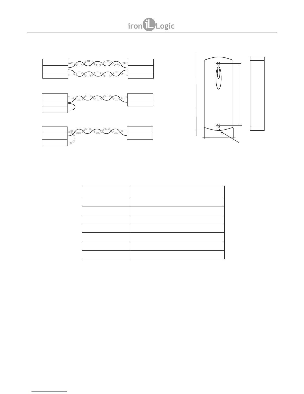
Note 2: To achieve the specified distance from controller, a UTP cable (e.g. CAT5e compatible)
must be used as follows:
- When using iButton protocol, one wire from the twisted-pair should be connected to GND and
another to DATA0 terminal.
- When using Wiegand 26 protocol, the first twisted pair is connected between GND and DATA0,
and the second one between GND and DATA1, as per Fig. 1.
page 1
MATRIX III EH
www.ironlogic.me
Page 2
4. SPECIFICATIONS
- Working frequency: ...................................................................125 kHz;
- Used token types: ......................................EM-Marine, HID ProxCard II;
- Reading distance: ...................................................................2…10 cm;
- Output interface: ..............Wiegand-26, iButton (Dallas Touch Memory);
- Line distance via iButton protocol: .........................................up to 15 m;
- Line distance via Wiegand-26 protocol: ..............................up to 100 m;
- Power supply voltage: ...............................................................12 V DC;
- Power supply current: .........................................................max. 35 mA;
- Status indication: .........................................visual LED, audial buzzer;
- External status indication control: ..........for audial and visual indication;
- Case material: ......................................................................ABS plastic;
- Dimensions: ..............................................................120 × 45 × 22 mm.
Figure 1. Choosing the transmission protocol.
Figure 2. Device Dimensions.
DATA1
GND
D0
DATA0
D1
GND
D0
iButton
D1
GND
D0
iButton
D1
IButton (One-time transmission)
Wiegand
IButton (DS1990A emulation)
ACS controller
Reader
GND
GND
GND
screw
120 mm
82 mm
45 mm
Wire Colour Wire Designation
Red +12V
Black Common (-)
White DATA0
Brown DATA1
Green External control for the green LED
Yellow External control for the red LED
Blue External control for the buzzer
Table 1. Controller connections.
MATRIX III EH
www.ironlogic.me
page 2
22 mm
Page 3

5. OPERATING CONDITIONS
Ambient temperature: -30…40°C.
Humidity: ≤ 98% at 25°C.
When operating under non-recommended conditions, device parameters can deviate from
specified values.
6. PACKAGE CONTENTS
- MATRIX III EH Reader: ...1
- Screw: .............................1
- Screws 3.5×40: ...............2
- Wall Plugs: ......................2
7. LIMITED WARRANTY.
This Device is covered by limited warranty for 24 months.
The warranty becomes void, if:
- this Manual's guidelines are not followed;
- the device has suffered physical damage;
- the device has visible traces of exposure to moist and/or aggressive chemicals;
- the device circuits have visible traces of tampering by unauthorised parties.
Under this warranty, the Manufacturer shall repair the device or replace any broken parts as
required, free of charge, in cases where the fault is caused by a Manufacturer's defect.
MATRIX III EH
www.ironlogic.me
page 3
Page 4

8. IRONLOGIC CONTACTS
Headquarters:
RF Enabled ID Limited
34 Ely Place, London, EC1N 6TD, UK
E-mail: marketing@rfenabled.com
Development and production:
AVS LLC
7, Bobruiskaya street, Saint-Petersburg, 195009, Russian Federation
E-mail: marketing@rfenabled.com
Phone: +78122411853; +78125421185
www.ironlogic.ru
Authorized representative in the European Union:
SIA IRONLOGIC
79A, Slokas iela, LV-1007, Riga, Latvia
E-mail: info@ironlogic.lv, headstaff@ironlogic.lv
Phone: +37166181894; +37124422922
www.ironlogic.me
The symbol of crossed-throught waste bin on wheels means that the product
must be disposed of at f separate collection point. This also applies to the product
and all accessories marked with this symbol. Products labeled as such must not
be disposed of with normal household waste, but should be taken to a collection
point for recycling electrical and electronic equipment. Recycling helps to reduce
the consumption of raw materials, thus protecting the environment.
MATRIX III EH
www.ironlogic.me
page 4
 Loading...