

Ironclad HIL885 Assembly Instructions And Owner's Manual

1
ADJUSTABLE BASKETBALL SYSTEM
MODEL: HIL885
ASSEMBLY INSTRUCTIONS AND OWNER'S MANUAL
!
!
WARNING
IRONCLAD SPORTS, INC
902 Corey Road, Hutchinson, KS 67501
Telephone: 620-662-2233
www.ironcladsports.com
IRONCLAD SPORTS , INC
HIGHLIGHT HOOPS
Keep this instruction manual in case you have to contact the manufacturer for replacement parts.
FAILURE TO COMPLY WITH ANY OF
THE WARNINGS IN THESE INSTRUCTIONS
MAY RESULT IN SERIOUS PERSONAL
INJURY.
FAILURE TO COMPLY MAY ALSO
RESULT IN PROPERTY DAMAGE.
PLEASE HEED ALL WARNINGS AND
CAUTIONS TO ENSURE YOUR SAFETY.
DO NOT ATTEMPT TO ASSEMBLE
THIS SYSTEM WITHOUT CAREFULLY
READING AND FOLLOWING ALL
INSTRUCTIONS. BEGIN BY IDENTIFYING
AND TAKING INVENTORY OF ALL PARTS
USING THE PARTS LIST PROVIDED.

TOOLS AND MATERIALS REQUIRED FOR ASSEMBLY
(Not Included)
1. 2 Adjustable Wrenches 10. Concrete-1/2 yard or 14-16
2. Socket Set Bags, (80 lb. bags)
3. 9/16" Wrench 11. Phillips Head Screwdriver
4. 3/4" Wrench
5. 15/16" Wrench 13. Carpenter's Level
6. ½" Wrench 14. Water Supply
7. Hammer or Mallet
8. Tape Measure
9. Shovel
**A MINIMUM OF SIX ADULTS IS
REQUIRED TO LIFT UNIT INTO PLACE**
STOP! STOP!
BEFORE YOU START
A. Identify and inventory all parts using the checklist boxes in the parts list. Be sure to
keep the hardware bags and their contents separate. If any parts are missing call
our Customer Service Department ( ).620-662-2233
B. Test fit all Bolts by inserting them into the respective hole. If necessary, carefully
scrape away any excess powder coating buildup from inside the holes. Do not
scrape away all of the powder coating. Bare metal may rust.
!
!
SAFETY INSTRUCTIONS
FAILURE TO FOLLOW THESE SAFETY INSTRUCTIONS MAY RESULT IN SERIOUS INJURY OR PROPERTY DAMAGE
AND WILL VOID THE WARRANTY. The owner must ensure that all players know and follow these rules to safely operate the
system. Proper and complete assembly, use and supervision is essential for proper operation and to reduce the risk
of accident or injury. A high probability of serious injury exists if this system is not installed, maintained, or operated
properly.
● ●
If using a ladder during assembly, use extreme caution. Follow all warnings and cautions on the ladder carefully. 6
people are required to lift the unit into place. Before digging, contact the appropriate agency to locate underground
●
power cables, gas, and water lines. Do not install the system within 20 feet of overhead power lines. Climate, corrosion,
●
or misuse could result in system failure. If technical assistance is required, contact the manufacturer. Minimum
● ●
operational height is 7'6 to the Rim. Most injuries are caused by misuse and /or failure to follow instructions.”
Use caution when using the system.
2
12. A minimum of 2 Ladders
Verify all parts listed on packing list are present prior to installation. Contact our Customer
Service at 620-662-2233 for assistance with replacement of any parts missing or damaged.
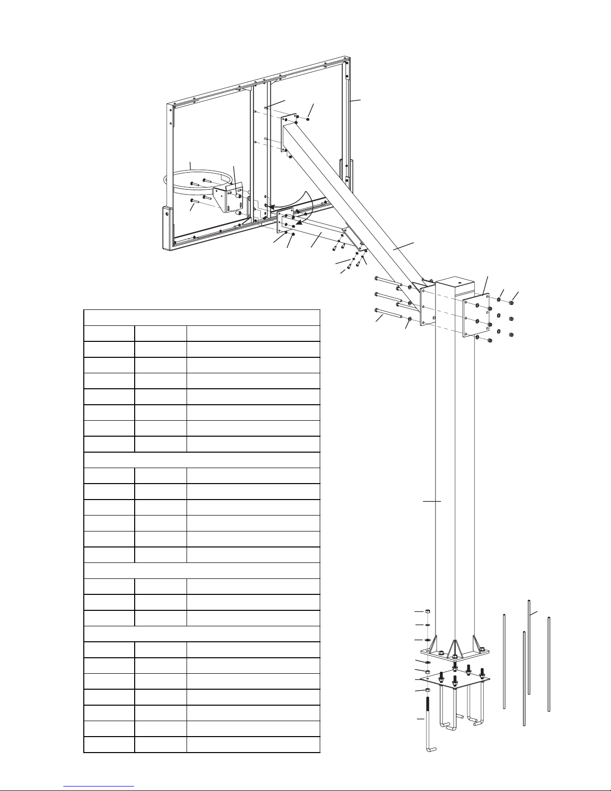
3
ITEM QTY DESCRIPTION
A 1 8"x8"Main Post
B 1 Main Extension Arm
C 1 Small Extens ion Arm
D 1 Extension Arm Plate
E 1 Backboard with frame
F1Rim
G 1 Rim spacer (plas tic & steel)
U1 1 Anchor Template
U2 6 18mm Anchor J-bolts
U3 12 Thick washer for J-bolts
U4 18 Hex nut M18
U5 4 Anchor Rebar 36"L
U6 6 Lock Washer M18
R1 4 Carriage bolt M10x70
R2 4 Flat Washer M10
R3 4 Flange nut M10
ITEM QTY DESCRIPTION
1 6 Hex bolt M16x250mm
2 12 Flat Washer M16s
3 6 Lock nut M16
4 4 Hex Bolt M10x30mm
5 4 Lock washer M10
6 4 Flat washer M10
HARDW ARE LIST
PARTS LIST
RIM HARDWARE
UNDERGROUND PARTS
U4
U6
U3
U3
U4
U1
U4
U2
U5
A
B
C
D
E
F
G
R1
R2
R3
Pre-installed
bolts &nuts on
backboard fra me
Pre-installed
bolts &nuts on
backboard fra me
1
2
2
3
4
5
6
 Loading...