

Page 1
TOOLS NEEDED
Stud Finder (Optional 1/4" Nut Driver (Optional)
Non-Swivel Models
Recessed Installation / four - #10 x 1 1/2" wood screws
Surface Mounting / two - #14 x 4" wood screws
Swivel Models
Recessed Installation / two - #10 x 1 1/2" wood screws for
Surface Mounting / two - #14 x 4" wood screws
INSTALLATION INSTRUCTIONS
Assemble the required tools and parts before starting the installation. Read and
follow the instructions provided using the tools listed.
Carpenter's Level 1/8" Drill Bit
Tape Measure Safety Glasses
Utility Knife Small Flat Head Screwdriver
Drill (Electric Recommended)
1/4" drill bit (Surface Mount)
PARTS SUPPLIED
E-46,NE-46, E-42,
NE-42, IAW-42 (IAW-42 only / two - #14 x 2 1/2" wood screws)
AE-46, AE-42, ANE-46, top portion of cabinet
ANE-42, UD-42 two - #14 x 2 1/2" P h illips screws for t op side brackets
Look for the small plastic bag attached to the bottom bar of the
ironing board. This bag contains the supplied parts.
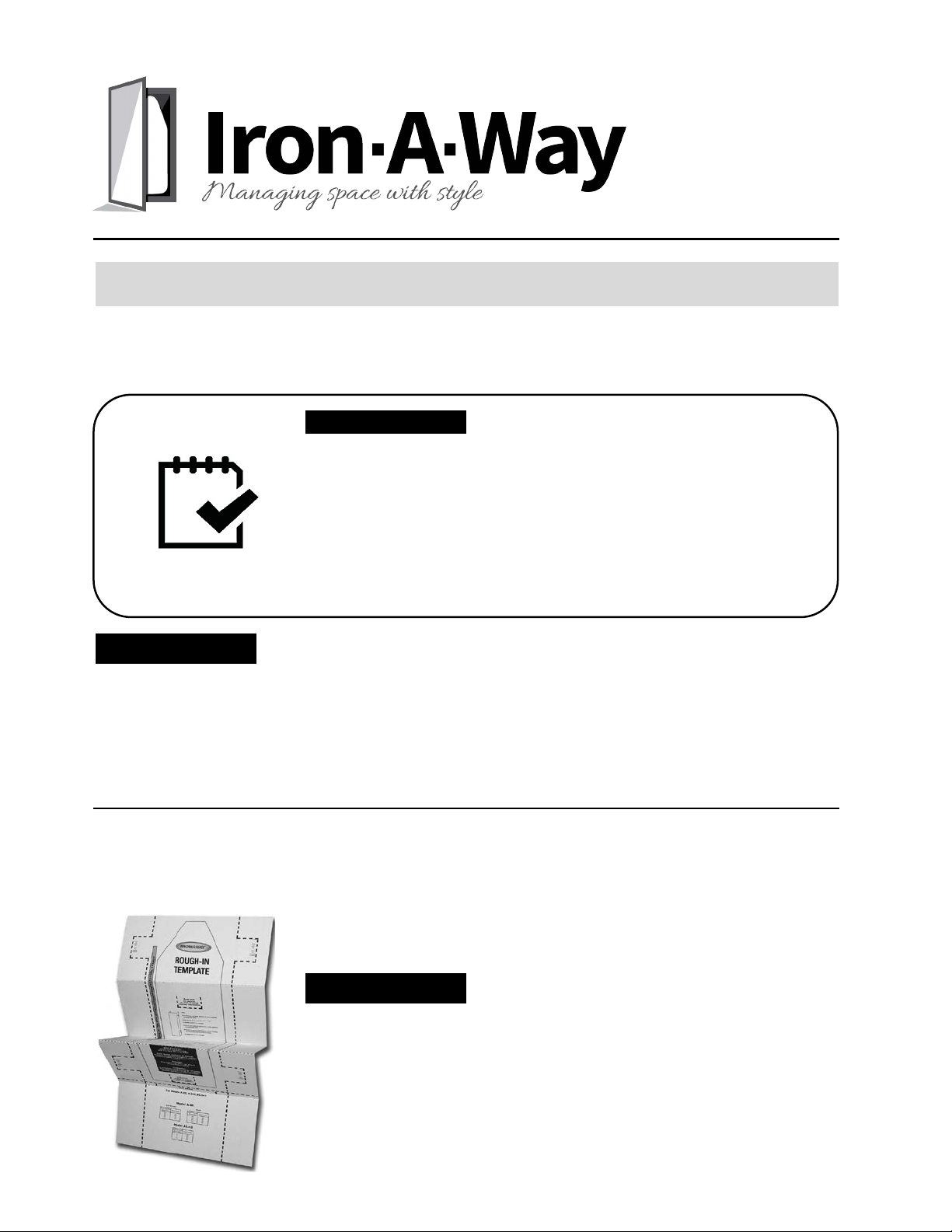
ROUGH-IN KIT
Rough-In Kit available for use prior to drywall being installed. Great
for new construction or open wall reconstruction when remodeling.
Rough-In Kit simplifies installation at a later date when room
completed and wall coverings and trim have been applied.
Page 2
RECESSED MOUNTING
You must verify the default position of the ironing board before installing the ironing center. Refer to the Ironing Board
Height Chart below for the proper height of the various installation configurations. Make sure you use the correct model
when selecting your board height.
E-46 E-42
Ironing Ironing Ironing Ironing
Board Height Board Height Board Height Board Height
Opening Height Regular Adjusted Regular Regular Adjusted Regular Regular Adjusted Regular
Above Floor Position Position Position Position Position Position Position Position Position
29" 36" 40" 36" 36"
28" 35" 39" 35" 35"
27" 34" 38" 34" 34"
26" 33" 37" 33" 33"
25" 36" 40" 36"
24" 35" 39" 35"
23" 34" 38" 34"
22" 33" 37" 33"
21"
20"
16" 32" 36"
15" 31" 35"
14"
30"
34"
13" 29" 33"
Note: The user can adjust height of board after installation of "A" & "U" models with a 4" differential from regular height to a maximum adjusted position.
1. Using a stud finder, locate the wall studs to be used for mounting.
2. Locate the existing wiring or other utilities in the wall to prevent drilling into or severing a wire or other utility during installation.
3. Determine the desired location has adequate clearance for ironing. Door opens approximately 180°. Allow at least 16" from side of
cabinet for door to swing open.
Distance from Wall to Tip of Ironing Board 50 7/8" 46 1/4" 46 7/8" 42" 46 5/8" 40 1/4"
Swivel Clearance from Cutout Opening 16 7/8" N/A 14 5/8" N/A 14 7/8" N/A
Distance from Wall in Full Swivel Position 32 1/2" N/A 32 7/8" N/A 33" N/A
Standing Area Clearance * 24" 24" 24" 24" 24" 24"
4. Cut an opening in the wall per the opening sizes shown below.
AE-46, ANE-46, E-46, & NE-46 14 3/8" x 59 7/8" x 3 7/8"
UD-42 14 3/8" x 59 7/8" x 3 7/8"
AE-42, ANE-42, E-42, & NE-42 14 3/8" x 51 1/4" x 3 7/8"
IAW-42 14 1/2" x 51 x 3 7/8"
5. Attach 2" x 4" cross support cleat between the studs, level with the bottom of the opening.
6. The cabinet will be attached to studs using four screws, one in each side at the top of cabinet and one in each side at bottom
of cabinet. Using a 1/8" drill bit, pre-drill pilot holes approximately 14" from the top of the cabinet and 2 1/2" from the back of the
cabinet. Models without a swivel, pre-drill pilot hole approximately 14" from the bottom and 2 1/2" from the back of the cabinet.
Models with swivel board, complete Steps 8, 9, and 10 before pre-drilling pilot holes for bottom location.
Note: If an electrical model is being installed, the temporary removal of the electrical wireway may be helpful to complete this step.
Reinstall electrical wireway after cabinet is attached to studs.
7.
If installing an electrical model, please review Electrical Instructions now. If installing a non-electrical model, do not install your own
electrical outlet inside cabinet. Warranty voided if independent electrical outlet installed within non-electrical ironing center cabinet.
8. Begin installation by carefully lifting ironing center into the wall opening.
9. Plumb and level the cabinet. Shim to fit.
10. For models with swivels, continue with Step 11. For models without swivels, attach cabinet to studs using the four pre-drilled holes
with four #10 x 1 1/2" screws. Once complete, continue to Step 12.
11. Attach cabinet to studs using the two pre-drilled holes and two #10 x 1 1/2" screws for the top installation. Locate the side ironing
board brackets that are secured to the cabinet with three screws each. Remove the top screw only from each side bracket. Use
this location to pre-drill pilot holes for bottom installation location. Pre-drill a pilot hole through top hole in each bracket into stud
Finish attaching cabinet into studs using the #14 x 2 1/2" screws for the just completed two pre-drilled holes in each side bracket.
12. Decorative trim may be added to cover any irregularity on wall.
AE-46
ANE-46
AE-42
ANE-42
Ironing
Board Height
UD-42
Model
Ironing
Board Height
NE-46 NE-42 IAW-42
AE-46 E-46 AE-42 E-42
ANE-46 NE-46 ANE-42 NE-42 UD-42 IAW-42
* The suggested distance from the side of the ironing board where the user typically stands to ensure adequate space for ironing.
Opening Size
Page 3

SURFACE MOUNTING
You must verify the default position of the ironi ng board before installing the ironing center. Refer to the Ironing Board
Height Chart below for the proper hei ght of the various installation configurations. Make sure you use the correct model
when selecting your board hei ght. It is recommended a surface mount kit be installed when surface mounting
recessed units.
E-46 E-42
Ironing Ironing Ironing Ironing
Board Height Board Height Board Height Board Height
Regular Adjusted Regular Regular Adjusted Regular Regular Adjusted Regular
Position Position Position Position Position Position Position Position Position
29" 36" 40" 36" 36"
28" 35" 39" 35" 35"
27" 34" 38" 34" 34"
26" 33" 37" 33" 33"
25" 36" 40" 36"
24" 35" 39" 35"
23" 34" 38" 34"
22" 33" 37" 33"
21"
20"
16" 32" 36"
15" 31" 35"
14" 30" 34"
13" 29" 33"
Note
1. Using a stud finder, locate the wall stud to be used for mounting. Stud should be located as close to the center of cabinet as possible.
2. Locate the existing wiring or other utilities in the wall to prevent drilling into or severing a wire or other utility during installation.
3. Determine the desired location has adequate cle arance for i roning. Door opens approximately 180°. Allow at least 16" from side of
cabinet for door to swing open.
Distance from Wall to Tip of Ironing Board 50 1/4" 46 7/8" 50 1/4" 46 7/8" 50 1/4" 43 1/4"
Swivel Cl earance from Cutout Opening 16 7/8" 14 5/8" 16 7/8" 14 5/8" 16 7/8" N/A
Distance from Wall in Full Swivel Position 32 1/4" 32 5/8" 32 1/4" 32 5/8" 32 1/4" N/A
Standing Area Clearance * 24" 24" 24" 24" 24" 24"
4. Using a 3/16" drill bi t, pre-drill a pilot hol e into the wall stud where the cabinet will be attached to the wall taki ng care that the
installation height is as desired.
5. Determine the proper mounting screw location inside cabinet so mounting position is located on wall stud as intended. Location for
mounting screw should be as close to the center of the cabinet as possibl e .
6. Using a 1/4" drill bit, pre-drill hole in the upper and lower cross braces located inside the cabinet as determined in the previous step
taking care that the holes in both braces are drilled to same measurement.
7. Partially start mounting #14 x 4" screw into upper cross brace for installati on of ironing center.
8. If installing an electrical model, review Electrical Instructions now (back page.) If installing a non-electrical model, do not install your
own electrical outl e t i nside cabinet. Warranty voided if independent electrical outlet installed within non-electrical ironing cabinet.
9. Begin installation by carefully lifting the ironing center into position.
10. Attach cabinet to wall by fully inserting the screw in the upper cross brace into the pre-drilled hol e in the wall stud.
11. Plumb and level the cabinet. Shim if necessary. Tighten cabinet to wall by fully turning instal lation screw.
12. Insert second #14 x 4" screw into pre-drilled hole in bottom brace of cabinet and attach to wall making sure cabinet remains
level and square.
13. Decorative trim may be added to cover any irregularity on wall.
Additonal Recommendation: On all adjustable swivel models, l ocate si de ironing board brackets that are secured to the cabinet with
three screws each. Remove the top screw only from each side bracket. Use this location to pre-drill pilot holes into trim. Insert into the
two pre-drille d holes in each side bracket #14 x 1" screws (not include d.)
Board Height
Board Height
UD-42
AE-46
AE-42
ANE-46
ANE-42
Ironing
Ironing
Opening Height
Above Floor
NE-46 NE-42 IAW-42
: The user can adjust height of board after installation of "A" & "U" models wit h a 4" differential from regular height to a maximum adjusted position.
AE-46 E-46 AE-42 E-42
ANE-46 NE-46 ANE-42 NE-42 UD-42 IAW-42
* The suggested distance from the side of the ironing board where the user typically stands to ensure adequate space for ironing.
Page 4

WARNING: TURN OFF POWER AT SERVICE ENTRANCE BEFORE INSTALLING, WIRING OR SERVICING
NOTE: Opening in the top of the ironing center cabine t
electrical supply wire is located 2 1/4" on center from left side
for the of cabinet and 2 1/4" on center from the back of the
cabinet on all el ectrical models excepts UD-42. The UD-42
supply wire is located 2 1/4" on center from the right side of
cabinet and 2 1/4" on center from the back of the cabinet.
NOTE: In the front cover of the electrical wireway, near the top, there is a loose black and a loose white wire
Verify that there is ample supply wire available to run from the top of the ironing center cabinet to the approximate
220 West Jackson
Morton, IL 61550-1551
Bus: (309) 266-7232
Fax: (309) 266-5088
www.ironaway.com
ELECTRICAL INSTRUCTIONS
THIS PRODUCT.
All electrical work must be done in accordance with all applicable electrical codes.
SUPPLY LINE: 110 Volt / 15 Amps
1. Open the front cover by removing the screw at the top and bottom of the electrical wireway.
pigtail that are provided for hookup to the electrical supply line.
2. Locate and remove the knockout at the top of the back cover of the electrical wireway and install a 3/8" romex
connector where the knockout was removed.
3.
location of the electrical pi gtai ls. (A free wire length of approximately 48" is recommended.)
4. Begin to place the ironing center into its location while feeding the free suppl y wire through the opening in the
top of the ironing center cabinet and the 3/8" romex connector attached to the back cover of the electrical
wirew a y. (If surface mounting, a vent hole wil l need to come through the back of the cabinet for electrical
feed of wire. Approximate center diameter position of electrical knockout is 24 1/2" down from top left of
cabinet and 2 13/16" from left side of cabinet.
5. Put into place and secure the ironing center cabinet as identified i n Step 8 through 13 of the Recessed Mounting
or Step 9 through 13 of Surface Mounting whichever mounting method is appli cable.
6. Connect all power supply wires and ground wires i n accordance with all electrical codes. Trim as necessary
excess supply wire.
7. Place into position the top cover of the electrical wi reway making sure no w ires are pinched when reinstalling
the top cover to the back cover. Reinstall the top screw and bottom screw removed in Step 1 into the
electrical wire cover.
8. Turn on power at Service Entrance to test and verify that electrical components (timer, automatic disconnect
switch, electrical outlet) are working properly.
001072 05/17
 Loading...