

Page 1

Installation
Manual
MODEL: IAW-42
Page 2
PRE-INSTALLATION
TOOLS NEEDED:
- Stud Finder
- 12-14” Level
- 1/4” Nut Driver
(optional)
- Safety Glasses
- Tape Measure
- Utility Knife
- Small Flathead
Screwdriver
- Electric Drill
(with 1/4” & 1/8” drill bit)
SUPPLIED PARTS:
- Two #14 x 4” wood screws
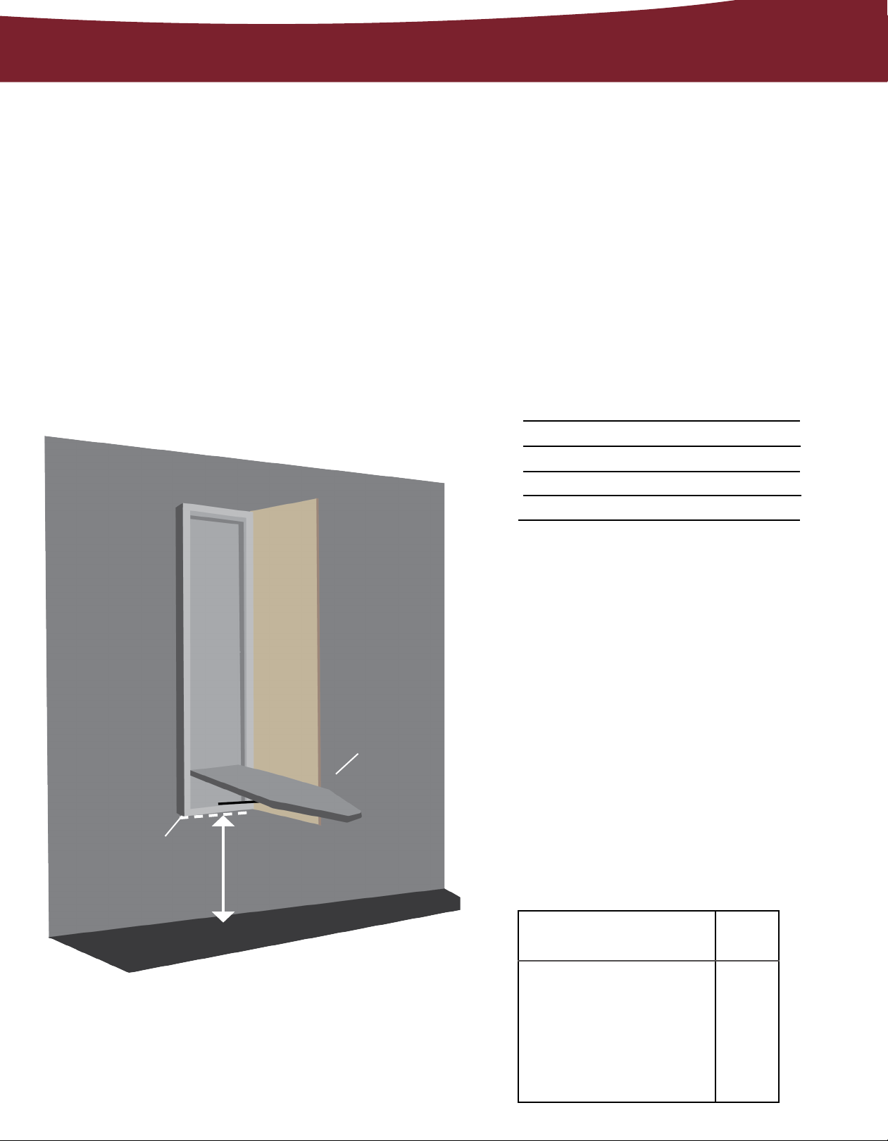
1. DETERMINE MOUNTING HEIGHT
Using the charts provided, determine
the mounting height above oor (the
distance between the oor and the
bottom of the cabinet). First choose
your desired ironing board height
from the left column, then locate the
corresponding mounting height in the
right column.
Desired Ironing
Board Height
36”
35”
34”
33”
Mounting
Height Above
Floor
29”
28”
27”
26”
2. LOCATION OF UNIT
Using a stud nder, locate the wall
studs to be used for mounting, and
mark height of the center of cabinet
on stud where unit will be mounted.
Mounting
Height
Above Floor
Desired Ironing
Board Height
Locate the existing wiring or other
utilities in the wall to prevent drilling
into/severing a wire and/or other utility
during installation.
Make sure your desired mounting
location has adequate clearance for
ironing. The cabinet door opens at 180
degrees; allow 16” from side of cabinet
for door to open. Refer to chart below
for needed space.
Distance from Wall to
Tip of Ironing Board
Standing Area
1/4
40
24”
”
Clearance
The suggested distance from
the side of the ironing where
the user typically stands to
ensure adequate space for
ironing.
Page 3

INSTALLATION
1. PREPARE CABINET
Screws will be drilled through the
upper and lower cross braces inside
the cabinet. Determine location of
screws, ensuring that the location of the
mounting screw is as close to the center
of the cabinet as possible.
2. PRE-DRILL PILOT HOLES
Using a 1/4” drill bit, pre-drill holes in
the upper and lower cross braces
inside the cabinet as determined in
previous step. Ensure that the holes in
both braces are drilled to the same
measurement.
3. LOCATE & MARK STUD
Using a stud nder, locate stud in
wall and mark the wall according
to the pre-drilled holes in cabinet.
Setting cabinet aside, pre-drill holes
in stud using a 1/4” drill bit. Do not
attempt to mount only by hard
board of cabinet.
1
1. UPPER CROSS BRACE
2
2. LOWER CROSS BRACE
Example shown
with studs & unit to
illustrate mounting.
4. PARTIALLY INSERT SCREW
Partially insert a #14 x 4” screw
in the upper cross brace.
5. INSTALL UNIT
Begin installation by carefully lifting
unit into position. Then, attach the
cabinet to the wall by fully inserting
the screw in the upper cross brace
into the wall stud.
Make sure the unit is plumb and
level. Shim if necessary. Fully tighten
installation screw.
 Loading...