

Page 1
Installation
Manual
MODELS:
AE46, AE42, E46, E42, ANE46, ANE42, NE46, NE42
Page 2

TABLE OF CONTENTS
SWIVEL UNITS (AE46, AE42, ANE46, ANE42)............................pg.3
NON-SWIVEL UNITS (E46, E42, NE46, NE42)...........................pg.11
ELECTRICAL INSTRUCTIONS.....................................................pg.17
Premier Storage Systems
220 W. Jackson St, Morton, IL 61550
1-800-536-9495 or info@ironaway.com
Page 3

(BOTTOM OF RACEWAY)
Swivel Units
Models: AE46, AE42, ANE46, ANE42
2
1
4
6
3
ELECTRICAL MODELS
(AE46 SHOWN)
3
NON- ELECTRICAL MODELS
6
(ANE46 SHOWN)
1
GET TO KNOW YOUR UNIT
1. CROSS BRACES
- Three braces for 46” units
- Two braces for 42” units
2. ELECTRICAL RACEWAY
(AE46, AE42)
3. SIDE BRACKETS
4. ELECTRICAL CORD COVER
(AE46 only; AE42
features a cord wrap)
5. ELECTRICAL OUTLET
6. HOT IRON REST
(AE46, ANE46)
Tools Needed:
- Stud Finder
- 12-14” Level
- Tape Measure
- Small Flathead
Screwdriver
- Electric Drill
(with 1/4” & 1/8” drill bit)
- 1/4” Nut Driver
(optional)
- Safety Glasses
- Utility Knife
Supplied Parts:
Recessed Mounting:
- Two #10 x 1 1/2” wood screws for top
portion of cabinet
- Two #14 x 2 1/2” Phillips screws for top
side brackets
Surface Mounting:
- Two #14 x 4” wood screws
3
Page 4

SWIVEL: PRE-INSTALLATION
1. DETERMINE MOUNTING HEIGHT
Using the charts provided, determine
the mounting height above oor (the
distance between the oor and the
bottom of the cabinet). First choose
your desired ironing board height
from the left column, then locate the
corresponding mounting height in the
right column.
AE46 & ANE46
Desired Ironing
Board Height
36”
35”
34”
33”
AE42 & ANE42
Desired Ironing
Board Height
Mounting
Height Above
Floor
29”
28”
27”
26”
Mounting
Height Above
Floor
Desired Ironing
Board Height
36”
35”
34”
33”
25”
24”
23”
22”
2. LOCATE STUDS & UTILITIES
Using a stud nder, locate the wall
studs to be used for mounting.
Locate the existing wiring or other
utilities in the wall to prevent drilling
into/severing a wire and/or other utility
during installation.
Mounting
Height
Above Floor
4 - Swivel Installation
Page 5
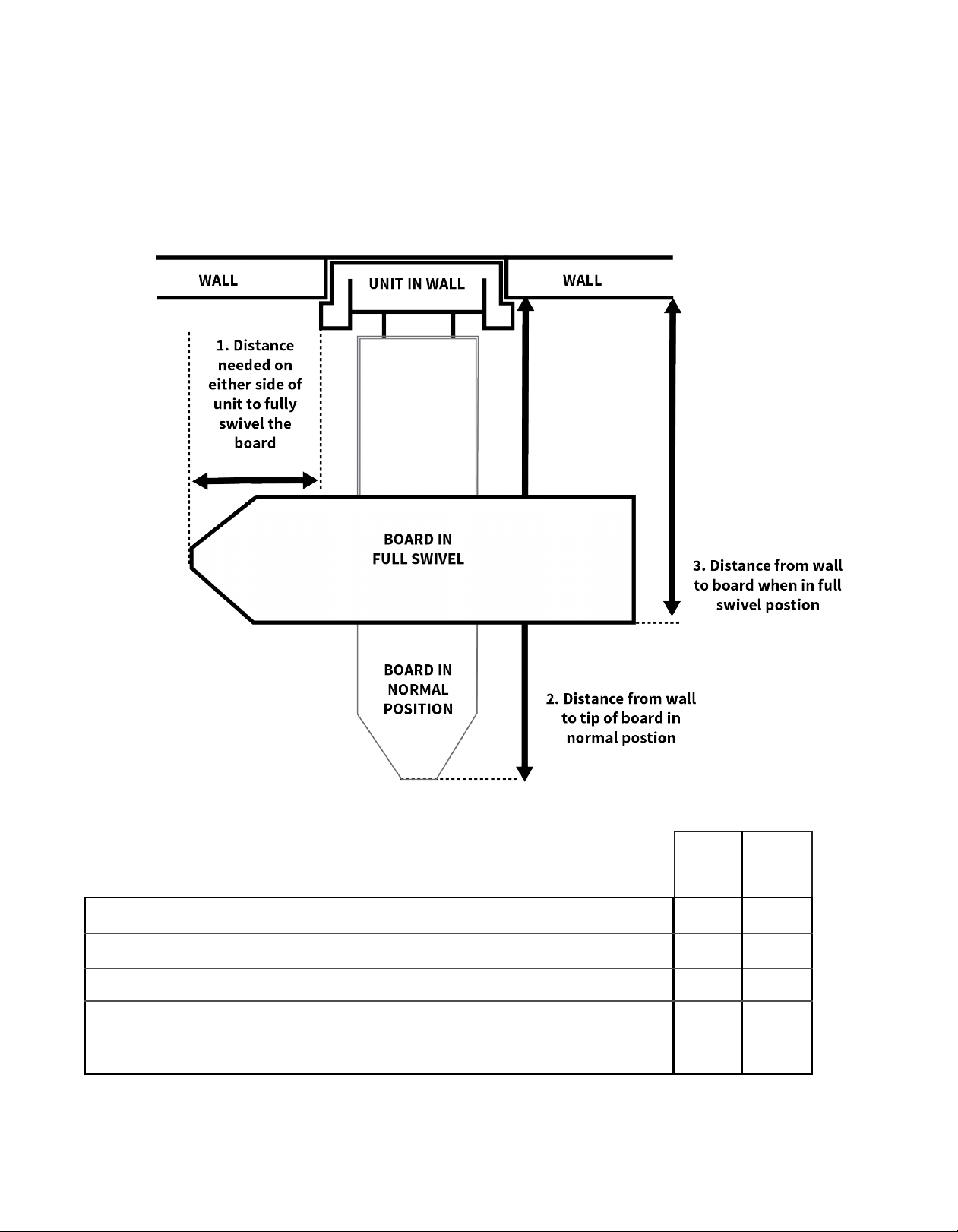
3. ENSURE ADEQUATE SPACE
Refer to the chart provided below to ensure
adequate clearance for ironing. The cabinet
door opens at 180 degrees; allow 16” from side
of cabinet for door to fully open.
1. Distance needed on either side of unit to fully swivel the board
2. Distance from wall to tip of ironing board
3. Distance from wall to board when in full swivel position
4. Standing area clearance (not shown)
The suggested distance from the side of the ironing where the user
typically stands to ensure adequate space for ironing.
AE46
ANE46
7/8
16
7/8
50
7/8
32
” 32
24” 24”
AE42
ANE42
” 14
” 46
5/8
”
7/8
”
7/8
”
Swivel Installation - 5
Page 6

SWIVEL: RECESSED INSTALLATION
Note: Instructions based on installation between 16” on-center studs.
1. CUT WALL OPENING
Cut an opening into the wall based
on unit dimensions given below.
AE46/ANE46: 14
AE42/ANE42: 14
3/8
” x 59
3/8
” x 51
7/8
1/4
” x 3
x 3
7/8
7/8
”
”
2. ATTACH CLEATS
Attach a 2” x 4” cross support
cleat between the studs so it
is level with the bottom of the
opening. This will give support to
the drywall during installation and
the cabinet once installed in the
wall.
3. PRE-DRILL HOLES
Your unit will be attached to the studs by
screws in the upper and lower sides of
the cabinet.
AE46 & AE42: Remove electrical
raceway before proceeding by
removing the top and bottom screws on
the raceway.
Using a 1/8” drill bit, pre-drill holes into
the sides of the cabinet, 14” from the top
and 2
1/2
” from the back.
14” from top of cabinet
CLEAT
1/2
2
” from back
of cabinet
Example shown with exposed
studs & unit to illustrate mounting.
6 - Swivel Installation
AE46 SHOWN
Page 7

MODELS AE46 & AE42:
Refer to electrical instructions on
pg.17 before proceeding to next step.
MODELS ANE46 & ANE42:
Proceed to next step.
DO NOT attempt to install your own
electrical to unit. Warranty is voided if
independent electrical is installed.
4. INSTALL UNIT IN WALL
Begin installation by carefully lifting unit
into the wall opening. Make sure the
cabinet is plumb and level. If needed,
add shims to help unit t snug in place.
5. ATTACH CABINET TO STUDS
Using the pre-drilled holes in top
of cabinet, attach unit to studs
with two #10 x 1
installation.
1/2
” screws for top
6. REMOVE BRACKET SCREW
Locate side ironing board brackets
that are secured to cabinet with
three screws. Then remove the
top screw from each bracket. This
is where the bottom part of your
cabinet will be secured to the
studs.
7. PRE-DRILL HOLES IN SIDES
Pre-drill holes into the cabinet using
the holes in side brackets where
screws were just removed.
Finish installation by screwing the
two #14 x 2
1/2
” screws into the
pre-drilled holes to secure bottom
part of cabinet into the cabinet.
FOR MODELS AE46 & AE42:
Please refer back to electrical
instructions to complete the
electrical part of your installation.
8. INSTALLATION COMPLETE!
Cabinet is now fully installed! If desired,
decorative trim or molding may be
added to cover any irregularities in the
wall.
Example shown with studs
to illustrate mounting.
Swivel Installation - 7
Page 8

SWIVEL: SURFACE MOUNT INSTALLATION
1. PREPARE CABINET
Screws will be drilled through the upper
and lower cross braces (see illustration
on pg.3) inside the cabinet. Determine
location of screws, ensuring that the
location of the mounting screw is as
close to the center of the cabinet as
possible.
2. PRE-DRILL PILOT HOLES
Using a 1/4” drill bit, pre-drill holes in
the upper and lower cross braces
inside the cabinet as determined in
previous step. Ensure that the holes in
both braces are drilled to the same
measurement.
3. LOCATE & MARK STUD
Using a stud nder, locate stud in wall
and mark the wall according to the
pre-drilled holes in cabinet. Setting
cabinet aside, pre-drill holes in wall
using a 1/4” drill bit. Do not attempt
to mount only through hard board of
cabinet.
4. PARTIALLY INSERT SCREW
Partially insert a #14 x 4” screw
in the upper cross brace.
MODELS AE46 & AE42:
Refer to electrical instructions on
pg. 17 before proceeding to next step.
MODELS ANE46 & ANE42:
Proceed to next step.
DO NOT attempt to install your own
electrical to unit. Warranty is voided if
independent electrical is installed.
5. INSTALL UNIT
Begin installation by carefully lifting
unit into position. Then, attach the
cabinet to the wall by fully inserting
the screw in the upper cross brace
into the wall stud.
Make sure the unit is plumb and
level. Shim if necessary. Fully tighten
installation screw.
8 - Swivel Installation
6. INSERT SECOND SCREW
Insert the second #14 x 4” screw into
the pre-drilled hole in the bottom
brace of the cabinet and attach to
wall making sure cabinet remains
square and level.
FOR MODELS AE46 & AE42:
Please refer back to electrical
instructions to complete the
electrical part of your installation.
Example shown
with studs & unit to
illustrate mounting.
Page 9

7. ADD TRIM
Add Decorative trim or molding to
make cabinet sides ush with the face
frame.
8. REMOVE BRACKET SCREW
Locate side ironing board brackets
that are secured to cabinet with
three screws. Then remove the top
screw from each bracket. Replace
with a #14 x 3/4” Phillips screw. This
will add stability long-term.
9. INSTALLATION COMPLETE
Cabinet is now fully installed!
Swivel Installation - 9
Page 10

THIS PAGE INTENTIONALLY LEFT BLANK
Page 11

(BOTTOM OF RACEWAY)
Non-Swivel Units
Models: E46, E42, NE46, NE42
2
3
4
5
ELECTRICAL MODELS
(E46 SHOWN)
GET TO KNOW YOUR UNIT
1. CROSS BRACES
- Three braces for 46” units
- Two braces for 42” units
2. ELECTRICAL RACEWAY
(E46, E42)
3. ELECTRICAL OUTLET
1
1
5
NON-ELECTRICAL MODELS
(NE46 SHOWN)
4. ELECTRICAL CORD COVER
(E46 only; E42
features a cord wrap)
5. HOT IRON REST
(E46, NE46)
Tools Needed: Supplied Parts:
- Stud Finder
- 12-14” Level
- Tape Measure
- Small Flathead
Screwdriver
- Electric Drill
(with 1/4” & 1/8” drill bit)
- 1/4” Nut Driver
(optional)
- Safety Glasses
- Utility Knife
Recessed Mounting:
- Four #10 x 1
portion of cabinet
- Two #14 x 2
side brackets
Surface Mounting:
- Two #14 x 4” wood screws
1/2
” wood screws for top
1/2
” Phillips screws for top
9
11
Page 12

NON-SWIVEL: PRE-INSTALLATION
1. DETERMINE MOUNTING HEIGHT
Using the charts provided at right,
determine the mounting height above
oor (the distance between the oor
and the bottom of the cabinet) for your
unit. First choose your desired ironing
board height from the left column, then
locate the corresponding mounting
height in the right column.
E46 & NE46
Desired Ironing
Board Height
36”
35”
34”
33”
E42 & NE42
Desired Ironing
Board Height
36”
35”
34”
33”
Mounting
Height Above
Floor
29”
28”
27”
26”
Mounting
Height Above
Floor
25”
24”
23”
22”
Mounting
Height
Above Floor
Desired
Ironing Board
Height
2. LOCATE STUDS & UTILITIES
Using a stud nder, locate the wall
studs to be used for mounting.
Locate the existing wiring or other
utilities in the wall to prevent drilling
into/severing a wire and/or other utility
during installation.
12 - Non-Swivel Installation
Page 13

3. ENSURE ADEQUATE SPACE
Refer to provided chart to ensure
adequate clearance for ironing. The
cabinet door opens at 180 degrees;
allow 16” from side of cabinet for door
to fully open.
E46
E42
Distance from wall to tip of ironing board
Standing area clearance (not shown)
The suggested distance from the side of the ironing
where the user typically stands to ensure adequate
space for ironing.
1/4
” 42”
NE42
NE46
46
24” 24”
Page 14

NON-SWIVEL: RECESSED INSTALLATION
Note: Instructions based on installation between 16” on-center studs.
1. CUT WALL OPENING
Cut an opening into wall using the
unit dimensions below:
E46/NE46: 14
E42/NE42: 14
3/8
” x 59
3/8
” x 51
7/8
1/4
” x 3
x 3
7/8
7/8
”
”
2. ATTACH CLEATS
Attach a 2” x 4” cross support cleat
between the studs, level with the
bottom of the opening. This will
give support to the dry wall during
installation and to the cabinet once
installed in the wall.
3. PRE-DRILL HOLES
Your unit will be attached to the studs
by screws in the upper and lower sides
of the cabinet.
E46, E42: Remove electrical raceway
before proceeding by removing
the top and bottom screws on the
raceway.
To prepare the cabinet, pre-drill holes
with 1/8” bit into the sides of the top of
the cabinet, 14” from the top and 2
from the back. Then pre-drill holes in
the sides of the bottom of the cabinet,
14” from bottom, 2
1/2
” from back.
14” from top of cabinet
1/2
”
Example shown with exposed
studs & unit to illustrate mounting.
14 - Non-Swivel Installation
CLEAT
1/2
2
” from back
of cabinet
14” from bottom of cabinet
Page 15

MODELS E46 & E42:
Refer to electrical instructions on
pg. 17 before proceeding to next step.
4. INSTALL UNIT INTO WALL
Begin installation by carefully lifting
unit into the wall opening.
MODELS NE46 & NE42:
Proceed to next step.
DO NOT attempt to install your own
electrical to unit. Warranty is voided if
independent electrical is installed.
Make sure the cabinet is plumb and
level. If needed, add shims to help
unit t space.
5. ATTACH CABINET TO STUDS
Using the pre-drilled holes in top of
cabinet, attach unit to studs with two
#10 x 1
1/2
” screws for top installation.
6. FINISH INSTALLATION
Finish installation by inserting the
#14 x 2
pre-drilled holes.
electrical part of your installation.
1/2
” screws in bottom
FOR MODELS E46 & E42:
Please refer back to electrical
instructions to complete the
Example shown with studs
to illustrate mounting.
7. INSTALLATION COMPLETE!
Cabinet is now fully installed! If desired,
decorative trim or molding may be
added to cover any irregularities in the
wall.
Non-Swivel Installation - 15
Page 16

Non-Swivel: Surface Mount Installation
1. PREPARE CABINET
Screws will be drilled through the upper
and lower cross braces (see pg. 11)
inside the cabinet. Determine location
of screws, ensuring that the location of
the mounting screw is as close to the
center of the cabinet as possible.
2. PRE-DRILL HOLES
Using a 1/4” drill bit, pre-drill holes in
the upper and lower cross braces
inside the cabinet as determined in
previous step. Ensure that the holes
in both braces are drilled to the
same measurement.
3. LOCATE & MARK STUD
Using a stud nder, locate desired
stud in wall and mark the wall
according to the pre-drilled holes in
cabinet. Setting cabinet aside,
pre-drill holes in stud using a 1/4” drill
bit. Do not attempt to mount only
through hardboard of cabinet.
4. PARTIALLY INSERT SCREW
Partially insert one #14 x 4”
screw in the upper cross brace.
MODELS E46 & E42:
Refer to electrical instructions on
pg.17 before proceeding to next step.
MODELS NE46 & NE42:
Proceed to next step. DO NOT attempt to
install your own electrical to unit. Warranty is
voided if independent electrical is installed.
5. INSTALL UNIT
Begin installation by carefully lifting unit
into position. Then attach the cabinet
to the wall by fully inserting the screw in
the upper cross brace into the wall stud.
Make sure the unit is plumb and
level. Shim if necessary. Fully tighten
installation screw.
Example shown
with studs & unit to
illustrate mounting.
6. INSERT SECOND SCREW
Insert the second #14 x 4” screw into
the pre-drilled hole in the bottom brace
of the cabinet and attach to wall
making sure cabinet remains square
and level.
FOR MODELS E46 & E42:
Please refer back to electrical
instructions to complete the electrical
part of your installation.
7. ADD TRIM
Add decorative trim or molding to
make cabinet sides ush with the face
frame.
8. INSTALLATION COMPLETE
Cabinet is now fully installed!
16 - Non-Swivel Installation
Page 17

Electrical Instructions
Models: AE46, AE42, E46, E42
ATTENTION!
DISCONNECT ALL POWER BEFORE BEGINNING
ELECTRICAL INSTALLATION.
ALL ELECTRICAL MUST COMPLY WITH
LOCAL AND NATIONAL CODES.
IF YOU ARE UNFAMILIAR WITH ELECTRICAL WIRING,
PLEASE CONTACT A QUALIFIED ELECTRICIAN TO
COMPLETE THIS PORTION OF INSTALLATION.
WARNING:
The following electrical instructions are
for models AE46, AE42, E46, E42 ONLY.
DO NOT attempt to install independent or separate outlet and/
or switches inside the ANE46, NE46, ANE42, NE42. Doing so will
create an electrical hazard and void the warranty of the unit.
Electrical Installation - 17
Page 18

Ensure that power is
disconnected at service
entrance before proceeding.
1. REMOVE ELECTRICAL KNOCKOUT
Position of Electrical Knockout
for SURFACE MOUNT ONLY
Open the front cover of the raceway
by removing the screw at the top
and bottom of the raceway.
Locate the electrical knockout, as
specied on diagrams provided.
Install a 3/8” romex connector where
the knockout was removed.
Position of Electrical Knockout
for RECESSED UNIT
1/2”
2
1/4”
2
1/4
1
”
DIA. VENT
HOLE FOR
WIREWAY
DOOR
CABINET
EXTERIOR
24
1/2
”
13/16
2
”
2. INSTALL ELECTRICAL WIRING
Verify that there is ample supply wire
available to run from the top of the
ironing center to the approximate
location of electrical pigtails.
Note: A free wire length of 48” is
recommended.
Begin to place the ironing center into
its location while feeding the supply
wire through electrical knockout, and
the 3/8” romex connector through the
back of the raceway.
18 - Electrical Installation
Refer back to installation
instructions before completing
steps on next page.
15
Page 19

3. CONNECT WIRES
Connect all power supply wires and
ground wires in accordance with
electrical codes. Trim supply wire as
necessary.
4. REPLACE ELECTRICAL RACEWAY
Place the raceway cover into
position, ensuring that no wires
are pinched. Reinstall the top and
bottom screw to secure in place.
Reconnect power supply and
return to installation instructions.
Electrical Installation - 19
Page 20

220 W. Jackson St, Morton, IL 61550
1-800-536-9495 or info@ironaway.com
001072 05/17
 Loading...