

iRobo IPC2U User Manual
iROBO User Manual
2008

Table of Content
Table of Content
Chapter 1 General Information...............................................10
1.1 Product Overview.................................................................................
..11
1.2 Block Diagram........................................................................................11
Figure 1.1 : Block Diagram of M/B................................................................11
1.3 Specifications.......................................................................................
..12
1.4 Ordering Information..............................................................................13
1.5 Packing Materials Checklist...................................................................13
1.6 Board Layout..........................................................................................14
Figure 1.2 Top View of the M/B..................................................................14
1.7 Dimension Drawing ...............................................................................15
Figure 1.3: Dimension drawing of M/B .........................................................15
Figure 1.4 Dimension drawing of iROBO......................................................16
Chapter 2 Jumper Setting.............................................................................17
2.1 Setting Jumpers .....................................................................................18
Table 2.1 Setting Jumpers............................................................................18
2.2 PCI Device interrupt and BUS Assignments............................................18
2.3 Location of Jumpers. ..............................................................................19
Figure 2-1: Jumper Location of M/B..............................................................19
2.4 Definition of Jumpers ............................................................................20

Table of Content
Appendix A-Watchdog Timer...........................................33
Watchdog Timer Common library.....................................34
Appendix B-GPIO Programming Guide...........................36
Appendix C-Power Consumption....................................38
Appendix D-Installation Guide.........................................40
D.1 Handling Precautions................................................41
D.2 Packing List..............................................................41
D.3 Installation................................................................42
1.Open Top Cover...........................................................42
2.Install/Remove CPU.....................................................42
3. Install/Remove RAM module......................................44
4.Close Top Cover..........................................................44
5.Open Bottom Cover.....................................................44
6.Install HDD...................................................................45
7.Close Bottom Cover.....................................................45

iROBO
Chapter 1 General Information

11
Chapter 1 General Information
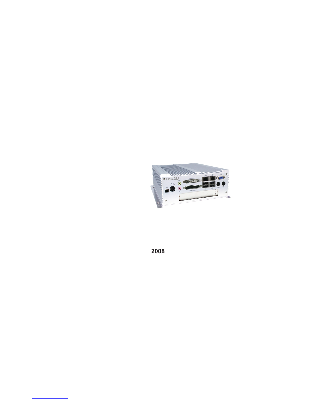
1.1 Product Overview
Featuring Intel 945GME & ICH7 chipsets, the iROBO fan-less box computer
supports Intel’s Core 2 Duo /Celeron M processor with 533/667 MHz FSB and
DDR2 667/533 memory. The rugged iROBO fan-less box computer is
designed for space-critical application requires extreme reliability, low-power
consumption and versatile I/O con.guration. For added .exibility, the iROBO
also boasts three RS232 ports, one RS232/422/485 port and one PCI expansion
slot.
For data storage, the iROBO provides one CompactFlash socket and one 2.5"
HDD drive bay. The System supports ATX mode power feature and can accept a
wide range of power supplies from 12 V DC to 30 V DC.
Housed in a compact 195 mm x 268 mm x 80 mm heavy-duty aluminum chas-
sis, the iROBO is designed for reliable, maintenance-free industrial comput-
ing. The iROBO fan-less box computer offers a cost-effective solution for a
multitude of mission-critical embedded computing applications in automation,
machine control, and POS systems.
Support Intel® Core 2 Duo / Core Duo/ Celeron® M processors
Intel
® 945GME Chipsets
Dual 1000/100/10Mbps LAN ports
6 x USB2.0/ VGA / DVI/ 4 x SIO
One PCI Expansion Slot
w
w
w
w
w
1.2 Block Diagram
DDR2 DIMM Modules
DDR2 533 / 667 MHz
2GB/s
533 / 667
MHz FSB
4 Lanes
Front Panel
Internal Conn.
Intel® Core 2 Duo,
Core Duo,Celeron M
DVI Chrontel
7307
Intel®
945GME
Intel®
ICH7-M DH
0/1
2,3/4/5
CF & IDE
SATA 1
SATA 2
DDR2 Slot
DDR2 Slot
Marvell
88E8053 GbE
RJ45
(LAN1)
PCI-Slot
ALC655
COM3,4
SIO2
IT8712F
DDR2 Channel A
DDR2 Channel B
USB2.0
UltraDMA
33/66/100
SATA
PCIex1 Port (1)
PCI 32 Bit / 33 MHz Bus
LPC BUS
SIO1
IT8712F
LPT
COM1,2
IrDA
KB/MS
GPIO
LVDS
VGA
Marvell
88E8053 GbE
1 x PCIe
Interface
RJ45
(LAN2)
Figure 1.1 : Block Diagram of M/B

12
Chapter 1 General Information
1.3 Specifications
Main Board
M/B
Support Intel® Core 2 Duo, Core Duo, Celeron® M family
processors with 533/667 MHz
Intel® Embedded Processor Reference List (Intel® Longevity CPU):
Core Duo Processor (T2300E) 1.66 G
Core Duo Processor (T2500) 2.0G
Celeron® M 530 1.73G
Celeron® M 440 1.86G
Chipset
Intel® 945GME Graphics Memory Controller Hub (GMCH)
Intel® 82801 GBM ICH7 Mobile digital Home (ICH7-M)
Main Memory
2 x 240 pin DDR2 533/667 DIMM sockets, up to 2 GB unbuffered
non-ECC DDR SDRAM (Max. 3G Capacity supported)
Expansion Slot
Supports one 32-bit/ 33MHz PCI card
PCI Length support:
160 mm (When 2.5" HDD installed)
240 mm (When no HDD is installed)
w
w
w
w
w
w
w
w
I/O Interface-Front
Customized logo(Optional)
HDD Access/Power/LAN status LEDs
2 x USB 2.0 ports
ATX power on/off switch
I/O Interface-Rear
2 x PS/2 connectors (KB/MS)
1 x VGA connector
4 x USB 2.0 ports
2 x GbE LAN Ports
4 x Serial Ports, with 1x DB44 connector ( Three ports support RS232,
one port supports RS232/422/485)
1 x DVI interface
1 x Mic-in and 1 x Speaker-out
1 x 2-pin connector output for remote power on/off switch
DC-in power connector for +12V ~+30V DC power input
Device
1 x On-board CompactFlash socket
1 x Internal 2.5" HDD drive bay
w
w
w
w
w
w
w
w
w
w
w
w
w
w
w
1313
Chapter 1 General Information
Power Input
DC to DC power designed for on-board support of 12 to 30 VDC
(Max: 120 Watts)
1 x External 120 W AC adapter
Power input: 100 to 240 V AC 2 A 50/60 Hz
Power output: 19 VDC
Dimensions
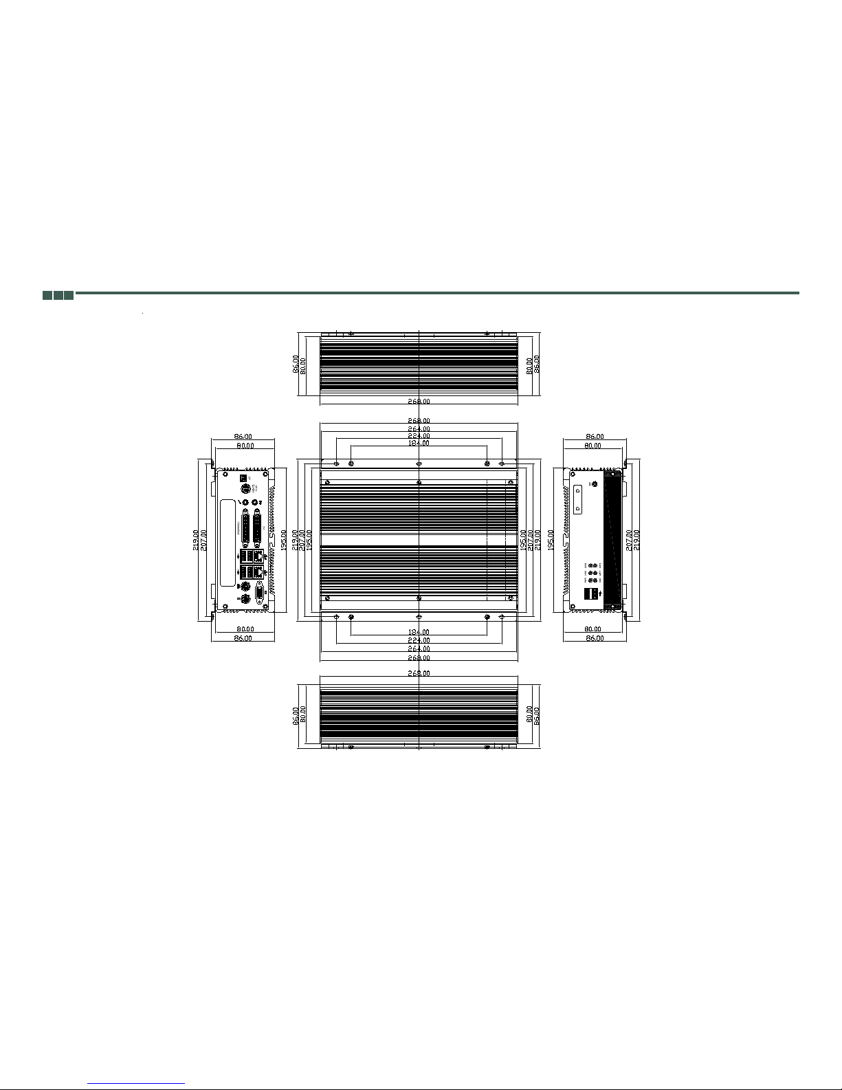
195 mm (W) x 268 mm (D) x 80 mm (H) (7.6" x 10.5" x 3.1")
Construction
Aluminum chassis with fan-less design
Environment
Operating temperature:
Ambient with air .ow : 0°C to 40°C (CPU loading: 70% less continently)
iROBO Tcase ( Surface Temperature of Chassis)
5°C to 50°C (W/HDD)
-10°C to 55°C (W/CF card only)
Storage temperature: -20°C to 80°C
Relative humidity: 10% to 90% (Non-condensing)
Certifications
CE approval
FCC
w
w
w
w
w
w
w
w
w
1.4 Ordering Information
Barebone
iROBO (P/N: 10J0031100X0) RoHS Compliant
Intel
® Core 2 Duo, Core Duo, Celeron® M Fanless Bare-Bone System,
with one PCI expansion slot
1.5 Packing Materials Checklist
DescriptionQ'ty
Power Adapter 120 1
Power Connector 2 1
COM cable
(1 x 44 pin connector to 4 x DB9 ports)
1
IDE Cable1
M/B CD Driver 1
M/B Quick Reference Guide 1
Sliicone Heatsink Compoun 1
hapter 1 General Informatio
n
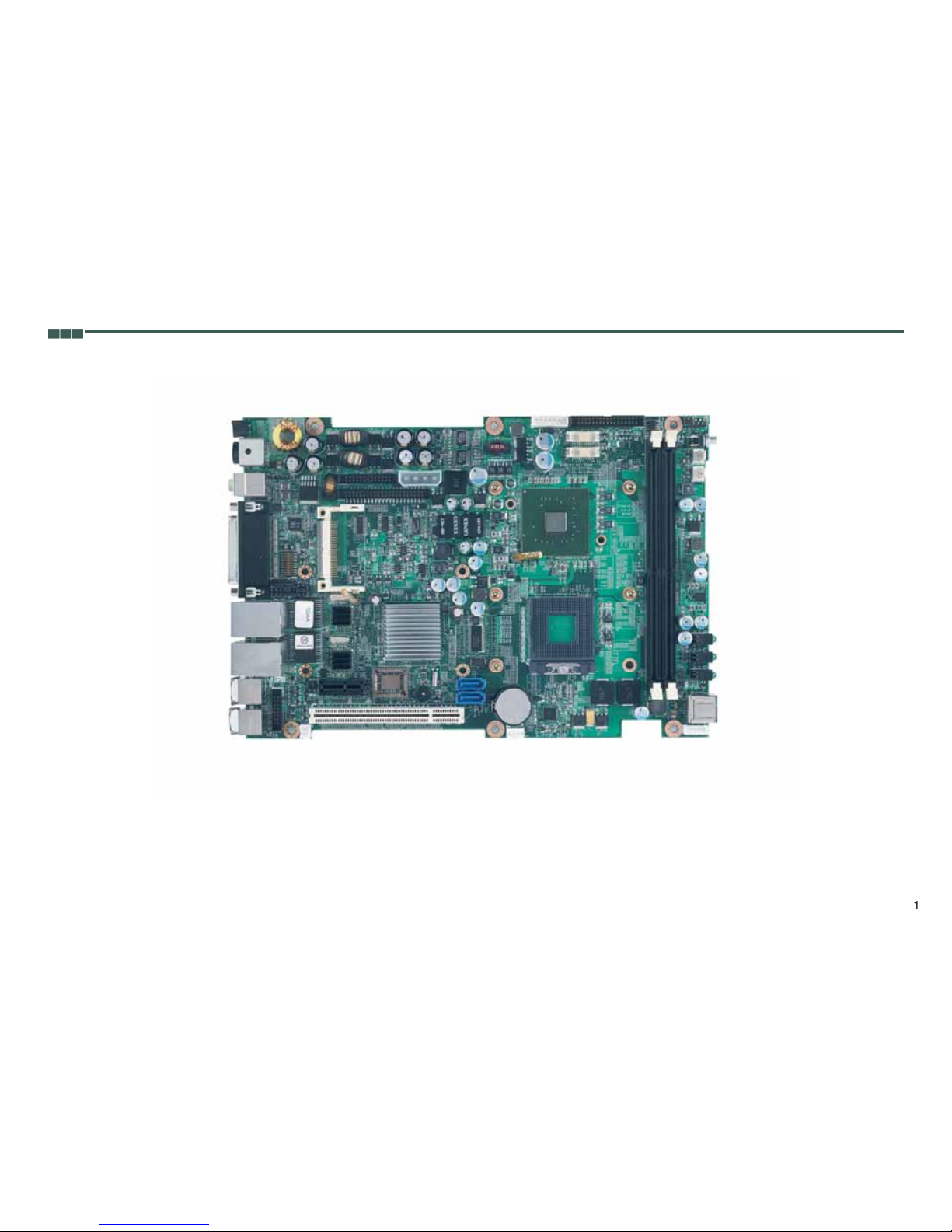
1.6 Board Layout
igure 1.2 Top View of the M/B
1515
Chapter 1 General Information
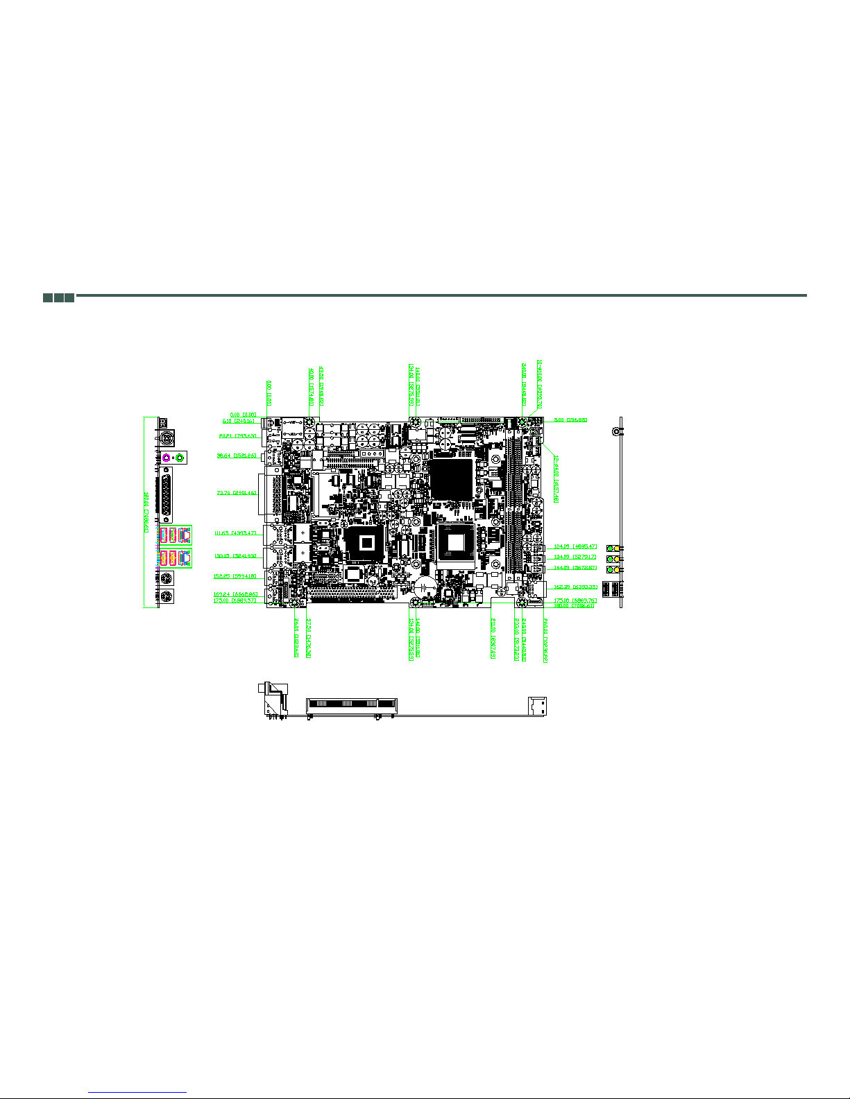
1.7 Dimension Drawing
Figure 1.3: Dimension drawing of M/B
16
Chapter 1 General Information
Figure 1.4 Dimension drawing of iROBO

iROBO
Chapter 2 Jumper Setting
18
Chapter 2 Jumper Setting
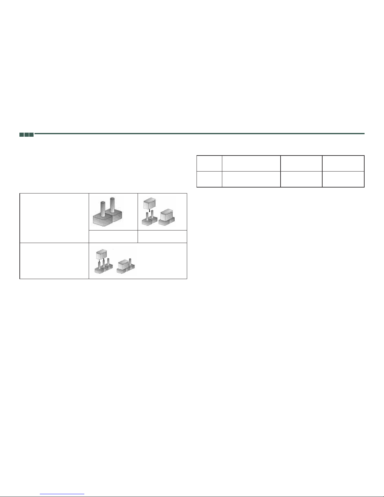
2.1 Setting Jumpers
A jumper is the simplest kind of electric switch. It consists of two metal pins and
a cap. When setting the jumpers, ensure that the jumper caps are placed on the
correct pins. When the jumper cap is placed on both pins, the jumper is SHORT.
If you remove the jumper cap, or place the jumper cap on just one pin, the
jumper is OPEN. Please see the following illustrations
The illustrations on the right show
a 2-pin jumper. When the jumper
cap is placed on both pins, the
jumper is SHORT. If you remove
the jumper cap, or place the
jumper cap on just one pin, the
jumper is OPEN.
Open (Off)Short (On)
These illustrations show a
3-pin Jumper. Pins 1 and 2 are
SHORT.
Table 2.1 Setting Jumpers
2.2 PCI Device interrupt and BUS Assignments
Configuration
BUS/DEVIC/FUNCTION
PCI INT#REQ# /GNT#
PCI Slot11 / 17 / 0
1 / 18 / 0
A,B,C,D
D,A,B,C
0,1
 Loading...