


Laser/Nova
Operating Instructions
Betriebsanleitung
Ref. No 20-8930-0811-03/9608
IRO AB
Box 54
S-523 22 Ulricehamn
Sweden
Tel (int+46) 321 297 00
Fax (int+46) 321 298 00
Telex 36022 iro s
GB/D
English/German

Ref. No 20-8930-0811-03/9608
CONTENTS
INHALT
1
Laser/Nova
Technical specifications ............................................................................................................ 2
Main parts ........................................................................................................................................... 3
Operating diagram ........................................................................................................................ 4
Installation ......................................................................................................................................... 5
Mains connection .......................................................................................................................... 6
Wiring diagram ................................................................................................................................ 9
Motor circuit adjustments ........................................................................................................ 11
Yarn tension ...................................................................................................................................... 12
S/Z Adjustment ............................................................................................................................... 14
Threading ............................................................................................................................................ 15
Tension adjustment ...................................................................................................................... 16
Balloon adjustment ....................................................................................................................... 18
CAT adjustment .............................................................................................................................. 19
Maintenance ..................................................................................................................................... 20
Fault finding ...................................................................................................................................... 21
Technische Spezifikation .......................................................................................... 2
Hauptteile ................................................................................................................. 3
Funktionsdiagramm .................................................................................................. 4
Installation ................................................................................................................ 5
Hauptanschluss ........................................................................................................ 6
Schaltplan ................................................................................................................. 9
Motorschaltkreis-Einstellung .................................................................................... 11
Fadenspannung ........................................................................................................ 12
S/Z-Einstellung ......................................................................................................... 14
Einfädeln ................................................................................................................... 15
Fadenspannung-Einstellung ..................................................................................... 16
Ballon-Einstellung ..................................................................................................... 18
CAT-Einstellung ........................................................................................................ 19
Wartung .................................................................................................................... 20
Fehlersuche .............................................................................................................. 21

WARNING:
CAUTION MUST BE TAKEN IN THE CLOSE VICINITY OF THE FEEDER AS IT CONTAINS
MOVING PARTS THAT CAN CAUSE INJURIES AND, IN NORMAL OPERATION, STARTS
WITHOUT PRIOR WARNING.
ALWAYS TURN OFF THE MAIN SWITCH BEFORE DISCONNECTING OR CONNECTING THE
FEEDER OR ANY OF THE CIRCUIT BOARDS. ALL WORK ON ELECTRICAL COMPONENTS
MUST BE CARRIED OUT BY A QUALIFIED ELECTRICIAN.
TO COMPLY WITH C. E. REGULATIONS ONLY REPLACEMENT PARTS APPROVED BY IRO
AB MAY BE USED
WARNUNG:
DAS VORSPULGERÄT LÄUFT IM NORMALBETRIEB OHNE VORHERIGE WARNUNG AN. ES UMFASST
BEWEGLICHE TEILE, WELCHE VERLETZUNGEN VERURSACHEN KÖNNEN. WENN DAS VORSPULGERÄT EINGESCHALTET IST MUSS IN SEINER UNMITTELBAREN UMGEBUNG MIT VORSICHT
UMGEGANGEN WERDEN.
VOR DEM LÖSEN ODER ERSTELLEN DER ANSCHLÜSSE DES VORSPULGERÄTES ODER EINER DER
KREISLAUFKARTEN IMMER ZUERST DEN HAUPTSCHALTER AUSSCHALTEN. ALLE ARBEITEN AN
ELEKTRISCHEN KOMPONENTEN SIND DURCH EINEN QUALIFIZIERTEN ELEKTRIKER AUSZUFÜHREN.
GEMÄSS C. E. REGELUNGEN DÜRFEN NUR ERSATZTEILE VERWENDET, DIE VON IRO AB FREIGEGEBEN WORDEN SIND.
Ref. No 20-8930-0811-03/9608
TECHNICAL SPECIFICATIONS
TECHNISCHE SPEZIFIKATION
2
Laser/Nova
Laser Nova
135V – 130W – 3ph 80V – 75W – 3ph
Max 1400 m/min Max 1000 m/min
6,5 kg 6,5 kg
Min 10° C – Max 40°C Min 10° C – Max 40°C
Max 95% Max 95%
Max 5mm Max 5 mm
2 Color = 10,5 kg 2 Color = 10,5 kg
4 Color = 12,5 kg 4 Color = 12,5 kg
8 Color = 18 kg 8 Color = 18 kg
m/min

Ref. No 20-8930-0811-03/9608
MAIN PARTS
HAUPTBESTANDSTEILE
3
Laser/Nova
Z
S
Flex Brake
OFF
ON
CAT
Balloon control
adjuster
Stellschraube
für Ballon-Kontrolle
Indicator
Anzeigelampe
S/Z Switch
S/Z Schalter
Mount
Befestigung
Inclined hub
Schrägnabe
Spool body
Spulenkörper
Balloon control brush
Ballon-Kontrollbürste
On-Off Switch
Ein-Aus Schalter
Winding disc
Wickelscheibe
Yarn break detector
Fadenbruchwächter
Yarn store sensors
Garnlagersensor

OPERATING DIAGRAM
FUNKTIONSDIAGRAMM
4
Laser/Nova
Ref. No 20-8930-0811-03/9608
+
+
TB4
TB1
P3 - P10
P1 P1
P1
P2
TB2
TB2
TB2
S/Z
ON/OFF
Motor
Motor
Motor control unit
Motor-Kontrolleinheit
Fuse panel
Sicherungstafel
Machine stop signal
Maschinen-Stopp-Signal
Transformer
Transformator
Mains supply
Hauptanschluss
Yarn store sensor
Garnlagersensor
Yarn store sensor
Garnlagersensor
Yarn break detector
Fadenbruchwächter
S/Z switch
S/Z Schalter
On-Off switch
Ein-Aus Schalter

Ref. No 20-8930-0811-03/9608
The unit should not be mounted
directly onto the weaving machine.
Den Speicher nicht an der Webmaschine befestigen.
Use a separate floor stand.
Separates Gestell verwenden.
Ensure that the mount screws and
locking nuts are correctly
tightened.
Prüfen, ob Befestigungsschrauben
und Kontermuttern angezogen sind.
Max. 32mm
Max. 32mm
INSTALLATION
INSTALLATION
5
Laser/Nova

Ref. No 20-8930-0811-03/9608
MAINS CONNECTION
HAUPTANSCHLUSS
6
Laser/Nova
The power supply to the feeder must
not be disrupted when the weaving
machine stops.
Die Stromversorgung der Speicher
darf durch Stopp der Webmaschine
nicht unterbrochen werden.
Check the wiring diagram before any
connections are carried out.
Vor dem Anschliessen
Verdrahtungsplan prüfen.
L2L1 L3
(N) (N) (N)
L1 L2 L3
1
3
5
2
4
6
(N) (N) (N)
L1 L2 L3
IMPORTANT!
Turn off the main switch before any work is carried out
on the electrical circuit.
WICHTIG !
Hauptschalter oder Netzstecker muss ausgeschaltet sein, bevor Arbeiten
am elektrischen System ausgeführt werden.
Mains supply
Hauptanschluss
Main switch
Hauptschalter
Stop motion relay
Abstell-Relais
Without main switch
Ohne Hauptschalter
With main switch
Mit Hauptschalter

The phase sequence does NOT effect
the direction of rotation.
Phasenfolge hat keinen Einfluss
auf die Drehrichtung des Gerätes.
Variations in main voltage.
Zulässige Netzschwankungen.
Ref. No 20-8930-0811-03/9608
MAINS CONNECTION
HAUPTANSCLUSS
7
Laser/Nova
Connector For volts Hz
Verbindung Für Volt
200/220 Volt 190 – 230 Volt 50/60 Hz
260 Volt 235 - 285 Volt 50/60 Hz
346 Volt 310 - 380 Volt 50/60 Hz
380 Volt 340 - 420 Volt 50/60 Hz
400/415 Volt 365 - 445 Volt 50/60 Hz
440/460 Volt 405 - 495 Volt 50/60 Hz
480/500 Volt 440 - 540 Volt 50/60 Hz
550/575/600 Volt 520 - 630 Volt 50/60 Hz
-+
?
L1L2L3
}

The wiring diagrams on the following page refer to control boxes equipped with a main switch (as
in fig.1 below). The mains supply shall be connected to L1, L2, L3 and EARTH. When the control
box is not equipped with a main switch the mains supply shall be connected as in fig.2.
Das Verdrahtungsdiagramm auf den folgenden Seiten bezieht sich auf die Kontrollkasten mit Hauptschalter (wie in Figur 1 unten). Der Hauptanschluss soll verbunden werden mit L1, L2, L3 und Erde. Wenn der
Kontrollkasten nicht mit einem Hauptschalter ausgerüstet ist, soll der Anschluss wie in Figur 2 abgebildet
erfolgen.
COLOUR
White
Black
Grey
Blue
Yellow
Red
Green
Brown
Orange
Violet
FARBE
Weiss
Schwarz
Grau
Blau
Gelb
Rot
Grün
Braun
Orange
Violett
COULEUR
Blanc
Noir
Gris
Bleu
Jaune
Rouge
Vert
Marron
Orange
Violet
COLOR
Blanco
Negro
Gris
Azul
Amarillo
Rojo
Verde
Marron
Anaranj
Violet
COLORE
Bianco
Nero
Grigio
Blu
Giallo
Rosso
Verde
Marrone
Arancione
Viola
COR
Branco
Negro
Cinzento
Azul
Amarelo
Encarnado
Verde
Castnho
Alaranjado
Violaceo
Ref. No 20-8930-0811-03/9608
MAINS CONNECTION
HAUPTANSCHLUSS
8
Laser/Nova
1
3
5
2
4
6
(N) (N) (N)
L1 L2 L3
(N) (N) (N)
L1 L2 L3
With main switch
Mit Hauptschalter
Common/Erde
Without main switch
Ohne Hauptschalter
Common/Erde

PRIM
135/80V Green P1/5
10/9,5V White P1/1
SEC
R
PRIM
SEC
S
PRIM
SEC
T
1
3
5
2
4
6
L1 L2 L3
L3L2L1
400V / 415V380V200V / 220V 346V
135/80V Green P1/6
10/9,5V White P1/2
135/80V Green P1/7
10/9,5V White P1/3
1
3
5
2
4
6
L1 L2 L3
L3L2L1
550V / 575V / 600V
480V / 500V
440V / 460V
PRIM
135/80V Green P1/5
10/9,5V White P1/1
SEC
R
PRIM
SEC
S
PRIM
SEC
T
135/80V Green P1/6
10/9,5V White P1/2
135/80V Green P1/7
10/9,5V White P1/3
1
3
5
2
4
6
L1 L2 L3
L3L2L1
260V
PRIM
135/80V Green P1/5
SEC
R
PRIM
SEC
S
PRIM
SEC
T
135/80V Green P1/6
135/80V Green P1/7
10/9,5V White P1/1
10/9,5V White P1/2
10/9,5V White P1/3
Ref. No 20-8930-0811-03/9608
WIRING DIAGRAM
SCHALTPLAN
9
Laser/Nova
Common/Erde P1/4
Common/Erde P1/4
Common/Erde P1/4
Mains Supply
Hauptanschluss
Mains Supply
Hauptanschluss
Mains Supply
Hauptanschluss

P2
Max. 24V
123
P2
Earth/Erde
123
P1
C2
C1
S1S2S3
1
P12
C3
234567
S4S5S6
S7
S8S9S10S11S12S13S14
P11
P2
GROUND
SUPPLY
ELTEST
1
1
123
P12
P11
1 1
Ref. No 20-8930-0811-03/9608
FUSE PANEL
SICHERUNGSTAFEL
10
Laser/Nova
Opto coupler, high
Opto-Koppler, Hoch
Opto coupler, low
Opto-Koppler, Tief
4 Colour
4 Farbe
8 Colour / 8 Farbe
Signal to weaving machine
Signal zur Webmaschine
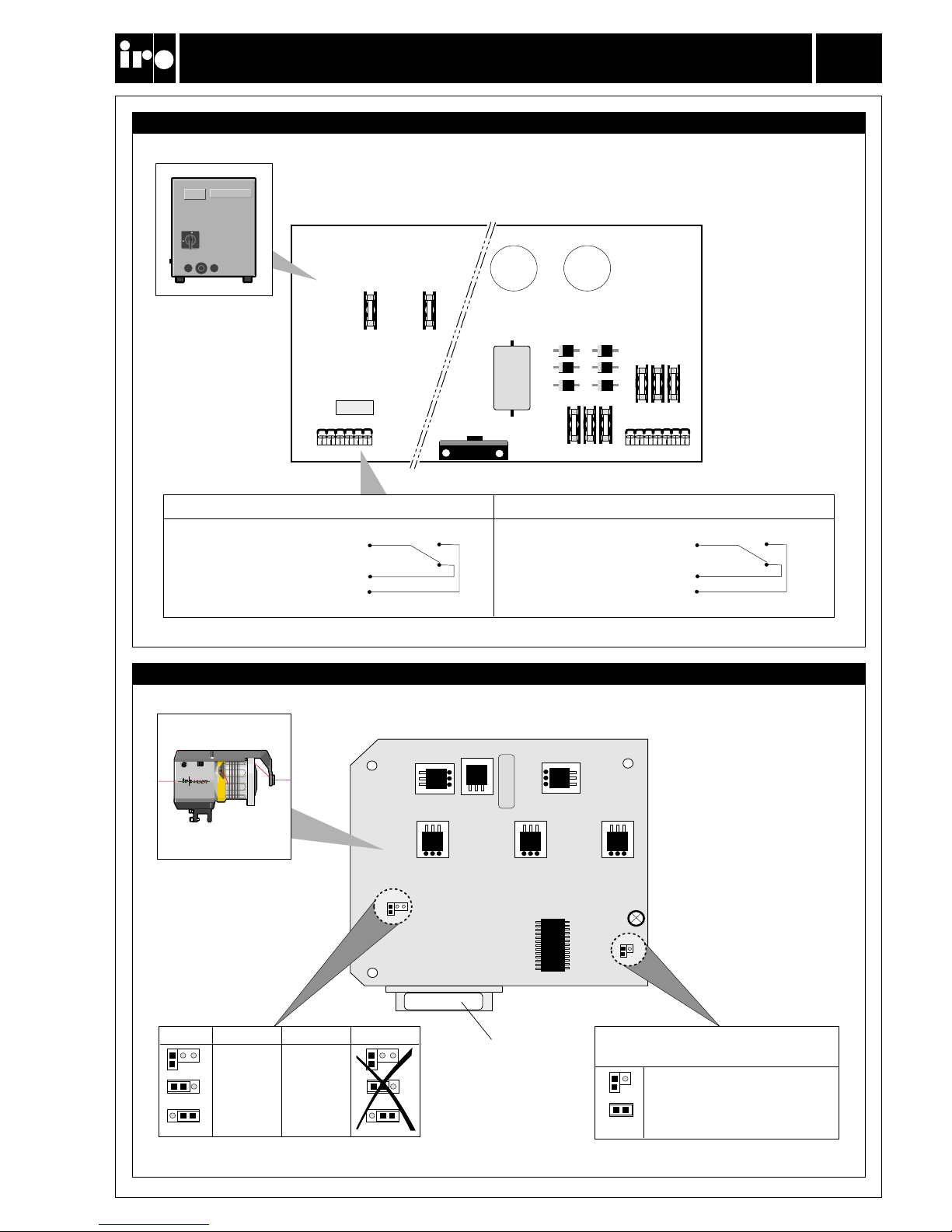
Control box 4729/4829 fuse panel
Kontrollkasten 4729/4829 Sicherungstafel
Stop signal connection to weaving machine / Stopp-Signal Verbindung zur Webmaschine
P2
C1
C2
S1
P1
7
16
S2S3
1
P2
S6S5S4
S1S3
C4
P2
P2
20.9039.00010
02744 930928 P
J2
J1
1 2 3
1 2 3
1 2 3
1400m/min
1000m/min
600m/min
1000m/min
800m/min
500m/min
LASER NOVA 1000
NOVA 600
1 2 3
1 2 3
1 2 3
F L
F L
J2
J1
Ref. No 20-8930-0811-03/9608
MOTOR CIRCUIT ADJUSTMENTS
MOTORSCHALTKREIS-EINSTELLUNG
11
Laser/Nova
Control box 4129/4629 fuse panel
Kontrollkasten 4129/4629 Sicherungstafel
Stop signal connection to weaving machine/Stopp-Signal Verbindung zur Webmaschine
Motor Circuit Board/Motorprintplatte
Part No./ Production date
Teil Nr./Herstellungsdatum
Constant signal/Konstantes Signal
Pulsating signal/Blinkendes Signal
SIGNAL TO WEAVING MACHINE
SIGNAL ZUR WEBMASCHINE
Machine stop / Maschinen-Stopp Stop indicator / Stopp-Anzeige
Common / Abstellsignal - 3
Normally Closed / Schliesser - 2
Normally Open / Öffner - 1
Common / Abstellsignal - 5
Normally Closed / Schliesser - 6
Normally Open / Öffner - 4
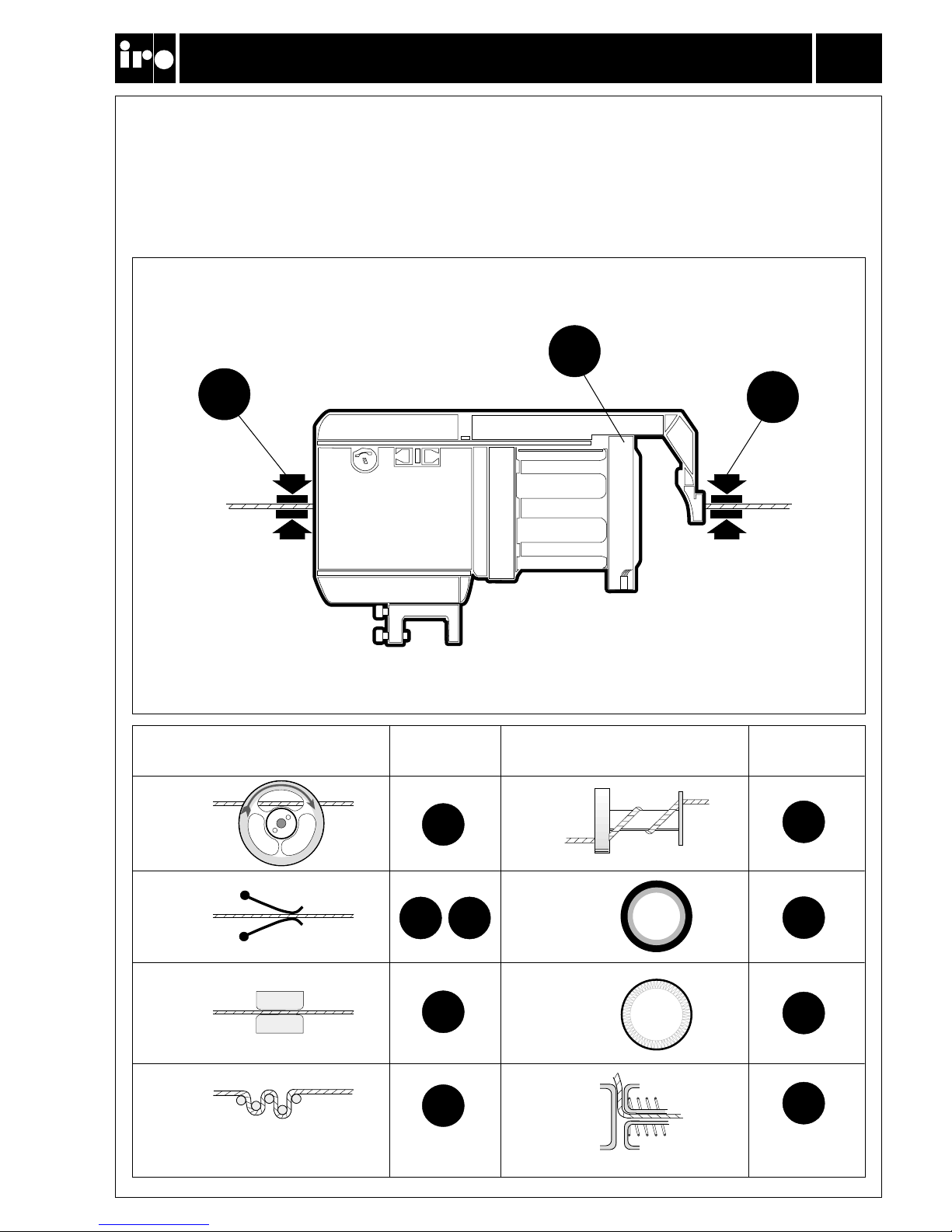
When weaving certain types of yarn and under special weaving conditions it may be necessary to
use yarn tensioners. The table below and on the following page describes suitable combinations.
Bei gewissen Garnen bzw. unter speziellen Bedingungen können Fadenbremsen erforderlich sein.
Die Tabellen unten und auf der nächsten Seite zeigen mögliche Kombinationen.
1
2
3
B
D
E
H
C
A
1
1
1
1
2
3
2
3
1
F
(Flex)
G (Brush)
Ref. No 20-8930-0811-03/9608
TENSIONERS
FADENBREMSEN
12
Laser/Nova
TENSIONER TYPE
FADENBREMS-TYPEN
TENSIONER TYPE
FADENBREMS-TYPEN
POSITION
POSITION
POSITION
POSITION

TENSIONER TABLE
FADENBREMS - TABELLE
13
Laser/Nova
Ref. No 20-8930-0811-03/9608
NOTE: As tensioner performance can be effected by various factors connected to the specific yarns
being used the above recommendations are intended purely as a guide.
In case of any uncertainty it is recommended that a weft insertion test be carried out.
MERKE: Die Wirkungen der Bremsen können durch unterschiedliche Faktoren, in Verbindung
mit den unterschiedlichen Garnen, beeinflusst werden. Daher ist die obige Tabelle lediglich als Richtlinie zu verstehen.
Im Zweifelsfall empfehlen wir die richtige Konstellation durch entsprechende
Schusseintrags-Versuche zu ermitteln.
RAPIER / GREIFER PROJECTILE / PROJEKTIL
Den 2250–1500 1500–450 450– 2250–1500 1500–450 450–
Tex 250–167 167–50 50– 250–167 167–50 50–
Nm 4–66–20 20– 4–66–20 20–
Ne 2,3–3,5 3,5–11,8 11,8– 2,3–3,5 3,5–11,8 11,8–
➊
AAAAAA
FFFFFF
❷
Stiff Medium Soft Stiff Medium Soft
Hart Mittel Weich Hart Mittel Weich
❸
——————
➊
ACCACC
GGGGGG
❷
Medium Medium Soft Medium Soft Soft
Mittel Mittel Weich Mittel Weich Weich
HHH
❸
Stiff Medium Soft
———
Hart Mittel Weich
➊
— D/E D/E — D/E D/E
GG GG
❷
—
Medium Soft
—
Soft Soft
Mittel Weich Weich Weich
❸
—B B———
➊
BBBBBB
FFFGGG
❷
V Stiff Medium Soft V Stiff V Stiff V Stiff
S Hart Mittel Weich S Hart S Hart S Hart
HHH
❸
Stiff Stiff Soft
———
Hart Hart Weich
➊
DBBDBB
FFFGGG
❷
V Stiff Medium Soft V Stiff V Stiff V Stiff
S Hart Mittel Weich S Hart S Hart S Hart
❸
——————
Spun yarns, Cotton,
Wool, Mixed Yarns
Spinnfasern, Baumwolle,
Wolle, Mischgarne.
Elastic Yarns,
Filament Yarns
Elastische Garne,
Filament Garne.
High-Twist Yarns
eg. Crepe
Hochgedrehte Garne,
Crêpe.
Hard Fibres
eg. Linen, Jute
Harte Garne,
Leinen, Jute.
Effect yarns
Effektgarne

Ref. No 20-8930-0811-03/9608
S/Z ADJUSTMENT
S/Z EINSTELLUNG
14
Laser/Nova
Switch off the feeder.
Den Speicher ausschalten.
Revolve the spool body through 90 degrees
(note the position of hole).
Den Spulenkörper um 90° drehen
(Lochposition im Spulenkörper beachten).
Insert the tool in the hole and revolve the winding disc until
the tool locates in the adjusting collar.
Dorn unter leichtem Druck in das Loch des Trommelkörpers einführen
und die Wickelscheibe drehen, bis der Dorn einrastet.
Aligning the winding disc mark with the hole in the spoolbody
gives the zero separation position. To adjust, hold the tool in
position and revolve the winding disc in the appropriate direction. The separation increase from 0 - 2.1 mm the more the disc
is rotated.
Durch Drehen der Wickelscheibe nach S oder Z stellen Sie die
Drehrichtung ein. Der Dorn muss hierbei eingerastet bleiben. Die
Separierung ist variabel von 0 - 2,1 mm und hängt davon ab, um wieviel
die Wickelscheibe verdreht wird.
Return the spool body to its original position. Set the direction
of rotation with the switch (A).
Spulenkörper in Arbeitsstellung zurückdrehen (Abtaster oben).
Motordrehrichtung an Schalter (A) einstellen.
OFF ON
S
Z
O
O
O
O
z
s
OFF ON
ZS
S
Z
A

OFF ON
S
Z
11
✗
*
OK!
Ref. No 20-8930-0811-03/9608
THREADING
EINFÄDELN
15
Laser/Nova
Without CAT
Switch off the feeder.
Align the winding disc eyelet (1) and thread the needle all the
way through the feeder and output eyelet.
Pull the yarn through and restart the feeder.
Ohne CAT
Speicher ausschalten. Wickelscheibe in die richtige Position drehen(1).
Die Einfädel-Nadel durch den Speicher, einschliesslich Auslauföse,
stossen. Faden in Nadel einhängen und durchziehen.
Speicher starten.
* With Flex-Brake; Damage may be caused if the feeder is
incorrectly threaded.
* Mit Flex-Brake; Beschädigung kann durch unsachgemässes Einfädeln des Speichers verursacht werden.
With CAT
Switch off the feeder and align the winding disc eyelet .
Thread the needle through the feeder and balloon control
brush. Start the feeder and fill the yarn store. Insert the
threading needle into the CAT (1) as far as possible. Pulling
the yarn (2) will cause it to wrap around the threading needle.
Mit CAT
Speicher ausschalten. Wickelscheibe in die richtige Position
drehen. Speicher starten und Garnlager aufwickeln. EinfädelNadel von vorne, bis zum Anschlag in die CAT einführen (1).
Durch Ziehen am Faden (2) wird dieser in die Nadel eingehängt
When the threading needle is pulled out (3) the yarn will follow.
Mit der Nadel wird der Faden aus der Bremse gezogen (3).
OFF ON
S
Z
11
✗
*
OK!

Ref. No 20-8930-0811-03/9608
INPUT TENSIONER ADJUSTMENT
EINSTELLUNG DER EINLAUFBREMSE
16
Laser/Nova
Yarn store formation.
Lage der Garnwindungen.
???
Type of yarn.
Garn-Typ.
Adjust input tension.
Einlaufspannung einstellen.
Coarse/Grob
Fine/Fein
?
✓✓
Excessive yarn separation on fine
yarns may cause false stops.
Übermässige Fadenseparierung kann bei
dünnen Garnen falsche Stopps
verursachen.
✗
✓

Ref. No 20-8930-0811-03/9608
TENSIONER ADJUSTMENT
EINSTELLUNG DER BREMSE
17
Laser/Nova
To enable regulation of the tensioning
disc rotation speed on the disc
tensioner, the mounting plate is
equipped with a slot. Loosening the
locating screw (A) and adjusting the
disc assembly towards B will reduce
the rotation speed. Adjusting the disc
assembly towards C will increase the
rotation speed.
Bei der Fadenbremse lässt sich die
Umdrehungs- geschwindigkeit der
Bremsscheiben regulieren. Hierzu ist die
Halterung mit einem Schlitz versehen. Wird
die Schraube (A) gelöst, und die Bremse in
Richtung (B) verschoben, verringert sich
die Geschwindigkeit. Eine Verschiebung in
Richtung (C), erhöht diese.
When weaving yarns with a very high
friction coefficient the above
adjustment may not be adequate to
reduce the speed to an acceptable
level. In such cases the metal washer
(D) under the lower disc should be
replaced by one of the rubber washers
(E) located behind the balloon breaker.
The metal washer can then be stored
on the plastic pin and a rubber washer
placed in front of it to keep it in place.
Bei Garnen mit sehr hohem
Reibungskoeffizienten, reicht eventuell obige
Einstellung nicht aus, um die
Umdrehungsgeschwindigkeit auf ein
akzeptables Niveau zu bringen. In solchen
Fällen wird die Metallscheibe (D) unter der
unteren Bremsscheibe durch eine
Gummischeibe (E) ersetzt. Diese befindet
sich auf der Innenseite der Ballonkontrollscheibe. Die Metallscheibe wird zum
Aufbewahren auf den Plastikstift gesteckt
und durch eine Gummischeibe gesichert.
B
C
D
E
A
Side view / Seitenansicht
Top view / Aufsicht

Ref. No 20-8930-0811-03/9608
BALLOON/FLEX BRAKE ADJUSTMENT
BALLON/FLEX BRAKE-EINSTELLUNG
18
Laser/Nova
Brush rings: Goat hair = Soft
Cow hair = Medium
Pig bristle = Stiff
Polyamide = Very stiff
Bürstenringe: Ziegenhaar = Weich
Kuhhaar = Mittel
Schweineborste = Hart
Polyamid = Sehr hart
The type of brush ring / Flex Brake
depends on the yarn that is to be used.
Der Typ des Bürstenringes / Flex Brake
hängt vom Garn ab.
Adjust the balloon control/Flex Brake
tension
Note: Flex Brake adjustment latitude
is max 5 revolutions of the adjustment
screw from the point where the brake
touches the spool body (point A).
Einstellung des Bürstenringes / Flex BrakeSpannung.
Beachte: Der Bürstenring dient der
Ballonkontrolle. Seine Position kann je nach
Garnstärke über die Regulierschraube -/+
eingestellt werden. Der Spielraum für die
Einstellung der Flex Brake beträgt maximal
5 Umdrehungen der Regulierschraube von
der Position an, wo die Bremse den
Spulenkörper berührt (A).
?
OK!
+
-
+
- -
+
-
A
Brush Ring/Bürstenring Flex-Brake
Coarse/Grob
V.stiff/Sehr hart Stiff/Hart Medium/Mittel
Stiff/Hart Medium/Mittel Soft/Weich
Soft/Weich
Fine/Fein

Ref. No 20-8930-0811-03/9608
CAT ADKISTMENT
CAT-EINSTELLUNG
19
Laser/Nova
Control input yarn tension to the CAT.
Reguliere die Faden-Einlaufspannung in
die CAT.
Adjustment of the output tension.
Einstellung der Faden-Auslaufspannung.
OK!
+
-
+
-
g

Ref. No 20-8930-0811-03/9608
MAINTENANCE
WARTUNG
20
Laser/Nova
It is recommended to carry out a
periodical cleaning of any lint or dust
accumulation on the feeder or the
control box.
Eine periodische Säuberung von Speichergerät und Kontrollkasten ist empfehlenswert, um Faserflug und Schmutzansammlungen zu verhindern.
The unit requires no extra lubrication.
Schmierung ist nicht erforderlich.
Always turn off the main switch or
isolate the power supply before
connecting or disconnecting the
feeder, the control board or any of the
circuit boards.
Hauptschalter oder Netzstecker
ausschalten, bevor Verbindungskabel
befestigt oder gelöst wird oder sonstige
Arbeiten am Kontrollkasten ausgeführt
werden.
Main switch
Hauptschalter
1
0

Ref. No 20-8930-0811-03/9608
FAULT FINDING
FEHLERSUCHE
21
Laser/Nova
Fault Check in the following order
The feeder will not start 3 ➔ 5 ➔ 13 ➔ 4 ➔ 1 ➔ 2 ➔ 8 ➔ 9 ➔ 7
The feeder will not stop 14 ➔ 13 ➔ 9 ➔ 8
The yarn reserve runs out 15 ➔ 13 ➔ 5 ➔ 9 ➔ 8 ➔ 11
Irregular motor speed 13 ➔ 14 ➔ 8 ➔ 9 ➔ 17
Fuses S1 - S14 in control box blow repeatedly 5 ➔ 8
Feeder warning indicator flashes 10 ➔ 5 ➔ 12 ➔ 6 ➔ 16 ➔ 17
1. Check mains supply.
2. Check fuses S1 - S14.
3. Ensure correct spool body position.
4. Check cable connections.
5. Check that the winding disc runs free.
6. Check that the motor is not overheated (the thermal switch will cut out)
7. Replace fuse board in control box.
8. Replace motor circuit board.
9. Replace yarn store sensor unit.
10. Input yarn break.
11. Check stop signal connection between control box and weaving machine.
12. Strong yarn trapped at input side.
13. Check that the sensor magnets move freely
14. Input yarn tension too low.
15. Check the max, motor speed setting
16. Low motor voltage.
17. Excessive yarn separation on fine yarns.
Fehler Prüfen in folgender Reihenfolge
Gerät startet nicht 3 ➔ 5 ➔ 13 ➔ 4 ➔ 1 ➔ 2 ➔ 8 ➔ 9 ➔ 7
Gerät stoppt nicht 14 ➔ 13 ➔ 9 ➔ 8
Garnreserve läuft leer 15 ➔ 13 ➔ 5 ➔ 9 ➔ 8 ➔ 11
Falsche Motor-Geschwindigkeit 13 ➔ 14 ➔ 8 ➔ 9 ➔ 17
Sicherung S1 - S14 im Kontrollkasten schlägt durch 5 ➔ 8
Speicher-Anzeigelampe blinkt 10 ➔ 5 ➔ 12 ➔ 6 ➔ 16 ➔ 17
1. Hauptanschluss prüfen
2. Sicherungen S1 - S14 prüfen
3. Richtige Stellung der Trommel prüfen
4. Kabel-Verbindungen prüfen.
5. Prüfe, ob Wickelscheibe frei läuft.
6. Prüfe, ob Motor überhitzt ist (Wärmeschalter schaltet ab)
7. Sicherungstafel austauschen.
8. Motorprint austauschen
9. Garnsensor-Einheit austauschen
10. Fadenbruch am Einlauf.
11. Stopp-Signal-Verbindung zwischen Kontrollkasten und Webmaschine prüfen.
12. Faden verhängt auf der Einlaufseite.
13. Prüfe ob Sensormagnete frei beweglich sind.
14. Einlauffadenspannung zu niedrig.
15. Überprüfe die Einstellung der Motor-Endgeschwindigkeit
16. Motorspannung zu niedrig.
17. Übermässige Fadenseparierung bei dünnen Garnen.
 Loading...