

Iriss Sonus PD Operating Manual

Operating Manual
Sonus PD Ultrasonic Detector

Sonus PD Ultrasonic Detector2
Distribution:
Model:
Type:
IRISS Inc.
Ultrasonic Detector
Sonus PD Multifunction device for leak detection, tightness control and other maintenance tasks
IRISS Inc.
10306 Technology Terrace
Bradenton, FL 34211
Phone: +1 (941) 907-9128
E-mail: info@iriss.com
Web: http://www.iriss.com
© 2017 IRISS Inc. All rights reserved
The contents of this manual are copyrighted property. Duplication and distribution in any form, particularly reprinting,
photographic, mechanical or electronic reproduction, or in the form of storage in data processing systems or data
networks, is prohibited without the consent of the copyright holder.
Revision: 1.0, Date: 2017-03-15 Subject to technical modications!
Sonus PD Ultrasonic Detector 3
07
1 The Sonus PD
2 Partial Discharge
2.1 Electromagnetic Waves
2.1.1 Electromagnetic Waves
2.1.2 Acoustic Emissions
3 Physical Dimensions Of Sonus PD
3.1 Dimensions
3.2 Weight
3.3 Power Supply
3.4 Temperature
3.5 Relative Humidity
3.6 IP Rating
4 CE Compliance
5 Sonus PD Kit List
6 General Substation Safety Precautions
6.1 Access
6.2 Visual Inspection Of Substation
7 Environmental Protection
8 Sonus PD Overview
8.1 Sonus PD Outline
07
06
07
07
08
08
08
08
08
08
08
10
10
11
11
11
10
09
09
Contents
Sonus PD Ultrasonic Detector4
12
8.2 Sonus PD Input/ Output
9 Transient Earth Voltage (TEV)
9.1 Capacitive Coupler Sensor
9.2 Specication
10 Acoustic Emission (AE)
10.1 Surface Tracking
10.2 Acoustic Sensor
10.3 Specication
11 Operational Control
11.1 Control Buttons
11.2 Power
11.2.1 Battery Level
11.3 Operating Modes
11.3.1 TEV Modes
11.3.2 TEV Noise Detection
11.3.3 AE Mode
11.4 Display
11.4.1 Level Display
11.5 Sonus PD App
11.5.1 Sonus PD App Introduction
11
13
13
13
13
14
14
15
14
14
16
16
15
19
17
17
12
12
19
Contents Cont.

Sonus PD Ultrasonic Detector 5
11.5.2 Combined Functionality
12 Check Sonus PD Function
12.1 Function Tester
12.2 Check The TEV Function
12.3 Check The AE Function
13 Surveying Switchgear Panels For PD- TEV
13.1 Step 1- Check TEV Activity Levels
13.1.1 Example 1 – Component Switchgear
13.1.2 Example 2 – Fully Enclosed Switchgear
13.2 Step 2- Verify Whether Detected Activity is Noise or PD
14 Surveying Switchgear Panels For PD- TEV
14.1 Step 1- Check Acoustic Emissions Activity Levels
15 Appendix A: Example Test Sheet
16 Appendix B: The Relationship Between PD and Criticality
21
22
21
21
23
24
24
23
25
26
26
27
28
19
Contents Cont.
Sonus PD Ultrasonic Detector 6
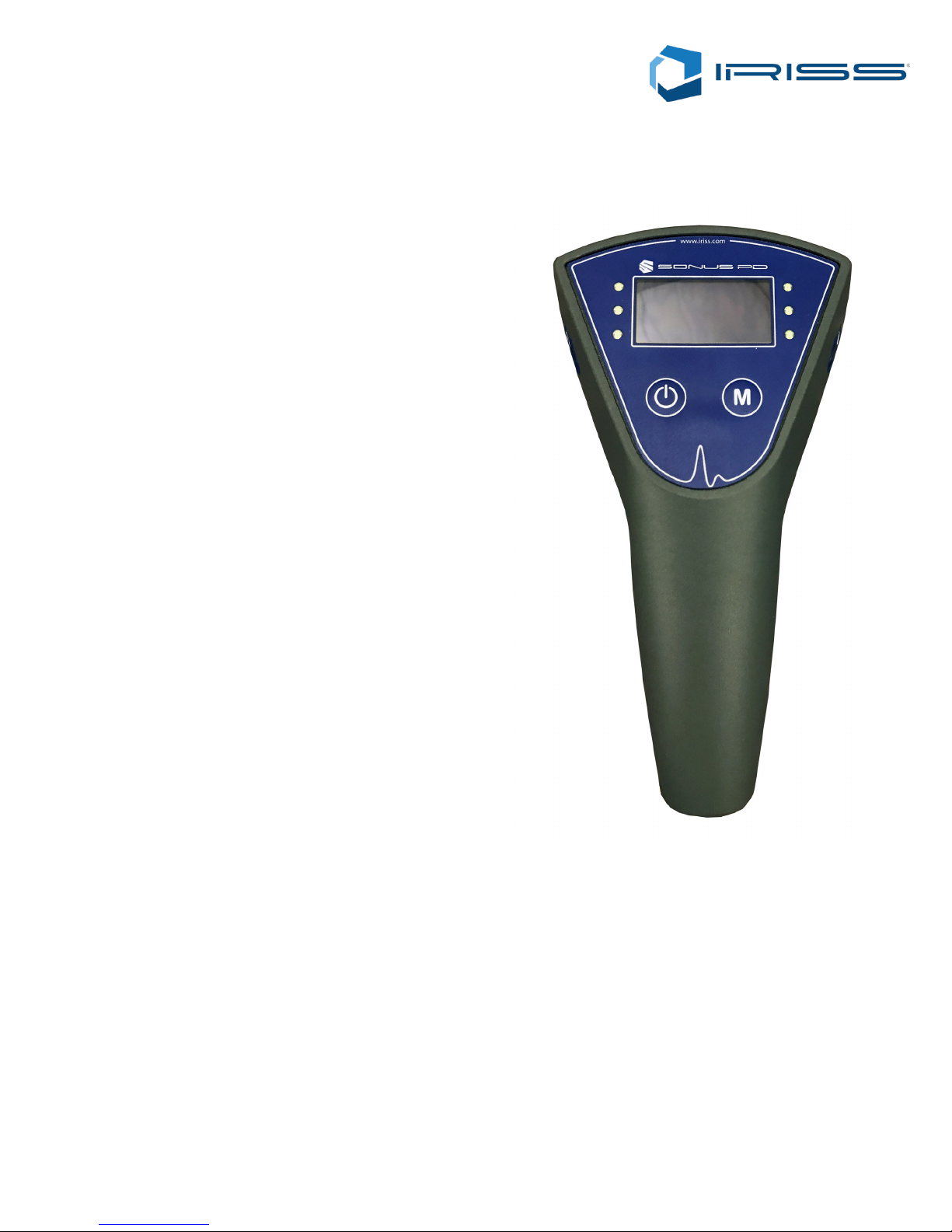
The Sonus PD is a rst level partial discharge (PD)
detection instrument designed for use both in distribution
voltage substations and HV Switchyards. It enables
Network Operators to carry out simple routine tests that will
identify discharge activity in switchgear and accessories.
The battery powered portable device has a live display that
shows a quantied level of detected PD activity. A colour
coded trac light system indicates when detected levels
exceed the pre-set thresholds.
The Sonus PD has a built in TEV sensor for capacitive
coupling to switchgear and a built in ultrasonic sensor for
detection of surface discharge and tracking. Headphones
are also supplied to help the user when working in noisy
environments.
The Sonus PD is supplied with a battery operated Function
Tester that should be used to verify the correct operation of
the instrument before use.
The Sonus PD is a non-intrusive test device therefore PD
can be identied and located whilst the equipment remains
live.
1 The Sonus PD

Sonus PD Ultrasonic Detector7
Partial Discharge (PD) is an electrical discharge that does not completely bridge the space between two conducting
electrodes. The discharge may be in a gas lled void in a solid insulating material, in a gas bubble in a liquid insulator or
around an electrode in a gas. When partial discharge occurs in a gas, it is usually known as corona.
Partial discharge is generally accepted as the predominant cause of long term degradation and eventual failure of
electrical insulation. As a result, its measurement is standard as part of the factory testing of most types of high voltage
equipment. In-service monitoring of equipment for PD gives an advance warning of pending insulation failure. This allows
a plant operator to take remedial action during planned outages.
Partial discharge often occurs under normal working conditions, gradually deteriorating the dielectric until it can no longer
withstand the electrical stress and fails. Levels of PD activity will measure as insulating materials degrade. By detecting
this PD activity while the equipment is in operation, failure can be avoided.
A PD event will radiate energy in different forms and this energy can be picked up by the Sonus PD in order to detect the
source and locate it.
PD creates EM radiation that dissipates in all directions away from the source. Metal components, for instance the panels
around switchgear, will pick up this radiation and small voltages called Transient Earth Voltages (TEVs) are induced on
the surface. These very high frequency signals will be picked up by the Sonus PD and indicate that there is a PD source
nearby.
Partial Discharge also generates acoustic emissions energy across a wide band of frequencies. This acoustic energy can
be detected in the ultrasonic range when there is a ‘line of sight’ between the PD source and the detecting sensor. Sharp
points, for instance on air insulated cable terminations, are typical sources of corona that will produce acoustic emission.
Cast insulators are prone to Surface Tracking where electrical stress across the insulator’s surface causes discharge, and
deteriorates the insulator surface and creates carbon tracks. This can lead to ashover and failure of the equipment
2.1.2 Acoustic Emmissions (AE)
2 Partial Discharge
2.1 Radiated Energy
2.1.1 Electromagnetic Waves (EM)

Sonus PD Ultrasonic Detector 8
The Sonus PD has the following external dimensions excluding the carry bag:
• Width: 190 mm
• Height: 90 mm
• Depth: 65 mm
The Sonus PD weighs 300g.
3.3 Power Supply
The Sonus PD has a built in Lithium-Ion battery allowing for long battery life. A battery charger and car charger is included
in the kit.
The Sonus PD Field Detector can be used in the following temperature ranges:
• Operation: 0°C to +55°C
• Storage: -20°C to +75°C
3.5 Relative Humidity
The Field Detector can be used in the following relative humidity ranges:
• Operation: 0% to 90%
3.4 Temperature
The SONUS PD is IP54 rated but is not intended for use in damp conditions.
3.6 IP Rating
Test Situation Est. Battery Life
Sonus PD Only 5 hours
Sonus PD with App 6 hours
3 Physical Dimensions of Sonus PD
3.1 Dimensions
3.2 Weight
Sonus PD Ultrasonic Detector 9
The Sonus PD system complies with the following directives:
EN 61000-6-2: 2005 Immunity Standard (Industrial Environment)
EN 61000-6-3: 2007 Emission Standard (Residential, Commercial and Light Industry Environment)
4 CE Compliance
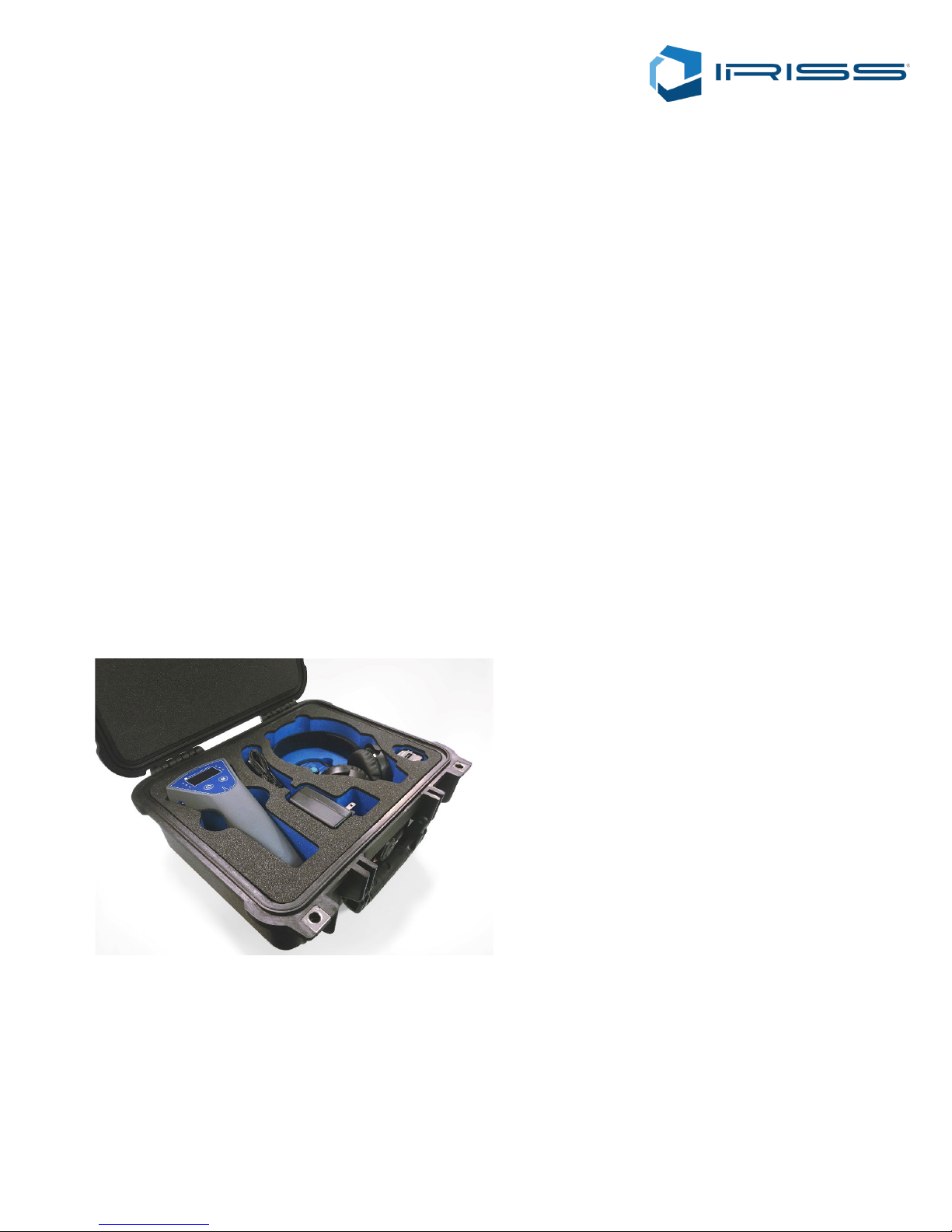
The Sonus PD Kit includes:
• 1 x Sonus PD
• 1 x Sonus PD power supply / charger unit
• 1 x USB Charger Cable
• 1 x Car Charging Adapter
• 1 x 3.5mm stereo headband Headset
• 1 x PD-FT Function Tester
• 1 x Moulded carry case
• 1 x Sonus PD Manual
• 1 x Sonus PD Companion App Manual
5 Sonus PD Kit List
 Loading...