

IRIS Net TPI-8, TPI-12 Owner's Manual

OWNER’S MANUAL
BEDIENUNGSANLEITUNG
MODE D’EMPLOI
TPI-8 / TPI-12
8.4“ / 12.1“ Touch Panels

2 TPI-8 / TPI-12 Touch Panel
CONTENTS
Introduction . . . . . . . . . . . . . . . . . . . . . . . . . . . . . . . . . . . . . . . . . . . . . . . . . 6
Overview . . . . . . . . . . . . . . . . . . . . . . . . . . . . . . . . . . . . . . . . . . . . . . . 6
Scope of Supply & Warranty . . . . . . . . . . . . . . . . . . . . . . . . . . . . . . . . 6
IRIS-Net™ . . . . . . . . . . . . . . . . . . . . . . . . . . . . . . . . . . . . . . . . . . . . . . 7
Installation . . . . . . . . . . . . . . . . . . . . . . . . . . . . . . . . . . . . . . . . . . . . . . . . . . 8
Connections and Controls . . . . . . . . . . . . . . . . . . . . . . . . . . . . . . . . . . 8
Mounting and Initial Operation . . . . . . . . . . . . . . . . . . . . . . . . . . . . . . . 9
Initial Operation . . . . . . . . . . . . . . . . . . . . . . . . . . . . . . . . . . . . . . . . . . 11
Editing of network configuration. . . . . . . . . . . . . . . . . . . . . . . . . . . . 11
Updating the IRIS-Net project file or application . . . . . . . . . . . . . . . 15
Editing of screen saver and display backlight configuration . . . . . . 17
Maintenance & Care . . . . . . . . . . . . . . . . . . . . . . . . . . . . . . . . . . . . . . 19
Replacing the Lithium Battery . . . . . . . . . . . . . . . . . . . . . . . . . . . . . 19
Appendix . . . . . . . . . . . . . . . . . . . . . . . . . . . . . . . . . . . . . . . . . . . . . . . . . . . . 22
Example of use . . . . . . . . . . . . . . . . . . . . . . . . . . . . . . . . . . . . . . . . . . 22
Troubleshootings . . . . . . . . . . . . . . . . . . . . . . . . . . . . . . . . . . . . . . . . . 22
Using multiple Touch Panels at a Ethernet . . . . . . . . . . . . . . . . . . . 22
INHALT
Einführung . . . . . . . . . . . . . . . . . . . . . . . . . . . . . . . . . . . . . . . . . . . . . . . . . . 29
Überblick . . . . . . . . . . . . . . . . . . . . . . . . . . . . . . . . . . . . . . . . . . . . . . . 29
Lieferumfang & Garantie . . . . . . . . . . . . . . . . . . . . . . . . . . . . . . . . . . . 29
IRIS-Net™ . . . . . . . . . . . . . . . . . . . . . . . . . . . . . . . . . . . . . . . . . . . . . . 30
Installation . . . . . . . . . . . . . . . . . . . . . . . . . . . . . . . . . . . . . . . . . . . . . . . . . . 31
Anschlüsse und Bedienelemente . . . . . . . . . . . . . . . . . . . . . . . . . . . . . 31
Montage . . . . . . . . . . . . . . . . . . . . . . . . . . . . . . . . . . . . . . . . . . . . . . . . 32
Inbetriebnahme . . . . . . . . . . . . . . . . . . . . . . . . . . . . . . . . . . . . . . . . . . 34
Netzwerkeinstellung konfigurieren . . . . . . . . . . . . . . . . . . . . . . . . . . 34
Aktualisieren der Projekt-Datei bzw. IRIS-Net . . . . . . . . . . . . . . . . . 38
Bildschirmschoner und Hintergrundbeleuchtung konfigurieren . . . . 41
Wartung & Pflege . . . . . . . . . . . . . . . . . . . . . . . . . . . . . . . . . . . . . . . . . 42
Ersetzen der Lithium-Batterie . . . . . . . . . . . . . . . . . . . . . . . . . . . . . 43
Anhang . . . . . . . . . . . . . . . . . . . . . . . . . . . . . . . . . . . . . . . . . . . . . . . . . . . . . 45
Anwendungsbeispiel . . . . . . . . . . . . . . . . . . . . . . . . . . . . . . . . . . . . . . 45
Problemlösungen . . . . . . . . . . . . . . . . . . . . . . . . . . . . . . . . . . . . . . . . . 45
Mehrere Touch Panels an einem Ethernet . . . . . . . . . . . . . . . . . . . 45

TPI-8 / TPI-12 Touch Panel 3
MATIÈRES
Introduction . . . . . . . . . . . . . . . . . . . . . . . . . . . . . . . . . . . . . . . . . . . . . . . . . 53
Généralités . . . . . . . . . . . . . . . . . . . . . . . . . . . . . . . . . . . . . . . . . . . . . . 53
Éléments fournis et garantie . . . . . . . . . . . . . . . . . . . . . . . . . . . . . . . . 53
IRIS-Net™ . . . . . . . . . . . . . . . . . . . . . . . . . . . . . . . . . . . . . . . . . . . . . . 54
Installation . . . . . . . . . . . . . . . . . . . . . . . . . . . . . . . . . . . . . . . . . . . . . . . . . . 55
Connexions et commandes . . . . . . . . . . . . . . . . . . . . . . . . . . . . . . . . . 55
Montage et mise en route . . . . . . . . . . . . . . . . . . . . . . . . . . . . . . . . . . 56
Opérations initiales . . . . . . . . . . . . . . . . . . . . . . . . . . . . . . . . . . . . . . . . 58
Modification de la configuration réseau . . . . . . . . . . . . . . . . . . . . . . 58
Mise à jour du fichier de projet ou de l’application IRIS-Net . . . . . . 62
Modification de la configuration de l’économiseur d’écran. . . . . . . . 65
Maintenance et entretien . . . . . . . . . . . . . . . . . . . . . . . . . . . . . . . . . . . 66
Remplacement de la pile au lithium . . . . . . . . . . . . . . . . . . . . . . . . . 67
Annexe . . . . . . . . . . . . . . . . . . . . . . . . . . . . . . . . . . . . . . . . . . . . . . . . . . . . . 69
Exemples d’utilisation . . . . . . . . . . . . . . . . . . . . . . . . . . . . . . . . . . . . . . 69
Résolution des pannes . . . . . . . . . . . . . . . . . . . . . . . . . . . . . . . . . . . . . 69
Fonctionnement en Ethernet avec des écrans tactiles . . . . . . . . . . 69
Specification . . . . . . . . . . . . . . . . . . . . . . . . . . . . . . . . . . . . . . . . . . . . . . . . . 71
Dimensions . . . . . . . . . . . . . . . . . . . . . . . . . . . . . . . . . . . . . . . . . . . . . 72
Declaration of Conformity . . . . . . . . . . . . . . . . . . . . . . . . . . . . . . . . . . . 74
FCC Statement . . . . . . . . . . . . . . . . . . . . . . . . . . . . . . . . . . . . . . . . . . 75
4
TPI-8 / TPI-12 Touch Panel
Owner’s manual
IMPORTANT SAFETY INSTRUCTIONS
1. Read these instructions.
2. Keep these instructions.
3. Heed all warnings.
4. Follow all instructions.
5. Do not use this apparatus near water.
6. Clean only with a dry cloth.
7. Do not block any ventilation openings. Install in accordance with the manufacture’s instructions.
8. Do not install near heat sources such as radiators, heat registers, stoves, or other apparatus (including
amplifiers) that produce heat.
9. Do not defeat the safety purpose of the polarized or the grounding-type plug. A polarized plug has two
blades with one wider than the other. A grounding type plug has two blades and a third grounding
prong. The wide blade or the third prong are provided for your safety. If the provided plug does not fit
into your outlet, consult an electrician for replacement of the obsolete outlet.
10. Protect the power cord from being walked on or pinched particularly at plugs, convenience
receptacles, and the point where they exit from the apparatus.
11. Only use attachments/accessories specified by the manufacturer.
12. Use only with the cart, tripod, bracket, or table specified by the manufacturer, or sold with the
apparatus. When a cart is used, use caution when moving the cart/apparatus combination to avoid
injury from tip-over.
13. Unplug this apparatus during lightning storms or when unused for a long period of time.
14. Refer all servicing to qualified service personnel. Servicing is required when the apparatus has been
damaged in any way, such as power-supply cord or plug is damaged, liquid has been spilled or objects
have fallen into the apparatus, the apparatus has been exposed to rain or moisture, does not operate
normally, or has been dropped.
The lightning flash with arrowhead symbol, within an equilateral triangle is intended to alert the user to the presence of uninsulated
“dangerous voltage“ within the product’s enclosure that may be of
sufficent magnitude to constitute a risk of electric shock to persons.
The exclamation point within an equilateral triangle is intended to
alert the user to the presence of important operating and maintenance (servicing) instructions in the literature accompanying the
appliance.

5
TPI-8 / TPI-12 Touch Panel
Owner’s manual
15. Do not expose this equipment to dripping or splashing and ensure that no objects filled with liquids,
such as vases, are placed on the equipment.
16. To completely disconnect this equipment from the AC Mains, disconnect the power supply cord plug
from the AC receptacle.
17. The mains plug of the power supply cord shall remain readily operable.
IMPORTANT SERVICE INSTRUCTIONS
CAUTION: These servicing instructions are for use by qualified personnel only. To reduce
the risk of electric shock, do not perform any servicing other than that contained in
the Operating Instructions unless you are qualified to do so. Refer all servicing to
qualified service personnel.
1. Security regulations as stated in the EN 60065 (VDE 0860 / IEC 65) and the CSA E65 - 94
have to be obeyed when servicing the appliance.
2. Use of a mains separator transformer is mandatory during maintenance while the
appliance is opened, needs to be operated and is connected to the mains.
3. Switch off the power before retrofitting any extensions, changing the mains voltage or the
output voltage.
4. The minimum distance between parts carrying mains voltage and any accessible metal
piece (metal enclosure), respectively between the mains poles has to be 3 mm and needs
to be minded at all times. The minimum distance between parts carrying mains voltage and
any switches or breakers that are not connected to the mains (secondary parts) has to be 6
mm and needs to be minded at all times.
5. Replacing special components that are marked in the circuit diagram using the security
symbol (Note) is only permissible when using original parts.
6. Altering the circuitry without prior consent or advice is not legitimate.
7. Any work security regulations that are applicable at the locations where the appliance is
being serviced have to be strictly obeyed. This applies also to any regulations about the
work place itself.
8. All instructions concerning the handling of MOS-circuits have to be observed.
Management of WEEE (waste electrical and electronic equipment) (applicable in
Member States of the European Union and other European countries with individual national policies on the management of WEEE) The symbol on the product or
on its packaging indicates that this product may not be treated as regular household waste, but has to be disposed through returning it at a Telex dealer.
NOTE:
SAFETY COMPONENT
(MUST BE REPLACED BY ORIGINAL PART)

6
TPI-8 / TPI-12 Touch Panel
Owner’s manual
1 Introduction
1.1 Overview
TPI-8 and TPI-12 are touch panels for the comfortable operation and monitoring
of Electro-Voice NetMax / Dynacord PROMATRIX/ProAnnounce systems. TPI
Series panels are for wall or rack shelf mounting. Microsoft Windows XP
embedded™ and IRIS-Net™ are preinstalled, which lets you comfortably create
user interfaces in IRIS-Net™ on a PC and transfer them to the touch panel.
Connecting the touch panel via Ethernet provides cost-effective integration into
existing networks.
1.2 Scope of Supply & Warranty
• Touch panel TPI-8 or TPI-12
• Cover frame (aluminium, pre-mounted)
• Power supply connector (pre-mounted, Phoenix MSTB 2.5/2-STF-5.08)
• Touch screen input pen
• Warranty Certificate
• Owner’s Manual (this document)
Because of the limited durability of parts that by nature are exposed to extreme
wear and tear (wear and tear parts) are excluded from warranty terms
exceeding legal regulations. That, for example, applies to the display’s
background lighting and the touch screen.
Touch Panel TPI-8 Touch Panel TPI-12

7
TPI-8 / TPI-12 Touch Panel
Owner’s manual
1.3 IRIS-Net™
Configuring the TPI-8/12 is possible using the PC software IRIS-Net™
(Intelligent Remote & Integrated Supervision). The touch panel can be
configured on a PC while offline (i.e. PC and touch panel are not connected).
Transferring the entire configuration is possible after connecting the TPI to the
PC via Ethernet.
Installation notes concerning IRIS-Net™ are provided in the “iris_readme.htm”
file. The IRIS-Net™ owner’s manual is automatically installed onto the computer
during the installation of the program.

8
TPI-8 / TPI-12 Touch Panel
Owner’s manual
2 Installation
2.1 Connections and Controls
1 Power Supply Connection
2 Serial Interface COM 1
3 Ethernet Port LAN 1
4 USB Interfaces USB 1 / USB 2
5 VGA Screen Connection
6 RESET Button
7 Ground Connection
1 Port for Inserting a CompactFlash Card

9
TPI-8 / TPI-12 Touch Panel
Owner’s manual
2.2 Mounting and Initial Operation
1. Wall Mounting Box
Use the box for wall recessing WM TPI-8 (WM TPI-12) when mounting the
TPI-8 (TPI-12) in a wall. Please mind the documentation included in the
shipment.
2. Remove the pre-mounted aluminium cover frame from the touch
panel’s front panel.
3. Ethernet and Power Supply Connection
A 24 V DC power supply unit is needed for power supply. The TPI-8’s (TPI12’s) power consumption is 0,7 A (0,9 A), using the power supply pack Part
No. D121789 is recommended.
4. Use four screws to fix the touch panel in the wall-mounting box
or rack shelf blind
Do not cover the ventilation louvers on the panel’s top and bottom plates.
The touch panel’s ambient temperature is not allowed to exceed 40° C.
5. Turn on the touch panel’s power supply
During the first starting procedure of the Touch Panel operating system
messages can refer to finding new hardware, please confirm all messages
by pressing Yes or OK button.
6. Re-install the touch panel’s aluminium cover frame
NOTE:
Make sure that the power supply has been deactivated.

10
TPI-8 / TPI-12 Touch Panel
Owner’s manual
TPI-8 in wall mounting box WM TPI-8 :
TPI-12 in wall mounting box WM TPI-12:

11
TPI-8 / TPI-12 Touch Panel
Owner’s manual
2.3 Initial Operation
The TPI-8/TPI-12 can be connected to a TCP/IP-network via the Ethernet
interface at its rear panel (see page 8). The TPI-8/TPI-12 comes with the
following network configurations from the factory:
An IP address must be unique, it must only be allocated to one single device
(host) in a network. In case a new Ethernet network is designed for the
operation of the TPI-8/TPI-12, it is recommended to retain the subnet mask and
network ID which had been set at the factory. If the TPI-8/TPI-12 is integrated in
an existing Ethernet network, the network configuration of the TPI-8/TPI-12
must be adapted.
The preset IP address of the TPI-8/TPI-12 can be retained if and only if
• only a single TPI-8/TPI-12 with factory-set network configuration is con-
nected via Ethernet
• the network ID 192.168.1 can be retained and
• no other devices have the Host-ID 101.
If at least one of these three conditions is not fulfilled, the preset IP address of
the TPI-8/TPI-12 has to be changed.
Editing of network configuration
The purpose of this procedure is to build a connection between a PC and a TPI8/TPI-12 with factory network settings (see page 11) and editing the network
configuration (IP address, subnet mask, gateway) of the TPI-8/TPI-12. In the
following it is assumed that neither the PC nor the TPI-8/TPI-12 are connected
with an existing network, the power supply system of the TPI-8/TPI-12 is
deactivated.
Parameter Value
IP address 192.168.1.101
Subnet mask 255.255.255.0
Gateway 192.168.1.1
DHCP deactivated
12
TPI-8 / TPI-12 Touch Panel
Owner’s manual
1. Connect the network connection of your PC to the Ethernet interface
of the TPI-8/TPI-12 directly with a crossover cable, or with a patch
cable and a hub/switch.
2. Activate the power supply system of the TPI-8/TPI-12.
After some seconds a IRIS-Net project signals the successful start activity
of the TPI-8/TPI-12.
3. Click on Start > All Programs > Accessories > Command Prompt.
The window command prompt appears.
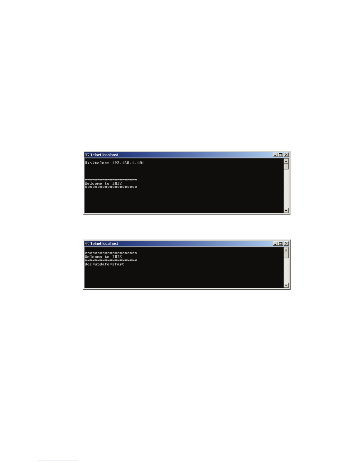
4. Enter telnet 192.168.1.101 and tap the return button.
The message „Welcome to IRIS“ is displayed
5. Enter doc*update=start and tap the return button.

13
TPI-8 / TPI-12 Touch Panel
Owner’s manual
The dialog Update Mode and a onscreen keyboard appears at the screen of
the TPI-8/TPI-12.
6. Click on the Network Connections button in the Update Mode dialog.
The window Network Connections appears.
7. Double click on Local Area Connection.
The window Local Area Connection Properties appears.
8. Click on button Properties in the Local Area Connection dialog.
14
TPI-8 / TPI-12 Touch Panel
Owner’s manual
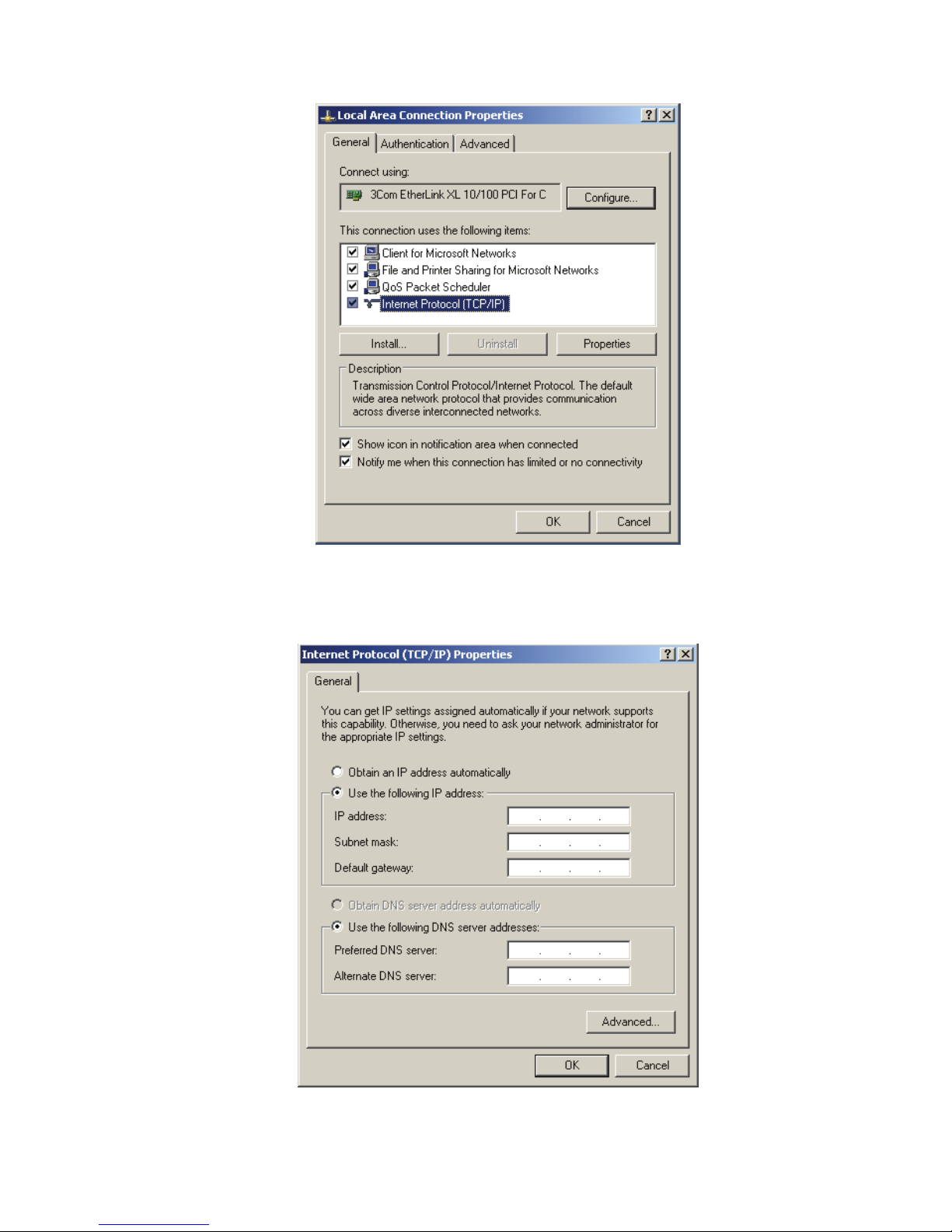
The pop-up window Local Area Connection Properties appears.
9. Double click on Internet Protocol (TCP/IP).
The pop-up window Internet Protocol (TCP/IP) Properties appears.

15
TPI-8 / TPI-12 Touch Panel
Owner’s manual
10. Choose the option Use the following IP address in the window.
11. Type the required IP address in the IP address input field.
12. Type the required subnet mask in the Subnet mask input field.
13. Type the required gateway in the Default gateway input field.
14. Close the window Internet Protocol (TCP/IP) Properties by clicking on
the OK button.
The network configuration of the TPI-8/TPI-12 is now complete.
15. Close the window Local Area Connection Properties by clicking on the
OK button.
16. Close the window Local Area Connection Status by clicking on the
Close button.
17. Close the window Network Connections.
Updating the IRIS-Net project file or application
The purpose of this procedure is to build a connection between a PC and a TPI8/TPI-12 with factory network settings (see page 11) and updating the IRIS-Net
project file or IRIS-Net application of the TPI-8/TPI-12. In the following it is
assumed that the file to be transfered is available at the PC.
1. Connect the network connection of your PC to the Ethernet interface
of the TPI-8/TPI-12 directly with a crossover cable, or with a patch
cable and a hub/switch.
2. Activate the power supply system of the TPI-8/TPI-12.
After some seconds a IRIS-Net project signals the successful start activity
of the TPI-8/TPI-12.
3. Click on Start > All Programs > Accessories > Command Prompt.
The window command prompt appears.
16
TPI-8 / TPI-12 Touch Panel
Owner’s manual
4. Enter telnet 192.168.1.101 and tap the return button.
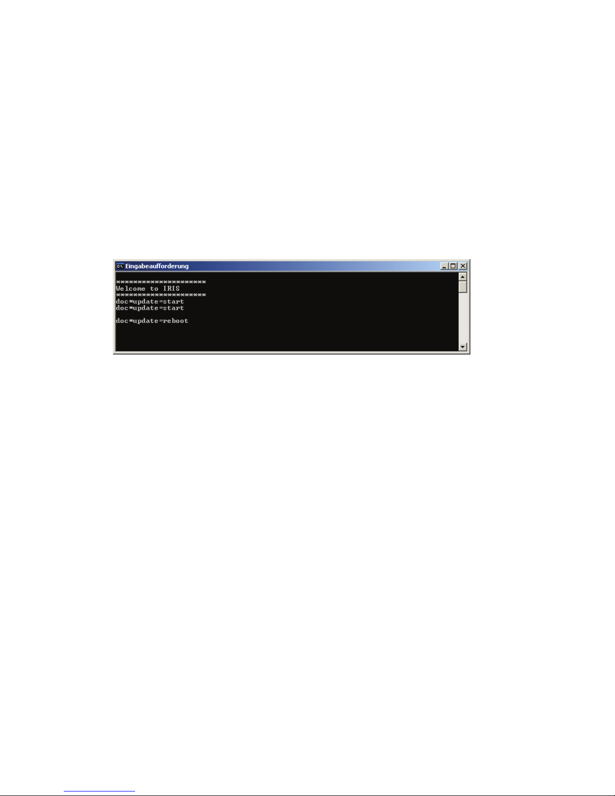
5. Enter doc*update=start and tap the return button.
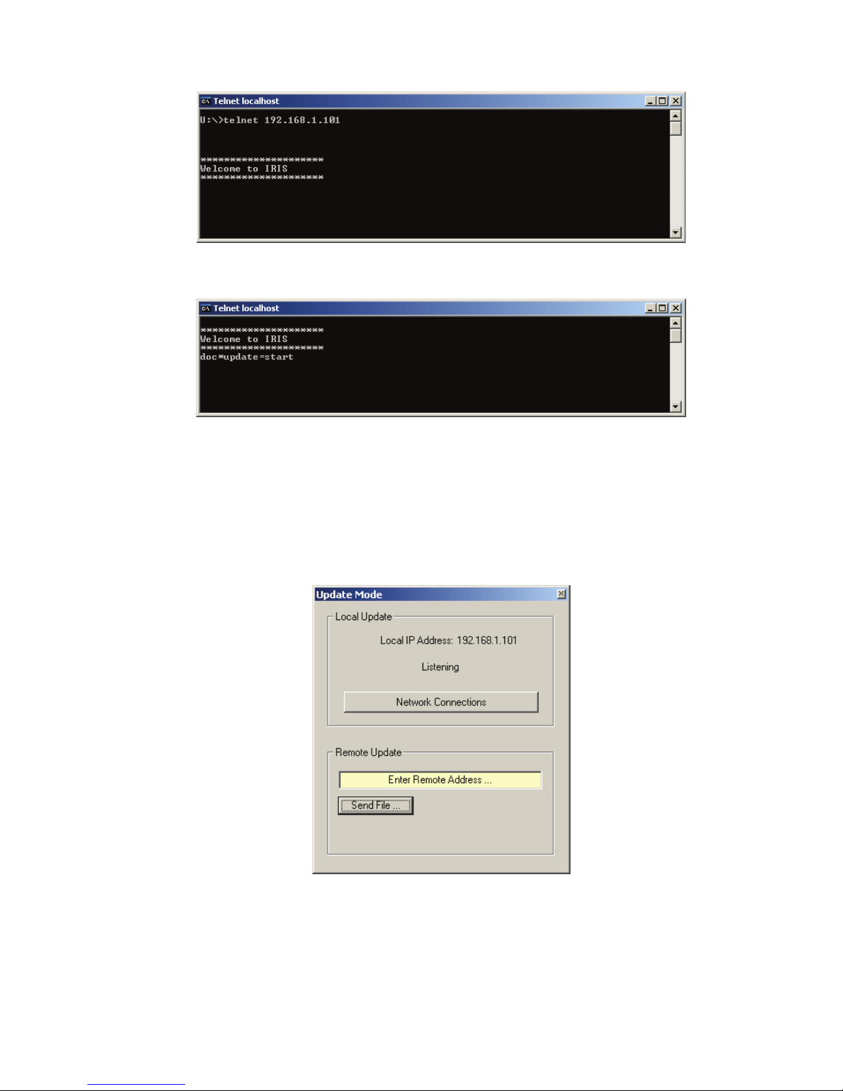
The dialog Update Mode and a onscreen keyboard appears at the screen of
the TPI-8/TPI-12. The TPI-8/TPI-12 is now ready-to-receive.
6. Start IRIS-Net application on your PC.
7. Click on Configuration > Update Touch Panel.
The dialog Update Mode appears.
8. Type 192.168.1.101 in the Enter Remote Address.. input field and tap
the return button.
17
TPI-8 / TPI-12 Touch Panel
Owner’s manual
9. Click on Send File ... button in the Update Mode dialog.
The window Open appears.
10. Select the file to be transfered in the window Open and click on the
Open button. The file types Project Files (*.ds) und Application
Archives (*.zip) can be selected.
The file is now sent to the TPI-8/TPI-12. The successfull transmission is
indicated by message „success“ in the Update Mode dialog at the PC and
also the TPI-8/TPI-12.
11. Enter doc*update=reboot and tap the return button.
The TPI-8/TPI-12 reboots and uses the new IRIS-Net project file or IRIS-Net
application.
Editing of screen saver and display backlight configuration
The purpose of this procedure is to edit the screen saver and display backlight
configuration of the TPI-8/TPI-12. In the following it is assumed that the TPI-8/
TPI-12 is activated and the IRIS-Net-project is shown in fullscreen mode.
1. Connect the network connection of your PC to the Ethernet interface
of the TPI-8/TPI-12 directly with a crossover cable, or with a patch
cable and a hub/switch.
2. Click on Start > All Programs > Accessories > Command Prompt.
The window command prompt appears.
18
TPI-8 / TPI-12 Touch Panel
Owner’s manual
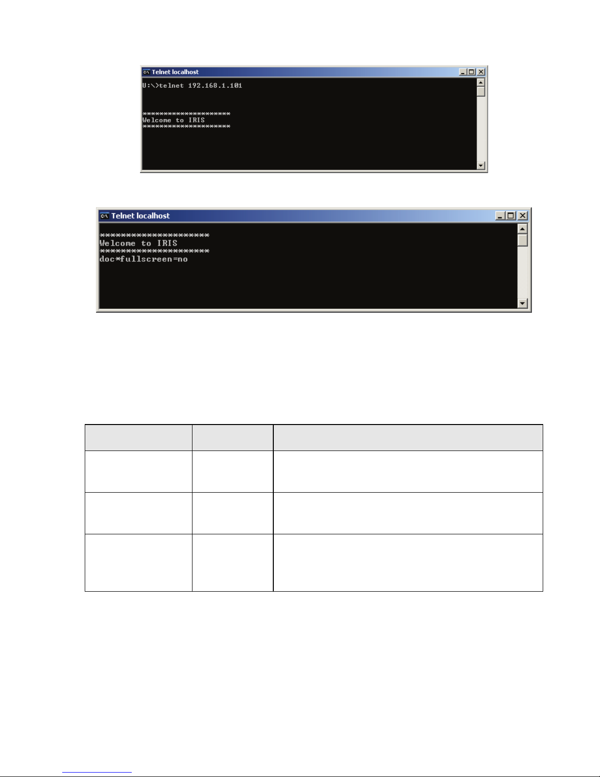
3. Enter telnet 192.168.1.101 and tap the return button.
4. Enter doc*fullscreen=no and tap the return button.
The IRIS-Net project shown at the TPI-8/TPI-12 leaves the fullscreen mode.
5. Click on Start > Settings > Control Panel > Display > Screen Saver at
the TPI-8/TPI-12.
The screensaver „Irisnetscreensaver“ is preselected, following table shows
the default settings of screensaver parameters.
6. Configure the screen saver and backlight according to your
requirements.
7. Close the dialogs Display Properties and Control Panel.
8. Enter doc*fullscreen=yes at the PC and tap the return button.
Parameter Value Description
Wait 25 minutes The screensaver is activated after 25 min-
utes.
Dim Screen to 25% The brigthness of the screen is reduced to
25% of maximum brightness.
Switch off
Backlight after
Activated,
25 minutes
The backlight of the screen is deactivated
when the screensaver was active for 25
minutes.

19
TPI-8 / TPI-12 Touch Panel
Owner’s manual
2.4 Maintenance & Care
TPI-8 and TPI-12 need only minimum maintenance and care. In case of light
contamination clean the unit with a clean, dry rag. To remove persistent dirt, use
a mild cleaning agent and a clean, soft, slightly dampened cloth only.
Replacing the Lithium Battery
The System’s main board houses a Lithium battery (CR-2032). If, in the touch
panel’s BIOS, the time is reset to the default value (SUN 01.JAN.2006), the
Lithium battery needs to be replaced.
In doing so, please proceed as follows:
1. Disconnect the touch panel from the power supply.
2. Remove the CompactFlash Card.
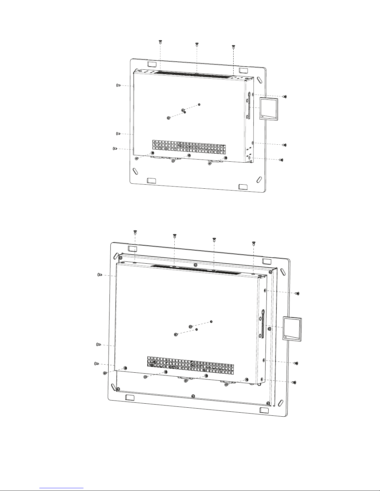
3. Open the unit by removing the screws as shown in the following
illustration.
NOTE:
Do not use any abrasives, abrasive sponges, steel wool or solvents like alcohol, acetone or petroleum ether for cleaning the
touch screen surface.
20
TPI-8 / TPI-12 Touch Panel
Owner’s manual
TPI-8:
TPI-12:

21
TPI-8 / TPI-12 Touch Panel
Owner’s manual
4. Remove the Lithium battery by pushing the ejection clip
outward.
5. Put a fresh Lithium battery into the battery base.
6. Mind the battery’s polarity (anode pointing to the top).
7. Replacing the Lithium battery is only permissible when using a
battery of the same type.
8. Close the unit.
Do not dispose the exhausted lithium battery in the domestic refuse. Dispose
the battery according to local regulations concerning the removal of special
refuse, (e.g. bring exhausted batteries to particular collecting points).

22
TPI-8 / TPI-12 Touch Panel
Owner’s manual
3 Appendix
3.1 Example of use
3.2 Troubleshootings
Using multiple Touch Panels at a Ethernet
If more than one Touch Panel is present on the Ethernet network, a warning
message may be shown on the TPI-8/TPI-12 during the boot up procedure. In
this case an individual „computer name“ must be assigned to each Touch Panel.
In the following it is assumed that the TPI-8/TPI-12 is activated and the IRISNet-project is shown in fullscreen mode.
1. Connect the network connection of your PC to the Ethernet interface
of the TPI-8/TPI-12, either directly with a CAT-5 crossover cable, or
through a hub/switch.
2. On your PC click on Start > All Programs > Accessories > Command
Prompt.
The command prompt dialog will appear.
Ethernet Switch
TPI-12
TPI-8
TPI-8
+24V DC
Control PC
with IRIS-Net Software

23
TPI-8 / TPI-12 Touch Panel
Owner’s manual
3. Enter telnet 192.168.1.101 and press the return key.
4. Enter doc*fullscreen=no and press the return key.
The IRIS-Net project shown on the TPI-8/TPI-12 will leave fullscreen mode.
5. On the TPI-8/TPI-12 click on Start > Settings > Control Panel > System.
The System Properties dialog box will appear.
6. Select the Computer Name tab.
7. Click on the Change... button.
The dialog box Computer Name Changes will appear. The default name
„SNREFERENZ“ is shown in the Computer name text box.
8. Type a new name for the Touch Panel in the text box.
9. Close the Computer Name Changes dialog by clicking on the OK
button.
A dialog „You must restart this computer for the changes to take effect“ will
appear, close this dialog by clicking on the OK button.
10. Close the System Properties dialog by clicking on the OK button.
The System Settings Change dialog will appear.
11. Click on the Yes button to reboot the Touch Panel.
 Loading...