

Page 1
GmbH • Hirschberger Ring 45 • 94315 Straubing • Telefon (09421) 706-0 • Telefax (09421) 706-265
Subject to change without prior notice. Printed in Germany Vs 02 10.03.2009 D367600 / F01U108146
Part Number
Technische Informationen
Engineering Data Sheet
Informations Techniques
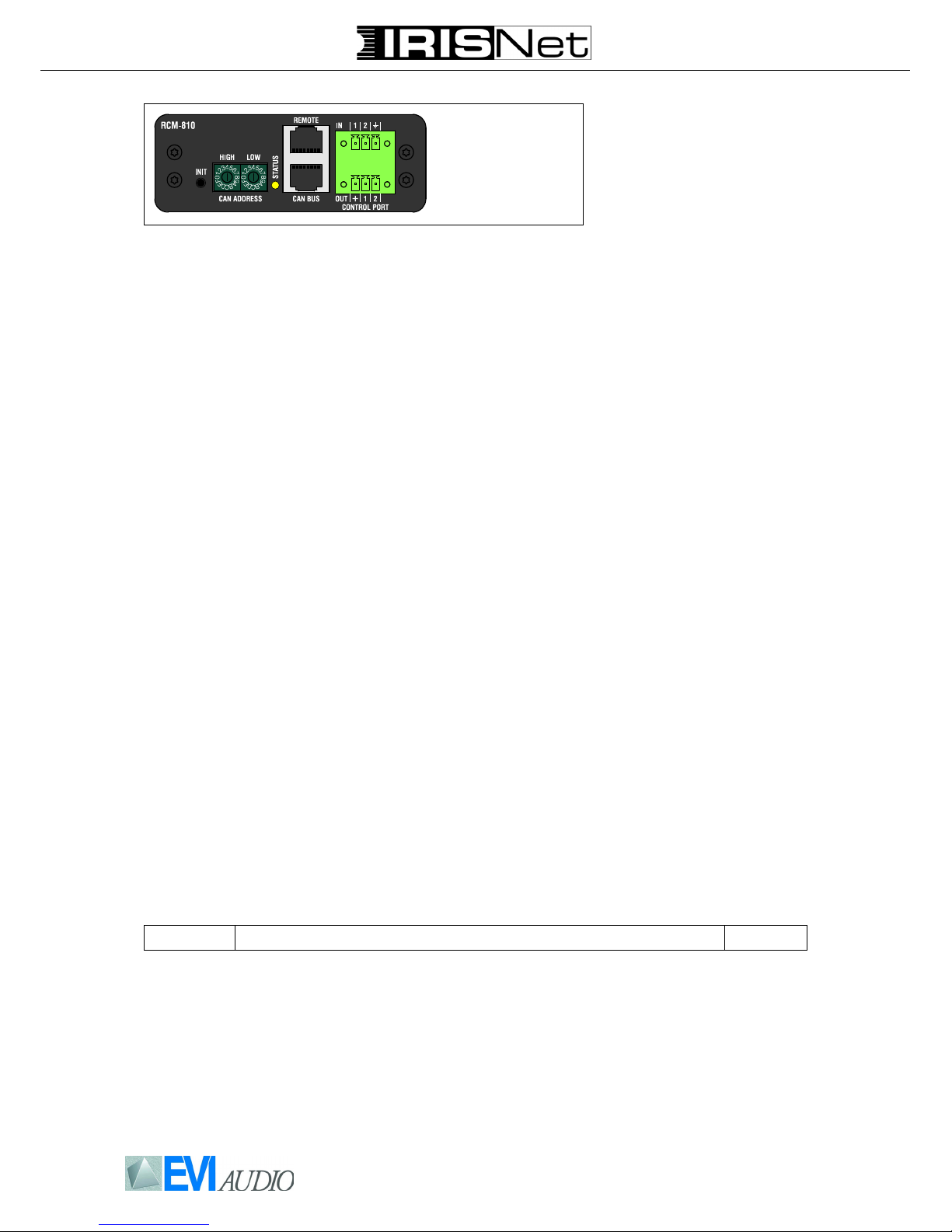
RCM-810
Remote Control Module
Beschreibung Description Description
Das Remote-Control-Modul RCM810 ist ein optionales Einbaumodul
zur Überwachung und Fernbedienung einer Endstufe über ein Remote-Control-Netzwerk.
An einem Remote-Netzwerk können maximal 100 Endstufen angeschlossen sein. IRIS-Net kann
mehrere Remote-Control-Netzwerke mit bis zu 250 Geräten verwalten. Neben der NetzwerkSchnittstelle stellt das RCM-810
zwei Steuereingänge und zwei
Steuerausgänge zur Verfügung.
The RCM-810 Remote Control
Module is an optional module for
supervision and remote control of
power amplifiers.
RCM-810 modules allow the amplifiers to be integrated into a remote
control network with up to 100
devices. Up to 250 amplifiers can
be used in an IRIS-Net project
when multiple networks are used.
Apart from the network port, the
RCM-810 also offers freely programmable control inputs and control outputs.
Le module de télécommande RCM810 est un module optionnel pour la
surveillance et la commande à distance d’amplificateurs de puissance.
Les modules RCM-810 permettent
d'intégrer les amplis dans un réseau
contrôlé à distance comprenant un
maximum de 100 membres. En utilisant des réseaux multiples à l'intérieur d'un projet IRIS-Net il est
possible d'utiliser un maximum de
250 amplis. En plus de son port
réseau, le RCM-810 propose également des entrées et des sorties de
contrôle entièrement programmables.
Weitere RCM-810 Eigenschaften:
• Steuerung/Konfiguration:
- Power ON/OFF
- Einschaltverzögerung
-Mute
- Steuerein- und ausgänge
• Überwachung/Anzeigen:
- Angeschlossene Last für jeden
Endstufen-Kanal
- Output VU
-Protect
- Limit
- Pilotton
- Temperatur
- Gain/Sensitivity
- Steuerein- und ausgänge
Alle Details hierzu finden Sie in den
Bedienungsanleitungen der Endstufen, in die das RCM-810 eingebaut wird.
Additional RCM-810 features:
• Control/Configuration:
- Power ON/OFF
- Power On Delay
-Mute
- Control Inputs/Outputs
• Supervision/Status indicators:
- Load supervision for each amplifier channel
- Output VU
-Protect
- Limit
- Pilot tone
- Temperature
- Gain/Sensitivity
- Control Inputs/Outputs
For further details please check the
owner’s manual of the amplifier
which the RCM-810 will be used in.
Autres caractéristique du RCM-810:
• Contrôle/Configuration:
- Interrupteur Marche/Arrêt
- Temporisation à la mise sous tension
-Mute
- Entrées/sorties de contrôle
• Témoin de Surveillance et d’État:
- Surveillance de la charge de chaque canal de l’ampli
- VU-mètre du niveau de sortie
- Témoin Protect
- Témoin Limit
- Tonalité Pilote
- Température
- Gain/Sensibilité
- Entrées/sorties de contrôle
Pour les détails veuillez vous reporter au mode d’emploi de l’amplificateur, auquel le RCM-810 est
associé.
RCM-810 Remote Control Module D 170 446
Inhalt Contents Contenu
1 x Technische Informationen RCM-810
1 x RCM-810
2 x Stecker 3-pol.
Phoenix MC1,5/3-STF-3,81 (Nr.1827716)
1 x Verbindungskabel (34-polig, 60 mm)
2 x Schrauben Kombi-Torx M3x10
1 x Engineering Data Sheet RCM-810
1 x RCM-810
2 x Connector 3-pole
Phoenix MC 1,5/3-STF-3,81 (Nr.1827716)
1 x Ribbon Cable (34-pole, 60 mm)
2 x M3x10 Combination Torx Screws
1 x Informations techniques RCM-810
1 x RCM-810
2 x Connecteurs 3-pôles
Phoenix MC 1,5/3-STF-3,81 (Nr.1827716)
1 x Cordon d’interconnexion interne
(34-pôles, 60 mm)
2 x Vis Combination Torx M3x10
Page 2
GmbH • Hirschberger Ring 45 • 94315 Straubing • Telefon (09421) 706-0 • Telefax (09421) 706-265
Subject to change without prior notice. Printed in Germany Vs 02 10.03.2009 D367600 / F01U108146
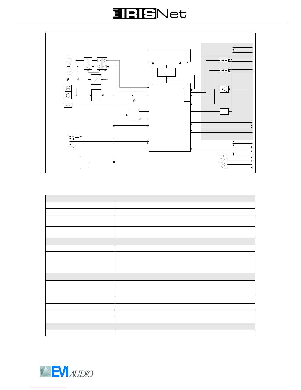
Technical Specifications
RCM-810 Block Diagram
NETWORK AND GENERAL FEATURES
Remote Control and Software IRIS-Net, Multiple PCs possible, MS Windows 2000, XP, Vista
Maximum Configuration 250 Amplifiers in total, 100 Amplifiers per CAN bus, 1000 meter cable run
Amplifier Supervision Operation mode, temperature, output voltage and current, impedance of
connected speakers, protection mode status, pilot tone detection
Network Supervision CAN bus failures, defective or missing amplifiers, bandwidth, failure protocol
and messaging
INTERFACES
CAN 10…500 kbaud, 2 x RJ-45 (IRIS-Net Control)
GPIO Control Port 2 x 3-pole Euro block
2 Control Inputs
2 Control Outputs
2 Reference Outputs (+5 V, 200 mA / GND)
RCM-810 GENERAL SPECIFICATIONS
Supply Voltage/Current +5 V DC / 320 mA
+15 V DC / 80 mA
-15 V DC / 80 mA
Power Consumption 4 W
Operating Temperatur Range 0 °C...40 °C
Dimensions (W x H x D) 103.5 x 37 x 103 mm
Weight 115 g
ACCESSORIES
3-pole Euro block connector For GPIO Control Port
Controller
SRAM
Latch
CAN
CAN-LED
FRAM
/ATMEL_PROG
/RCM_EN
RCM_CLK
RCM_MOSI
RCM_MISO
/RCM_DETECT
REMOTE
CAN BUS
Galvanic Isolation
P/S
DC
DC
CAN
ADDRESS
+5V
CAN-LED
0
2
1
3
4
5
6
7
8
9
A
B
C
D
E
F
0
2
1
3
4
5
6
7
8
9
A
B
C
D
E
F
CONTROL
PORT
+5V
DGND
+5V
Reset
Watchdog
+5V
Test
AMP ID
POWER ON
MUTE A / B
STANDBY
LIMIT /
PROTECT /
REDUCTION
CURRENT A- / B-
CURRENT A+ / B+
VOLTAGE A- / B-
VOLTAGE A+ / B+
AGND
+15V
-15V
U-TEMP
ADC
Only 2 Channel AMP
IrisNet LED
+15V
AGND
-15V
TEMP_Board
BRIDGED
POWER_GOOD
Pilot Tone
Detection
INIT
Page 3

GmbH • Hirschberger Ring 45 • 94315 Straubing • Telefon (09421) 706-0 • Telefax (09421) 706-265
Subject to change without prior notice. Printed in Germany Vs 02 10.03.2009 D367600 / F01U108146
CAUTION: These installation instructions are for use by qualified service personnel only. To reduce the risk of electric shock do
not perform any servicing other than that contained in the owners manual unless you are qualified to do so.
Montage in Mehrkanal-Endstufe Installation (multi channel amp) Installation (multi channel amp)
1. Endstufe ausschalten und Netzstekker abziehen
2. Entfernen Sie die 4 Schrauben n des
Endstufen-Bodens
3. Lösen Sie den Boden wie abgebildet
o und ziehen Sie ihn nach vorne weg
4. Leerblende an Rückwand der Endstufe abschrauben (2 Schrauben)
5. Fixierung des 16-poligen Flachbandkabels durch Kabelbinder p lösen
(siehe Abbildung)
6. RCM-810-Modul in Slot einschieben
7. Kabelverbindung mit RCM-810 herstellen: 16-poliges Flachbandkabel in
CN3 auf RCM-810 Modul einstecken
8. Modul unter Verwendung der seitlichen Führung q horizontal ausrichten
(siehe Abbildung) und mit 2 Schrauben an Rückwand befestigen
9. Endstufen-Boden aufschrauben (das
Flachbandkabel darf nicht beschädigt/
eingeklemmt werden)
10. CAN-Adresse des Moduls über
ADDRESS-Wahlschalter einstellen
11. Anschließen benötigter Schnittstellen
(CAN, Control-Port)
12. Netzkabel in Endstufe einste-cken
und Endstufe einschalten, das Modul
wird automatisch erkannt
1. Switch off the power to the amplifier
and disconnect the mains lead
2. Remove the 4 screws n from the bottom cover of the amplifier.
3. Loosen the bottom cover as shown o
and remove it by pulling it out towards
the front panel
4. Remove the cover panel from the rear
panel (2 screws)
5. Release the 16-pole ribbon cable by
cutting the tie wrap p (see illustration
below)
6. Insert the RCM-810 module into the
slot
7. Plug the 16-pole ribbon cable into the
connector labelled CN3 on the RCM810 module
8. Slide the module into place locating it
into the guide slot q on side of the
chassis and secure it in place using
the 2 screws
9. Refit the bottom cover making sure
the ribbon cable will not be damaged
10. Set the module’s CAN address using
the ADDRESS selector switches
11. Connect the interfaces required (CAN,
Control Port)
12. Reconnect the mains lead and switch
the amplifier on, the RCM-810 is automatically detected and is now ready
for use.
1. Éteignez l’ampli de puissance et
débranchez-le du secteur
2. Retirer les 4 vis n de la plaque située
à l‘arrière de l‘ampli.
3. Retirer la plaque comme indiqué o
en la tirant vers soi.
4. Enlevez le panneau arrière (2 vis)
5. Détachez le câble 16 points en coupant le lien p (voir illustration ci-dessous)
6. Insérez le module RCM-810 dans
l'emplacement
7. Branchez le câble 16 points en CN3
sur le module RCM-810
8. Insérez le module horizontalement en
utilisant le guide q situé sur le côté
du châssis et bloquez-le en utilisant
les 2 vis (voir illustration ci-dessous)
9. Remettez en place le fond de l’amplificateur, le cordon d interconnexion ne
doit pas être écrasé
10. Réglez l’adresse CAN du module à
l’aide des switches du sélecteur
ADDRESS
11. Connectez les interfaces adéquates
(CAN, Port de Contrôle)
12. Rebranchez le cordon secteur et mettez sous tension l’amplificateur de
puissance, le module RCM-810 est
automatiquement reconnu par l’amplificateur
Page 4

GmbH • Hirschberger Ring 45 • 94315 Straubing • Telefon (09421) 706-0 • Telefax (09421) 706-265
Subject to change without prior notice. Printed in Germany Vs 02 10.03.2009 D367600 / F01U108146
CAUTION: These installation instructions are for use by qualified service personnel only. To reduce the risk of electric shock do
not perform any servicing other than that contained in the owners manual unless you are qualified to do so..
Abmessungen / Dimensions
Montage in 2-Kanal-Endstufe Installation (2 channel amp) Installation (ampli à 2 voies)
1. Endstufe ausschalten und Netzstekker abziehen
2. Entfernen Sie die 4 Schrauben n des
Endstufen-Deckels
3. Lösen Sie den Deckel wie abgebildet
o und ziehen Sie ihn nach vorne
weg.
4. Leerblende an Rückwand der Endstufe abschrauben (2 Schrauben)
5. RCM-810-Modul in Slot einschieben
und mit 2 Schrauben an Rückwand
befestigen
6. Kabelverbindung mit 34-poligem
Flachbandkabel herstellen: CN4 auf
RCM-810 Modul mit CN3 auf Endstufenboard
7. Endstufen-Deckel aufschrauben
8. CAN-Adresse am Modul über
ADDRESS-Schalter einstellen
9. Anschließen benötigter Schnittstellen
(CAN, Control-Port)
10. Netzkabel in Endstufe einstecken und
Endstufe einschalten, das Modul wird
automatisch erkannt
1. Switch off the power to the amplifier
and remove the mains lead.
2. Remove the 4 screws n from the top
cover of the amplifier.
3. Loosen the top cover as shown o
and remove it by pulling it out towards
the front panel
4. Remove the cover panel from the rear
panel (2 screws)
5. Slide the RCM-810 module into the
slot and secure in in place using the 2
screws (see illustration below)
6. Gently push the 60 mm ribbon cable
into the connector labelled CN4 on the
RCM-810 and the connector labelled
CN3 on the amplifier main board.
7. Refit the top cover
8. Set the module’s CAN address using
the ADDRESS selector switches
9. Connect the interfaces required (CAN,
Control Port)
10. Reconnect the mains lead and switch
the amplifier on, the RCM-810 is automatically detected and is now ready
for use.
1. Éteignez l’ampli de puissance et débranchez-le du secteur
2. Retirer les 4 vis n du capot supérieur de
l‘ampli.
3. Retirer le capot comme indiqué o en le
tirant vers soi.
4. Enlevez le panneau arrière (2 vis)
5. Insérez le module RCM-810 dans le slot et
verrouillez-le en place sur le panneau
arrière à l’aide des 2 vis (voir illustration cidessous)
6. Faites les branchements suivants à l’aide
du cordon d interconnexion de 60 mm :
CN4 du module RCM-810 relié à CN3 de la
carte-mère de l’amplificateur
7. Remettez en place le dessus de l’amplificateur
8. Réglez l’adresse CAN du module à l’aide
des switches du sélecteur ADDRESS
9. Connectez les interfaces adéquates (CAN,
Port de Contrôle)
10. Rebranchez le cordon secteur et mettez
sous tension l’amplificateur de puissance,
le module RCM-810 est automatiquement
reconnu par l’amplificateur.
 Loading...