

IRIS Net RCM-26 Owner's Manual
OWNER’S MANUAL
BEDIENUNGSANLEITUNG
MODE D’EMPLOI
RCM-26
Remote Control Module

2
RCM-26 Remote Control Module
CONTENTS
Introduction . . . . . . . . . . . . . . . . . . . . . . . . . . . . . . . . . . . . . . . . . . . . . . . . . 6
System Description . . . . . . . . . . . . . . . . . . . . . . . . . . . . . . . . . . . . . . . 6
Unpacking and Warranty . . . . . . . . . . . . . . . . . . . . . . . . . . . . . . . . . . . 7
Installation Notes . . . . . . . . . . . . . . . . . . . . . . . . . . . . . . . . . . . . . . . . . 8
Installation. . . . . . . . . . . . . . . . . . . . . . . . . . . . . . . . . . . . . . . . . . . . . . . 8
Conversion from Pre Fader Mode to Post Fader Mode . . . . . . . . . . . . 8
IRIS-Net . . . . . . . . . . . . . . . . . . . . . . . . . . . . . . . . . . . . . . . . . . . . . . . . 9
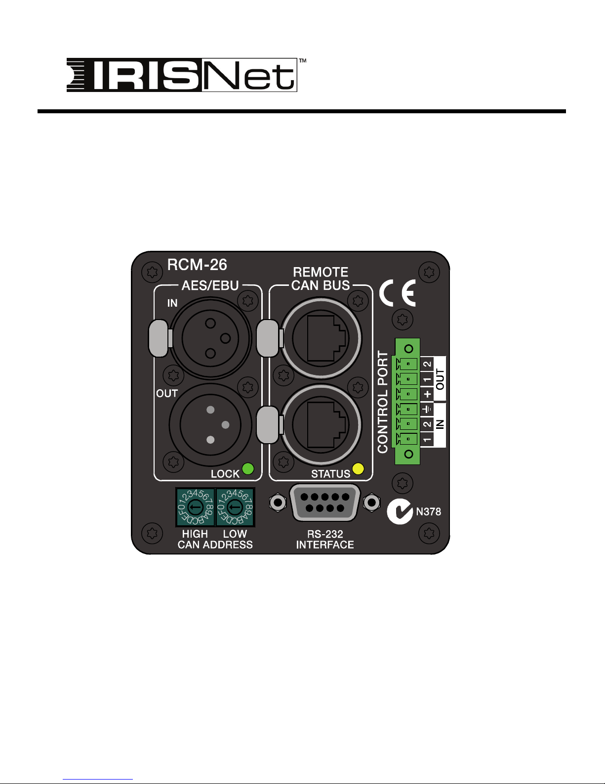
Controls and Connections . . . . . . . . . . . . . . . . . . . . . . . . . . . . . . . . . . . . . 11
1, AES/EBU-IN. . . . . . . . . . . . . . . . . . . . . . . . . . . . . . . . . . . . . . . . . . . 11
2, AES/EBU-OUT. . . . . . . . . . . . . . . . . . . . . . . . . . . . . . . . . . . . . . . . . 12
3, LOCK-LED . . . . . . . . . . . . . . . . . . . . . . . . . . . . . . . . . . . . . . . . . . . . 12
4, REMOTE CAN BUS Connection . . . . . . . . . . . . . . . . . . . . . . . . . . . 12
5, STATUS LED. . . . . . . . . . . . . . . . . . . . . . . . . . . . . . . . . . . . . . . . . . 14
6, ADDRESS Selector Switch . . . . . . . . . . . . . . . . . . . . . . . . . . . . . . . 14
7, CONTROL PORT . . . . . . . . . . . . . . . . . . . . . . . . . . . . . . . . . . . . . . 16
8, RS-232 Interface . . . . . . . . . . . . . . . . . . . . . . . . . . . . . . . . . . . . . . . 16
CAN Bus Principles . . . . . . . . . . . . . . . . . . . . . . . . . . . . . . . . . . . . . . . . . . . 18
System Examples . . . . . . . . . . . . . . . . . . . . . . . . . . . . . . . . . . . . . . . . 19
Performance Specifications . . . . . . . . . . . . . . . . . . . . . . . . . . . . . . . . . 20
INHALT
Einleitung . . . . . . . . . . . . . . . . . . . . . . . . . . . . . . . . . . . . . . . . . . . . . . . . . . . 27
Systembeschreibung . . . . . . . . . . . . . . . . . . . . . . . . . . . . . . . . . . . . . . 27
Auspacken & Garantie . . . . . . . . . . . . . . . . . . . . . . . . . . . . . . . . . . . . . 28
Installationshinweise . . . . . . . . . . . . . . . . . . . . . . . . . . . . . . . . . . . . . . 29
Einbau. . . . . . . . . . . . . . . . . . . . . . . . . . . . . . . . . . . . . . . . . . . . . . . . . . 29
Umbau von Pre-Fader- auf Post-Fader-Betriebsart . . . . . . . . . . . . . . . 29
IRIS-Net . . . . . . . . . . . . . . . . . . . . . . . . . . . . . . . . . . . . . . . . . . . . . . . . 30
Bedienelemente und Anschlüsse . . . . . . . . . . . . . . . . . . . . . . . . . . . . . . . . 32
1, AES/EBU-IN. . . . . . . . . . . . . . . . . . . . . . . . . . . . . . . . . . . . . . . . . . . 32
2, AES/EBU-OUT. . . . . . . . . . . . . . . . . . . . . . . . . . . . . . . . . . . . . . . . . 33
3, LOCK-LED . . . . . . . . . . . . . . . . . . . . . . . . . . . . . . . . . . . . . . . . . . . . 33
4, REMOTE CAN BUS-Anschlüsse . . . . . . . . . . . . . . . . . . . . . . . . . . . 33
5, STATUS LED. . . . . . . . . . . . . . . . . . . . . . . . . . . . . . . . . . . . . . . . . . 35
6, ADDRESS-Wahlschalter . . . . . . . . . . . . . . . . . . . . . . . . . . . . . . . . . 35
7, CONTROL PORT . . . . . . . . . . . . . . . . . . . . . . . . . . . . . . . . . . . . . . 37
8, RS-232-Schnittstelle . . . . . . . . . . . . . . . . . . . . . . . . . . . . . . . . . . . . 37
Remote-Control-Netzwerk . . . . . . . . . . . . . . . . . . . . . . . . . . . . . . . . . . . . . . 39
Systembeispiele . . . . . . . . . . . . . . . . . . . . . . . . . . . . . . . . . . . . . . . . . . 41
Leitungsspezifikation . . . . . . . . . . . . . . . . . . . . . . . . . . . . . . . . . . . . . . 42

3
RCM-26 Remote Control Module
MATIÈRES
Introduction . . . . . . . . . . . . . . . . . . . . . . . . . . . . . . . . . . . . . . . . . . . . . . . . . 49
Description du système . . . . . . . . . . . . . . . . . . . . . . . . . . . . . . . . . . . . 49
Déballage et garantie . . . . . . . . . . . . . . . . . . . . . . . . . . . . . . . . . . . . . . 50
Remarques sur l’installation . . . . . . . . . . . . . . . . . . . . . . . . . . . . . . . . . 51
Conversion du mode pré-atténuateur au mode post-atténuateur . . . . . 51
IRIS-Net . . . . . . . . . . . . . . . . . . . . . . . . . . . . . . . . . . . . . . . . . . . . . . . . 52
Commandes et connexions . . . . . . . . . . . . . . . . . . . . . . . . . . . . . . . . . . . . . 54
1, AES/EBU-IN. . . . . . . . . . . . . . . . . . . . . . . . . . . . . . . . . . . . . . . . . . . 54
2, AES/EBU-OUT. . . . . . . . . . . . . . . . . . . . . . . . . . . . . . . . . . . . . . . . . 55
3, Témoin LOCK . . . . . . . . . . . . . . . . . . . . . . . . . . . . . . . . . . . . . . . . . 56
4, Connexion REMOTE CAN BUS. . . . . . . . . . . . . . . . . . . . . . . . . . . . 56
5, Témoin STATUS . . . . . . . . . . . . . . . . . . . . . . . . . . . . . . . . . . . . . . . 58
6, Sélecteurs ADDRESS . . . . . . . . . . . . . . . . . . . . . . . . . . . . . . . . . . . 58
7, PORT DE CONTROLE . . . . . . . . . . . . . . . . . . . . . . . . . . . . . . . . . . 60
8, Interface RS-232 . . . . . . . . . . . . . . . . . . . . . . . . . . . . . . . . . . . . . . . 60
Principes du Bus CAN . . . . . . . . . . . . . . . . . . . . . . . . . . . . . . . . . . . . . . . . . 62
Exemples de systèmes . . . . . . . . . . . . . . . . . . . . . . . . . . . . . . . . . . . . 64
Caractéristiques des Performances . . . . . . . . . . . . . . . . . . . . . . . . . . . 65
Appendix . . . . . . . . . . . . . . . . . . . . . . . . . . . . . . . . . . . . . . . . . . . . . . . . . . . . 68
Specifications/Technische Daten . . . . . . . . . . . . . . . . . . . . . . . . . . . . . 68
Block Diagram / Blockschaltbild . . . . . . . . . . . . . . . . . . . . . . . . . . . . . . 71
Dimensions / Abmessungen . . . . . . . . . . . . . . . . . . . . . . . . . . . . . . . . 72
4
RCM-26 Remote Control Module
Owner’s Manual
IMPORTANT SAFETY INSTRUCTIONS
1. Read these instructions.
2. Keep these instructions.
3. Heed all warnings.
4. Follow all instructions.
5. Do not use this apparatus near water.
6. Clean only with a dry cloth.
7. Do not block any ventilation openings. Install in accordance with the manufacture’s instructions.
8. Do not install near heat sources such as radiators, heat registers, stoves, or other apparatus (including
amplifiers) that produce heat.
9. Do not defeat the safety purpose of the polarized or the grounding-type plug. A polarized plug has two
blades with one wider than the other. A grounding type plug has two blades and a third grounding
prong. The wide blade or the third prong are provided for your safety. If the provided plug does not fit
into your outlet, consult an electrician for replacement of the obsolete outlet.
10. Protect the power cord from being walked on or pinched particularly at plugs, convenience
receptacles, and the point where they exit from the apparatus.
11. Only use attachments/accessories specified by the manufacturer.
12. Use only with the cart, stand, tripod, bracket, or table specified by the manufacturer, or sold with the
apparatus. When a cart is used, use caution when moving the cart/apparatus combination to avoid
injury from tip-over.
13. Unplug this apparatus during lightning storms or when unused for a long period of time.
14. Refer all servicing to qualified service personnel. Servicing is required when the apparatus has been
damaged in any way, such as power-supply cord or plug is damaged, liquid has been spilled or objects
have fallen into the apparatus, the apparatus has been exposed to rain or moisture, does not operate
normally, or has been dropped.
15. Do not expose this equipment to dripping or splashing and ensure that no objects filled with liquids,
such as vases, are placed on the equipment.
16. To completely disconnect this equipment from the AC Mains, disconnect the power supply cord plug
from the AC receptacle
17. The mains plug of the power supply cord shall remain readily operable.
The lightning flash with arrowhead symbol, within an equilateral triangle is intended to alert the user to the presence of uninsulated
“dangerous voltage“ within the product’s enclosure that may be of
sufficent magnitude to constitute a risk of electric shock to persons.
The exclamation point within an equilateral triangle is intended to
alert the user to the presence of important operating and maintenance (servicing) instructions in the literature accompanying the
appliance.
5
RCM-26 Remote Control Module
Owner’s Manual
IMPORTANT SERVICE INSTRUCTIONS
CAUTION:
These servicing instructions are for use by qualified personnel only. To reduce the risk of
electric shock, do not perform any servicing other than that contained in the Operating
Instructions unless you are qualified to do so. Refer all servicing to qualified service
personnel.
1. Security regulations as stated in the EN 60065 (VDE 0860 / IEC 65) and the CSA E65 - 94 have to be
obeyed when servicing the appliance.
2. Use of a mains separator transformer is mandatory during maintenance while the appliance is opened,
needs to be operated and is connected to the mains.
3. Switch off the power before retrofitting any extensions, changing the mains voltage or the output
voltage.
4. The minimum distance between parts carrying mains voltage and any accessible metal piece (metal
enclosure), respectively between the mains poles has to be 3 mm and needs to be minded at all times.
The minimum distance between parts carrying mains voltage and any switches or breakers that are
not connected to the mains (secondary parts) has to be 6 mm and needs to be minded at all times.
5. Replacing special components that are marked in the circuit diagram using the security symbol (Note)
is only permissible when using original parts.
6. Altering the circuitry without prior consent or advice is not legitimate.
7. Any work security regulations that are applicable at the locations where the appliance is being
serviced have to be strictly obeyed. This applies also to any regulations about the work place itself.
8. All instructions concerning the handling of MOS-circuits have to be observed.
NOTE:
SAFETY COMPONENT (MUST BE REPLACED BY
ORIGINAL PART)
Management of WEEE (waste electrical and electronic equipment) (applicable in
Member States of the European Union and other European countries with individual national policies on the management of WEEE) The symbol on the product or
on its packaging indicates that this product may not be treated as regular household waste, but has to be disposed through returning it at a Telex dealer.

6
RCM-26 Remote Control Module
Owner’s Manual
1 Introduction
1.1 System Description
The RCM-26 Remote Control Module is a two-channel digital controller module
for live sound reinforcement, PA and fixed installation applications. The module
can be used in a variety of Electro-Voice® and Dynacord® amps. Installing the
RCM-26 turns a conventional amp into a remote amplifier, which, at any time,
provides complete overview of the overall system status and control of all
system parameters.
RCM-26 modules allow the integration of amplifiers into a remote control
network with up to 250 units. This offers the possibility to control and monitor an
entire PA system from one or more PCs using the IRIS-Net™ - Intelligent
Remote & Integrated Supervision - software package. All operational states,
e.g. power-on status, temperature, modulation, limiting, activation of
protections, deviation from the load impedance, etc., are centrally registered
and displayed in IRIS-Net™. This provides the possibility to react and to
selectively intervene even before critical operational states arise. Programming
an automatic reaction, when specific thresholds are being exceeded or fallen
below, is also possible.
With an RCM-26 installed, the integrated impedance testing function allows very
precise monitoring of the connected loudspeaker systems. The impedance
testing function utilizes the internal test tone signal generator and voltage/
current measuring to determine the impedance of the loudspeaker systems
including crossovers and cables over the entire frequency range. IRIS-Net™
plots an impedance curve of the measured impedance that can be compared
with a formerly stored reference curve at any time. This reveals even smallest
loudspeaker defects or deficiencies instantly.
All parameters, like power on/off, level, muting, filters, etc. can be controlled in
real-time and stored in the amplifier. Besides controlling and monitoring
amplifiers, the RCM-26 also offers all conventional signal processing functions,
like parametric equalizers, frequency crossovers, delays, compressors and
limiters. Beyond that, linear-phase FIR-filters, zero-latency FIR-filters and digital
speaker protection algorithms are available to optimize the amplifiers and
loudspeaker system. All DSP-settings can be freely edited and stored in user
presets directly on the module. In the event of network failure or loss of power,

7
RCM-26 Remote Control Module
Owner’s Manual
all settings (filters, delay, level, etc.) stay intact, independent of the control by
the network.
Furthermore, the RCM-26 provides a control port with freely programmable
control inputs and control outputs. Control inputs (GPI's) allow the connection of
switches. IRIS-Net™ offers the possibility to program a variety of logic functions
for the inputs (e.g. switching to an alarm-preset with maximum energy in the
speech area). Control outputs (GPO's) allow the connection of external
components, which, for example, are used to signal specific states to peripheral
equipment. Consequently, an amplifier with a RCM-26 module installed
corresponds to highest safety requirements.
The RCM-26 has been designed with uncompromising audio quality in mind.
Analog audio inputs (internally) and an AES3 (AES/EBU) digital audio input with
XLR-type connector are provided. The use of the digital audio input offers a
dynamic range of 128 dB. Using the analog audio input offers a dynamic range
of 120 dB, which, by the way, is an absolute peak value for digital audio devices.
For further details about configuration, control and monitoring of amps with
installed RCM-26 modules, please refer to the documentation of the IRIS-Net™
software.
1.2 Unpacking and Warranty
Carefully open the packaging and take out the RCM-26 module. In addition to
this owner’s manual the package also includes
• the module itself,
• a warranty certificate and
• a 6-pole screwlock connector (for the control port).
Make sure that the warranty certificate is correctly filled in, for only a completed
warranty card entitles you to file any possible claims. Keep the original invoice
that states the purchase/delivery date together with the warranty certificate at a
safe place.
The warranty period for the module is 36 months, starting from the date when
receiving the product from the dealer.
8
RCM-26 Remote Control Module
Owner’s Manual
1.3 Installation Notes
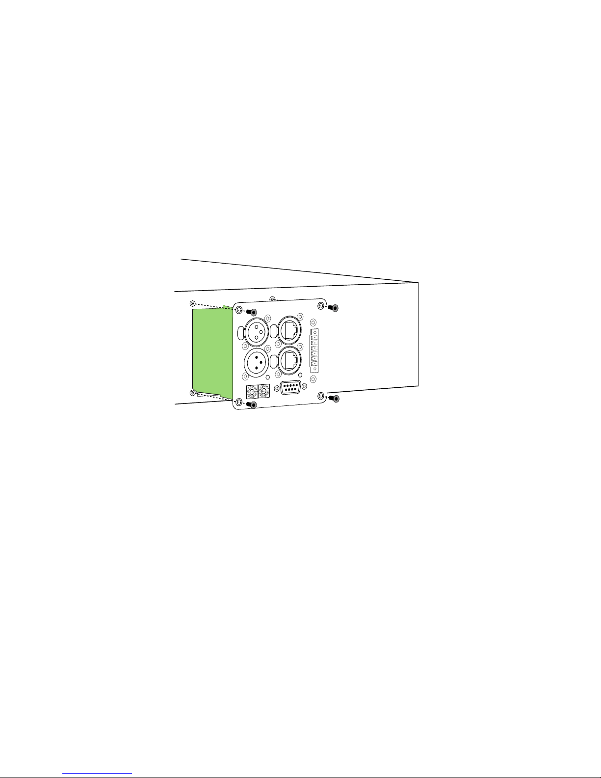
Installation
1. Switch the power amp’s power off and pull the mains plug
2. Remove the cover panel from the rear panel (4 screws)
3. Insert the RCM-26 module in the slot and lock it in place on the rear panel
using the 4 screws (see illustration 1.1)
4. Set the module’s CAN-address using the ADDRESS selector switches
5. Connect the needed interfaces (CAN, Audio, Control Port, RS-232)
6. Reconnect the mains cord and switch on the power amplifier
7. The power amp automatically recognizes the installed RCM-26 module
Conversion from Pre Fader Mode to Post Fader Mode
The RCM-26 is shipped from the factory in the recommended "Pre Fader"
mode, so the input level controllers on the front of the amplifier are taken out of
operation by installation of the RCM-26. If the input level controller are to be
usable with a RCM-26 installed, the RCM-26 must be converted to "Post Fader"
mode.
Illustration 1.1: Installation of a RCM-26
9
RCM-26 Remote Control Module
Owner’s Manual
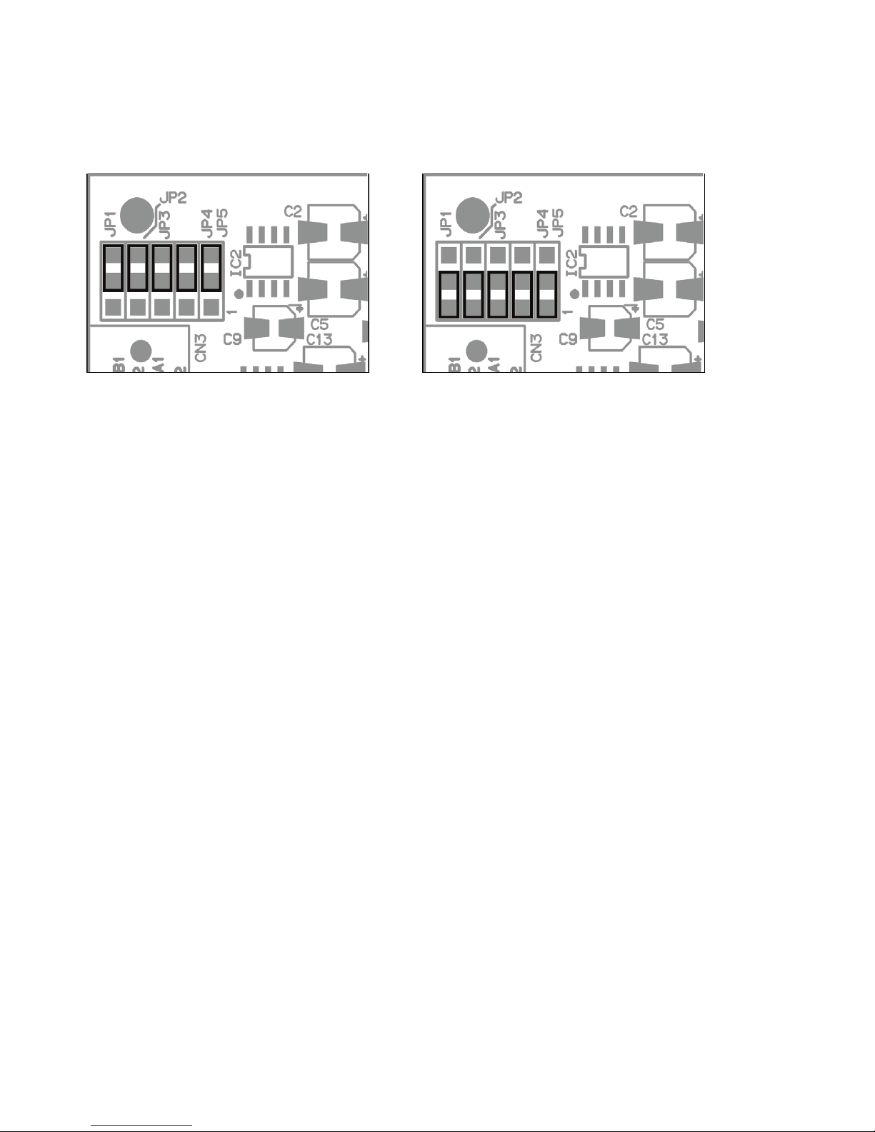
The conversion is done by changing the jumper settings of jumper JP1 to JP5
on the RCM-26. The following pictures show the jumper settings for "Pre Fader"
mode and "Post Fader" mode. Only the jumper settings shown are allowed.
Note:
On RCM-26 Remote Control Modules built in 2006 there are no jumpers at JP1
to JP5, instead the conversion has to be done via „cut&solder“. This means:
1. The strip conducter of the top and middle contact of each JP1 to JP5 has to
be cut.
2. A link has to be soldered between the middle and lower contact of each JP1
to JP5.
1.4 IRIS-Net
Configuring and controlling a remote amplifier with a RCM-26 module installed
is possible through the use of IRIS-Net™ (Intelligent Remote & Integrated
Supervision) PC-software. IRIS-Net™ allows programming the RCM-26
module’s complete configuration while the computer is off-line. All instructions
on how to configure, operate and monitor all RCM-26 functions are included in
the IRIS-Net™ help files.
Illustration 1.2: Pre Fader mode (left) and Post Fader mode (right)
10
RCM-26 Remote Control Module
Owner’s Manual
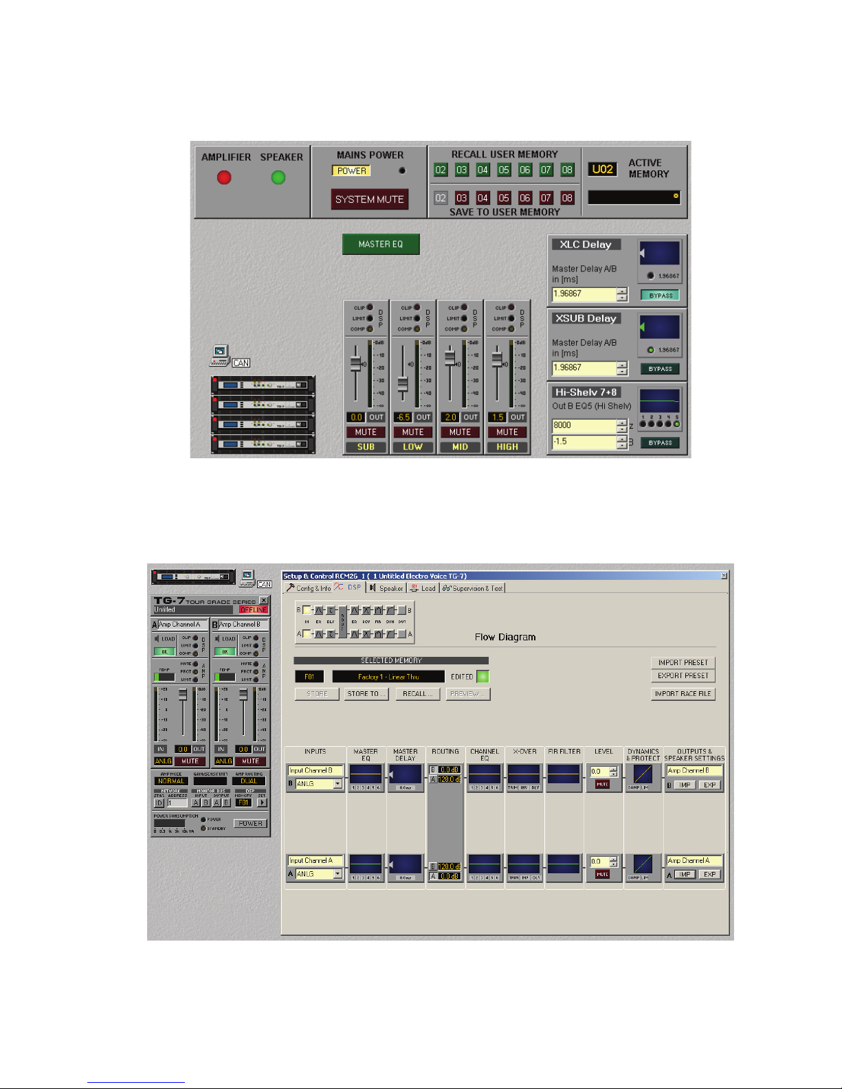
The following illustrations show an example of a power amplifier system in IRISNet™ and the DSP flow chart of a RCM-26
Illustration 1.3: Power amplifier system with User Controls
Illustration 1.4: DSP flow diagram of the RCM-26
11
RCM-26 Remote Control Module
Owner’s Manual
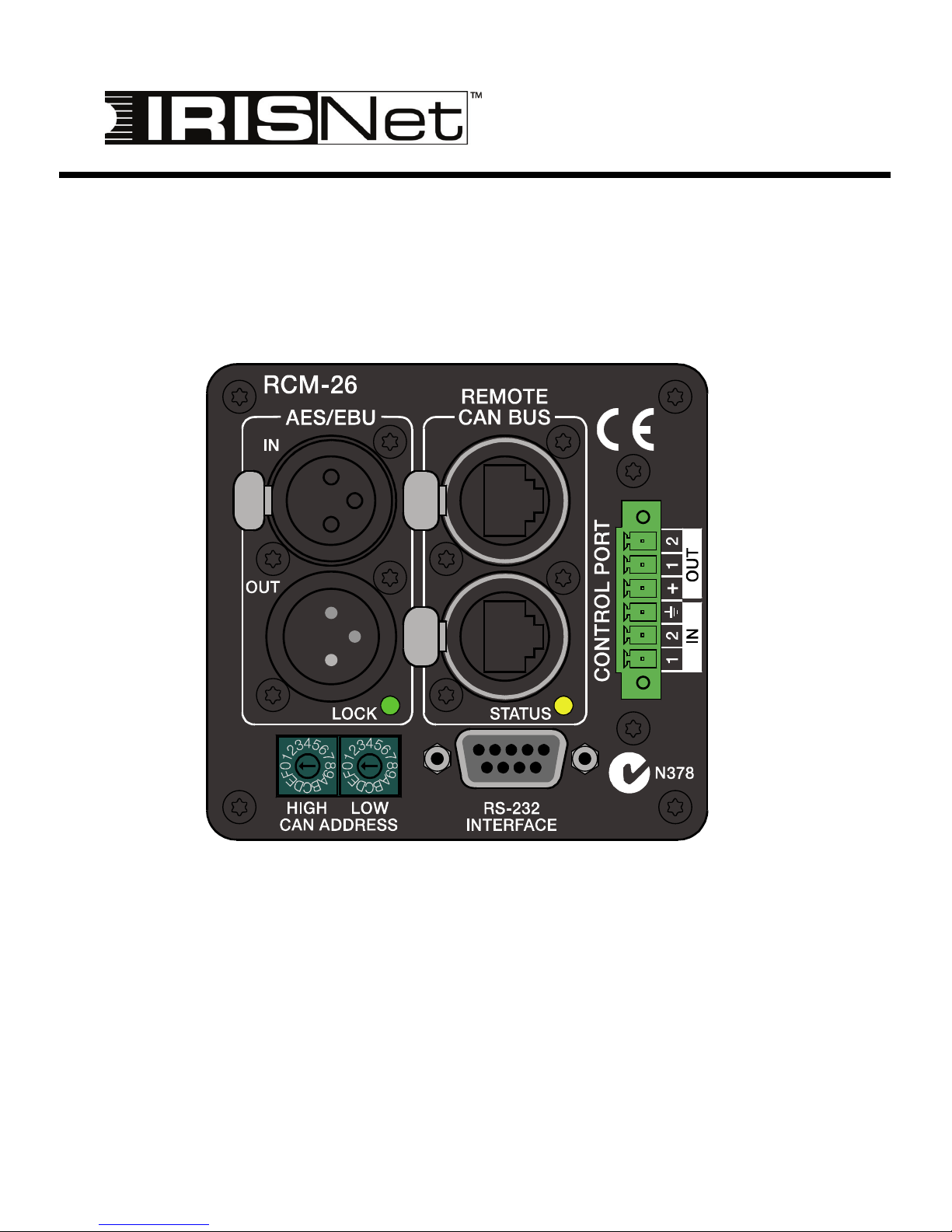
2 Controls and Connections
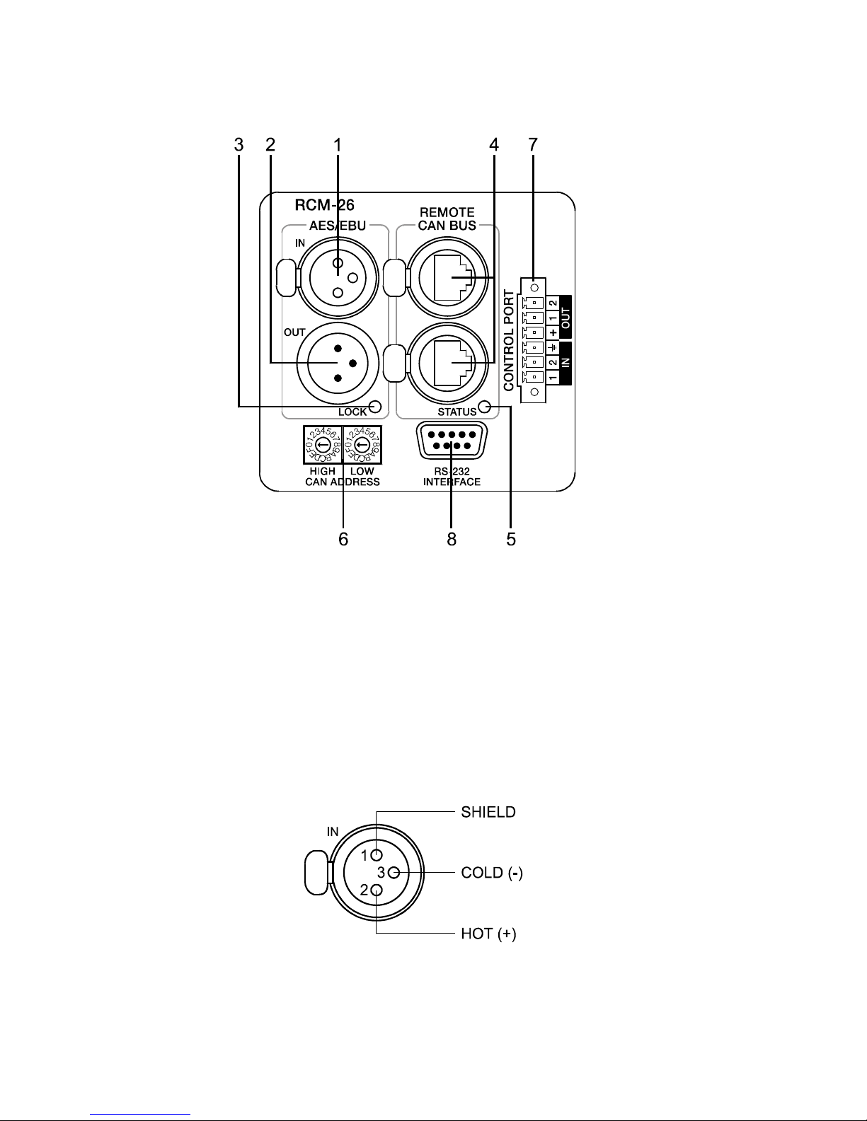
1, AES/EBU-IN
A digital AES/EBU input (AES3) is provided in addition to internal analog inputs.
The digital input signal has to be connected to the AES/EBU IN connector. The
AES/EBU input is a balanced transformer-isolated input. A sampling rate
converter translates the input signal to match the internal sampling rate.
However, the possibility to synchronize the RCM-26 to an external sampling rate
exists as well. For further details, please refer to the IRIS-Net™ help files. The
following illustration shows the pin-assignment of the input socket.
Illustration 2.1: Pin-assignment of AES/EBU-IN
12
RCM-26 Remote Control Module
Owner’s Manual
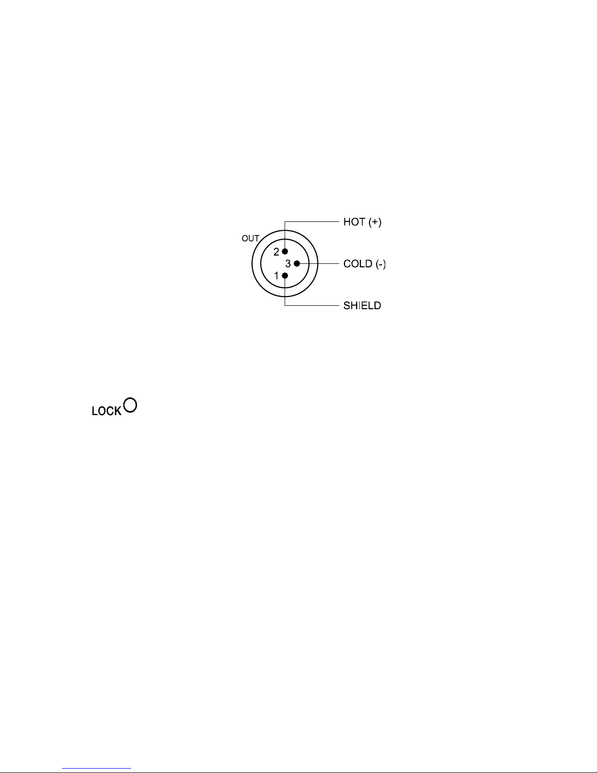
2, AES/EBU-OUT
The AES/EBU OUT connector allows looping-through the digital audio signal to
other RCM-26 modules. The digital input signal gets internally buffered and
preprocessed (level matching / slew rate) before it is output via the OUTconnector. This allows fairly simple wiring between modules, without the need
for AES/EBU distribution amps as they are usually used.
The RCM-26 has a bypass-relay, which, in case of damage (e.g. power outage),
connects the AES/EBU IN signal through to AES/EBU OUT. This ensures
trouble-free operation of downstream remote amps.
3, LOCK-LED
The LOCK-LED lights green as soon as the AES/EBU input has
been synchronized to the incoming signal and thus proper audio
transmission has been established. The LOCK-LED is dimmed with
no digital audio signal being present at the input or the internal PLL
not having locked on to the incoming signal. The audio signal gets
muted when the digital input has been selected.
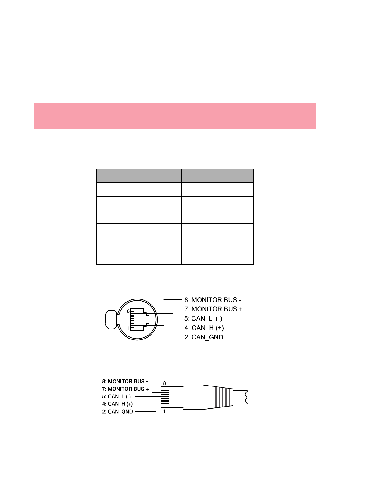
4, REMOTE CAN BUS Connection
The RCM-26 module provides two Neutrik EtherCon® RJ-45 sockets for
connecting to the REMOTE CAN BUS. These sockets are connected in parallel
and serve as inputs as well as for daisy-chaining the devices on the remote
network. Cabling in a rack system can be established using commercially
available RJ-45 network cables. However, CAN guidelines have to be observed
for longer cable lengths. Both ends of the CAN-bus must be terminated using
120 Ω terminating plugs. For comprehensive information and instructions on
cabling and bus length, please refer to the “CAN Bus principles“ paragraph,
starting on page 18. Along with the CAN bus, network cabling also carries a
balanced audio monitoring signal. This monitor bus allows software-controlled
Illustration 2.2: Pin-assignment of AES/EBU-OUT
13
RCM-26 Remote Control Module
Owner’s Manual
monitoring of input or output signals of all power amps in the remote network,
without the need for additional wiring. Nominal output level is +6 dBu (1.55 V)
and maximum output level is +21 dBu (8.7 V).
The CAN bus allows using different data rates, whereas the data rate is
inversely proportional to the bus length. For smaller network setups, data rates
can be as high as 500 kbit/s. For broader networks, reducing the data rate
becomes necessary (down to the minimum data rate of 10 kbit/s).
The following table illustrates the relation between data rate and bus length or
network size. The use of CAN repeaters is strongly recommended for busses
that exceed 1000 meters in length.
NOTE:
The data rate of the CAN Bus is preset to 10 kbit/s.
Transfer rate (in kbit/s) Bus length (in m)
500 100
250 250
125 500
62,5 1000
20 2500
10 5000
Tabelle 2.1: Transfer rate and bus length
Illustration 2.3: Pin-assignment of CAN jack
Illustration 2.4: Pin-assignment of CAN plug
14
RCM-26 Remote Control Module
Owner’s Manual
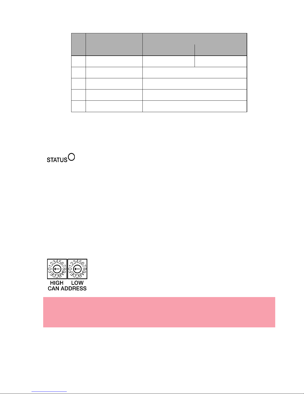
5, STATUS LED
The STATUS-LED is for monitoring the communication on the
CAN bus. The LED blinks rhythmically every 3 seconds, when the
module’s address is set to “00“, which means that it is
disconnected from the CAN bus and software control. The LED
blinks rhythmically in intervals of one second, when an address in
the range of 01 to 250 has been assigned to the module and there
has not yet been any activity on the CAN bus. As soon as
communication on the CAN bus is recognized, the LED lights for
at least 100 ms, when the power amplifier sends data on the CAN
bus.
6, ADDRESS Selector Switch
The two address selector switches are for setting the network
address of the RCM-26. CAN networks support addresses in
the range of 01 to 250 (FA hex). Addressing has to be carried
out in the hexadecimal number system. The LOW selector
switch sets the lower digit, while HIGH sets the higher digit.
Pin Name
Colour
T568A T568B
2 CAN_GND Green Orange
4CAN_H(+) Blue
5 CAN_L (-) Blue striped
7 MONITOR BUS + Brown striped
8 MONITOR BUS - Brown
Table 2.2: Overview CAN plug
CAUTION:
Each address may exist only once in a system. Otherwise,
network conflicts may arise.

15
RCM-26 Remote Control Module
Owner’s Manual
Address 0 (00 hex, delivery status) disables remote communication between the
RCM-26 and the bus. The module does not appear in the system, even though
it is physically connected to the CAN-bus.
HIGH LOW Address
0 0 Stand-alone
0 1...F 1...15
1 0...F 16...31
2 0...F 32...47
3 0...F 48...63
4 0...F 64...79
5 0...F 80...95
6 0...F 96...111
7 0...F 112...127
8 0...F 128...143
9 0...F 144...159
A 0...F 160...175
B 0...F 176...191
C 0...F 192...207
D 0...F 208...223
E 0...F 224...239
F 0...A 240...250
F B...F reserved
Tabelle 2.3: CAN addresses

16
RCM-26 Remote Control Module
Owner’s Manual
7, CONTROL PORT
The CONTROL PORT of the RCM-26 provides two
control inputs, two control outputs and reference
connections for +5V and ground. The control inputs
are configurable via IRIS-Net™. They can be used
for example for switching between power on /
standby modes, switching between presets or to
control parameters. The two control contacts IN1 and IN2 are internally
connected via pull-up resistors and carry +5V (open). The control inputs can be
activated using external switches, pushbuttons or relays to connect them to
ground potential (pin 3). The two control outputs OUT1 and OUT2 are open
collector outputs, which are highly resistive in the non-active state (off). In active
state (on) the outputs are connected to ground. The control outputs are
configurable via IRIS-Net™ and are used to signal internal states. LEDs,
indicators or relays can be driven directly. The +5V reference connector
provides voltage supply for connected components.
8, RS-232 Interface
The RS-232 interface is for interconnecting the RCM-26 module and multimedia control systems or facility management systems. All parameters can be
controlled and queried via RS-232 interface. Communication is realized through
the use of ASCII-protocol. Implementation of this protocol is rather simple.
Programming notes and a complete protocol description are included in the
IRIS-Net™ documentation. The following illustration shows the pins of the RS232 interface that the RCM-26 uses. The length of the RS-232 cable that is
employed to connect the RCM-26 to another device should not exceed 15
meters.
CAUTION:
The maximally allowable current at the +5V output is 200 mA.
Illustration 2.5: Pin-assignment of RS-232 Interface
17
RCM-26 Remote Control Module
Owner’s Manual
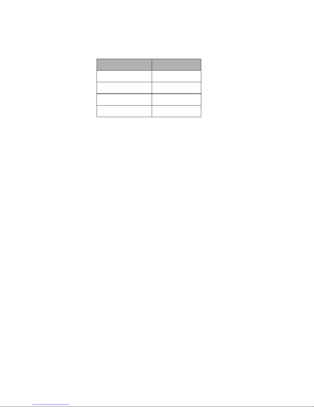
The following table shows the factory-fixed settings of the RCM-26’s RS-232
interface. The connected device (e.g. a PC with terminal program, multi-media
control software) needs to be identically configured for data transfer to work
properly.
Parameter Value
Data bit 8
Parity bit -
Stop bit 1
Transfer rate 19200 bit/s
Table 2.4: Parameter of RS-232 Interface
18
RCM-26 Remote Control Module
Owner’s Manual
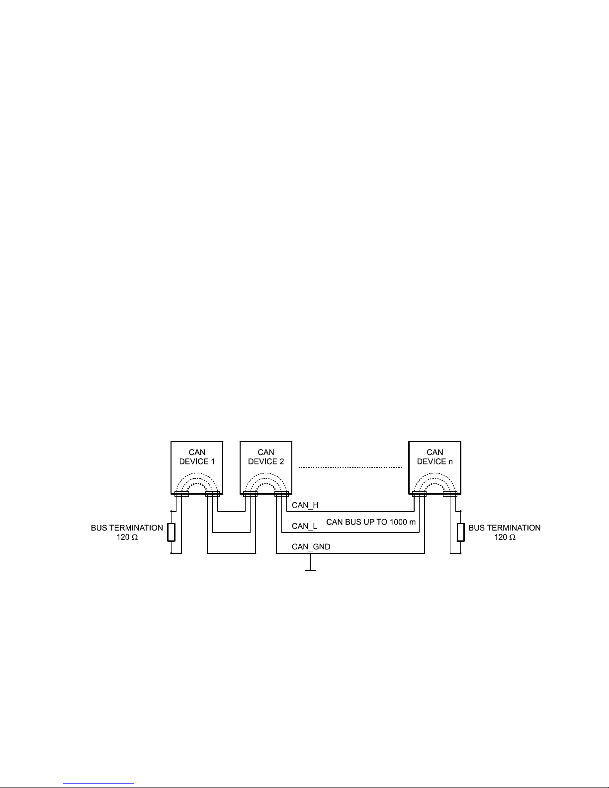
3 CAN Bus Principles
The network topology used by the CAN bus is based on the so-called “bus or
line topology”, i.e. all participants are connected via a single two-wire cable
(Twisted-Pair cable, shielded or unshielded) with the cabling running from one
participant on the bus to the next, allowing unlimited communication among all
devices. In general, it does not matter if the bus member is a RCM-26, a USBCAN converter or another device. Thus, the RCM-26 can be connected at any
place of the CAN bus. In total, up to 100 devices can be connected to one CAN
bus.
The CAN bus has to be terminated with a 120 Ω terminating resistor at both
ends. If the termination is missing or an improper resistor value is used,
network errors can occur as a signal is reflected on the bus at both bus ends.
Because of the superposition of the reflection with the original signal, the
original signal is blurred. This may result in the loss of data. In order to prevent
or minimize reflections at the bus ends, terminators are used as they "absorb"
the energy of the signal.
Since the CAN interfaces of all EVI Audio appliances are galvanically separated
from the rest of the circuitry, network cabling also carries a common ground
conductor (CAN_GND) ensuring that all CAN-interfaces in the network are
connected to a common ground potential.
By using a CAN bus repeater a connection between two independent and selfcontained CAN bus systems can be created. Thus, the following can be
achieved:
• Increase of the max. number of members
A maximum of 100 devices can be connected to one CAN bus. This number
Illustration 3.1: Bus Topology of the CAN bus
19
RCM-26 Remote Control Module
Owner’s Manual
can be increased up to 250 by connecting several CAN bus systems. This
limitation of exactly 250 devices results from the addressing scheme used
by the CAN bus. The addressing scheme allows the allocation of a maximum of 250 different CAN device addresses.
• Improvement of signal quality
With CAN bus systems, whose bus length exceeds 1000 meters, a CAN
bus repeater should be used. The CAN bus repeater accomplishes a signal
processing and a reinforcement of the bus signals. The internal running
time of the repeaters of approx. 150 ns corresponds to an extension of the
bus over approx. 45 meters.
• Creation of alternative network topologies
By using one or several repeaters, not only the above-mentioned bus topo-
logy, but the creation of other network topologies are also possible.
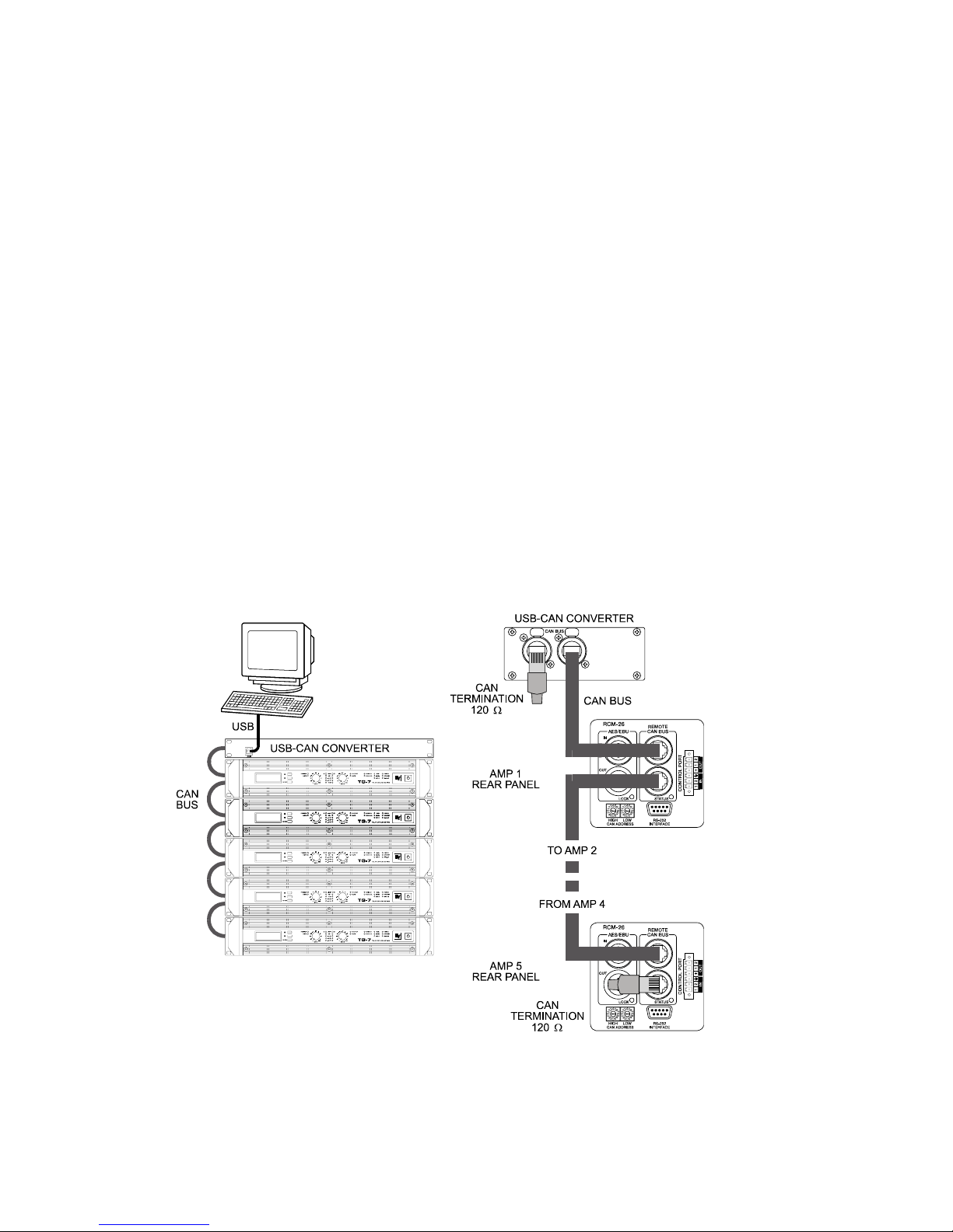
3.1 System Examples
The following illustrations show examples of the data-bus wiring for different
sizes of CAN-bus networks.
Illustration 3.2: System with 5 power amps (with RCM-26) and 1 USB-CAN-Converter. Termination plugs at the USB-CAN-Converter and the RCM-26 of amp 5
20
RCM-26 Remote Control Module
Owner’s Manual
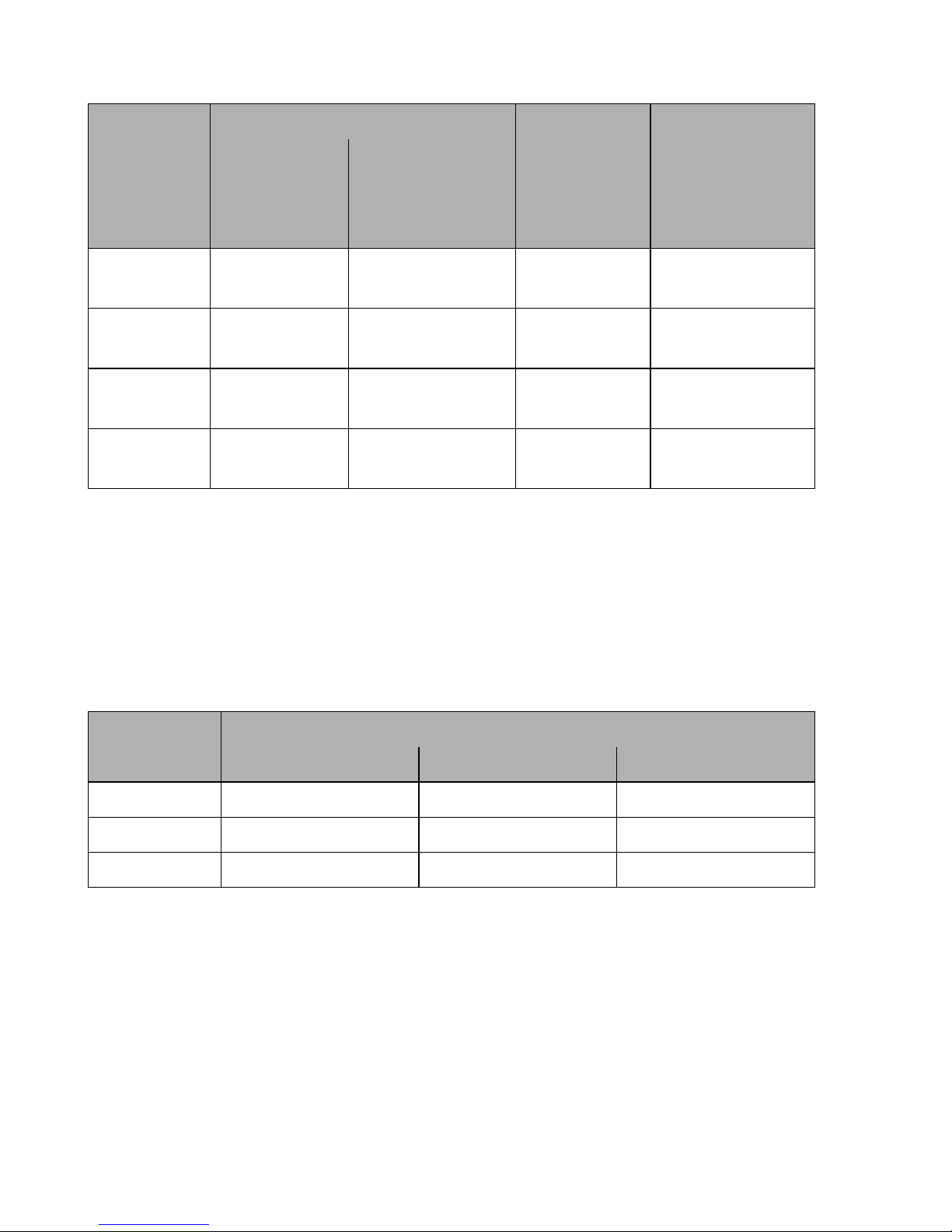
3.2 Performance Specifications
According to the ISO 11898-2 standard, CAN-bus data transfer cabling has to
be carried out using Twisted-Pair cables with or without shielding providing a
characteristic impedance of 120 Ω. Both ends of a CAN-bus need to be
terminated with 120 Ω termination-plugs. The maximum bus-length depends on
the actual data transfer rate, the kind of data transfer cable being used, as well
as the total number of participants on the bus. The following table shows the
most essential requirements for CAN-networks consisting of up to 64
participants.
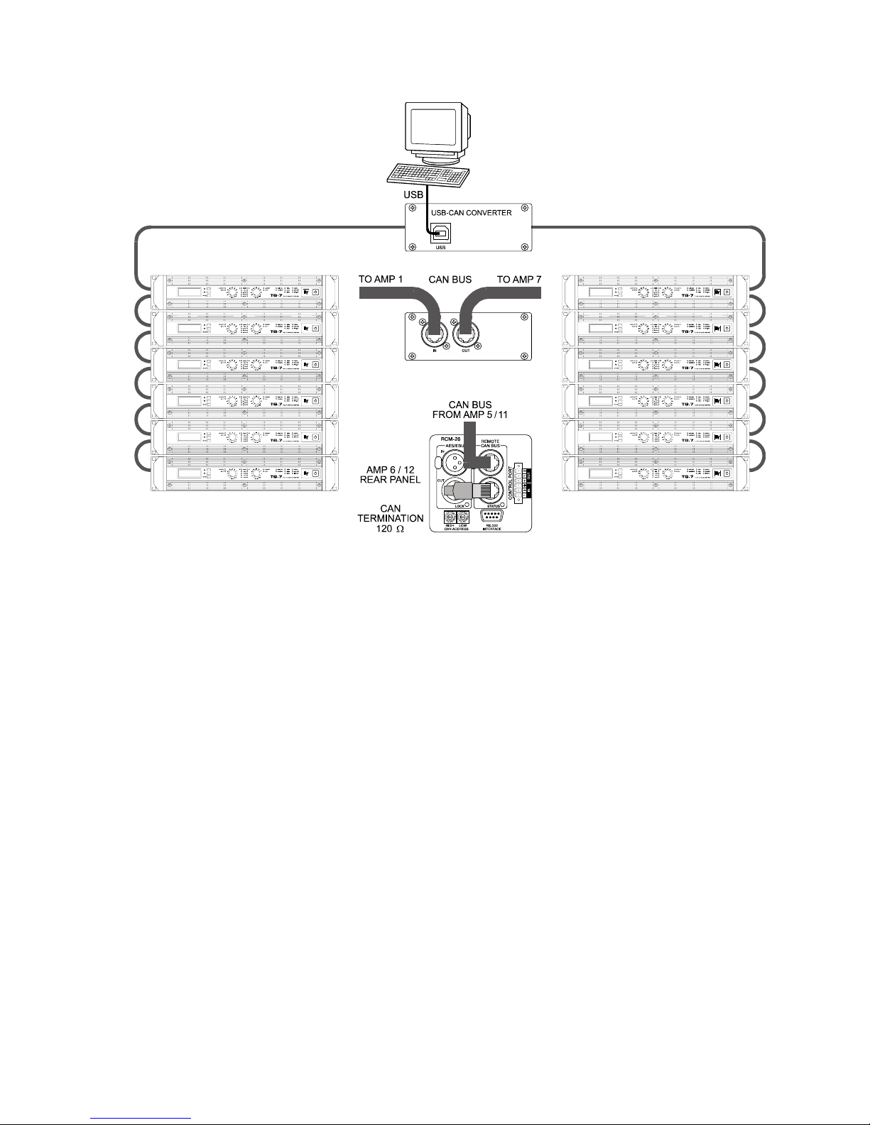
Illustration 3.3: System with 2 amp-racks and 1 USB-CAN-Converter. Terminati-
on plugs at amp 6 (first unit on the bus) and amp 12 (last unit on the bus)
21
RCM-26 Remote Control Module
Owner’s Manual
* With longer cables and many participants on the CAN-bus, termination
resistors with higher impedance than the specified 120 Ω are recommended to
reduce the ohmic load of the interface drivers and therefore the voltage drop
between the two cable-ends.
The following table is meant for first assessment of necessary cable diameters
for different bus lengths and bus-participant numbers.
Additionally, the length of branch lines - for participants that are not directly
connected to the CAN-bus - is also of importance. For data transfer rates of up
to 125 kbit/s, the maximum length of a single stub cable should not exceed 2
meters. For higher bit rates a maximum length of only 0.3 meter is still
permissible. The entire length of all branch lines should not exceed 30 meters.
Bus Length
(in m)
Data Transmission Cable
Termination
(in Ω)
Max. Data
Transfer Rate
Resistance
per Unit
Length
(in mΩ/m)
Cable Diameter
0...40 < 70
0,25...0,34 mm²
AWG23, AWG22
124
1000 kbit/s
at 40 m
40...300 < 60
0,34...0,6 mm²
AWG22, AWG20
127
500 kbit/s
at 100 m
300...600 < 40
0,5...0,6 mm²
AWG 20
150...300*
100 kbit/s
at 500 m
600...1000 < 26
0,75...0,8 mm²
AWG 18
150...300*
62,5 kbit/s
at 1000 m
Bus Length
(in m)
Number of Units on the CAN-Bus
32 64 100
100 0,25 mm²/AWG24 0,34 mm²/AWG22 0,34 mm²/AWG22
250 0,34 mm²/AWG22 0,5 mm²/AWG20 0,5 mm²/AWG20
500 0,75 mm²/AWG18 0,75 mm²/AWG18 1,0 mm²/AWG17

22
RCM-26 Remote Control Module
Owner’s Manual
General Note:
• As long as only short distances (up to 10 meters) are concerned, common
RJ-45 patch cables with a characteristic impedance of 100 Ω (AWG 24 /
AWG 26) can be used for the cabling inside of a rack mounted system.
• The previously outlined guidelines for network cabling are mandatory as far
as the rack mounted shelve interconnection or fixed installations are
involved.
BEDIENUNGSANLEITUNG
RCM-26
Remote Control Module
 Loading...