

IRIS ID iCAM4000, iCAM4000R, iCAM4010-E1, iCAM4010R-E1, iCAM4010-H1 Hardware Manual
...
iCAM IP Address Configuration: To communicate over an Ethernet based network, the
iCAM requires an IP address to be configured. By default factory settings of an iCAM is set to
the address of 192.168.5.100 with a subnet mask of 255.255.255.0. This IP address can be
changed from the iCAM web configuration screen. For details on viewing/changing an IP
address of an ICAM please refer to the Software Installation Guide.
IP Announcement: The current iCAM IP address can be determined using the IP announcement function. To activate this function press the right tilt button UP on the front face of the
iCAM. Hold this tilt until the unit face tilts to the UP position and continue to hold for at least
ten seconds. Through the internal iCAM speaker an audible IP will be announced indicating
the current IP address setting programmed in the unit. This function can be enabled or
disabled through the web interface if desired.
iCAM Reset: The current iCAM contains a reset button located directly to the right of the
positive and negative power connectors. This reset button when depressed for over 3
seconds will reset the iCAM to the factory default settings. Such settings include the IP
address, and web interface login credentials.
iCAM4000 Model Variations
Base RoHS comp. HID iClass IE Smart-ID
Smartcard Reader
iCAM4000
What’s in the box
• iCAM4000 - IrisCamera
• Power Adapter
Input: 110~240V AC - 1.5AMP 50/60Hz
Output: 12V DC - 5.0AMP
• Power Cable for 110V
• CAT5e Ethernet Cable
• Hardware Guide
• Security Screw Wrench
Required Equipment (not included with iCAM4000)
• Server Computer (refer to the software manual for details)
• Ethernet Switch
• Ethernet Wiring
• Uninterruptible Power Supply (strongly recommended)
• The recommended mounting height for the
iCAM4000 is 142cm (56 inches) from the floor to
the bottom of the unit. This mounting height can
be adjusted to accommodate the height of the
average user at the installed location.
• High amounts of ambient light must be avoided.
Intense light sources such as sunlight or halogen
lamps may reduce the image capture performance
of the iCAM, this may result in an increased
“failure to acquire” rate.
• The iCAM is not weatherproof and must not be
exposed to precipitation or extreme temperatures.
An enclosure may be used to protect the unit if
required. See www.lgiris.com – Support & Service
for more information.
• All system components must be powered through
Uninterruptible Power Supplies (UPS). UPS must
provide power line filtering as well as power back-up
operation.
• Each IrisAccess
®
system component if on an Ethernet
network system must have a statically assigned IP
address.
iCAM4000 Hardware Guide version 1.00
Packing List
Installation Guidelines
The iCAM4000 requires at least the following wires:
• Ethernet network wiring to connect with the network switch to communicate to the Iris-
Server or an ICU.
* Note: For systems consisting of only an IrisServer and iCAM may use an Ethernet cross
over cable to connect the iCAM directly to the IrisServer computer.
• Power (12VDC +/-10% and 2.5Amps MAX)
* Note: If not using the supplied power adapter, use of a stable power supply and proper
gauge wire is required. Wire length voltage drop must be accounted for in order to maintain
the correct 12VDC @ 2.5A power with the iCAM connected. (Ex. 50 feet of 16 gauge copper
wire requires a supply voltage of 13VDC to provide 12VDC power at the iCAM.)
1. When recessed mounting (bracket
optional), leave 6mm (1/4”) of extra
space above the marked hole so
when mounting the back plate it allows
the iCAM to slide down onto the
installation plate tabs. Route the power
line, network line, and other necessary
cables through the back plate hole.
2. Route the power line and other necessary
cables through the back plate hole.
3. Use the appropriate fasteners for the
material in which the iCAM will be
mounted, secure the back plate.
4. Attach the wires from the 12VDC power
supply to the screw terminal connections. The +12VDC (white wire: VCC) power connects
to the + (positive) terminal, whereas the 12VDC ground (black wire: GND) connects to the –
(negative) terminal. Use the appropriate fasteners for the material in which the iCAM will be
mounted, secure the back plate.
5. Connect the CAT5/RJ45 network wire into the LAN port (CN10) of the iCAM. Make sure
that the RJ45 connector locks securely into the LAN port. (Skip this step if not connecting to
network)
6. Wiegand and/or relay options should be connected at this time. Please see section 5 for
more details.
7. Close front cover and gently slide the iCAM downwards over the back plate. Fasten with
two security screws on the bottom of the unit.
* Note: The iCAM includes two tamper switches. One switch is located on the rear of the
iCAM to detect removal from the wall or enclosure from which it is installed. A second tamper
switch is located behind the front plate to detect tampering with the front of the unit. During
installation be sure that the rear tamper switch is in a position which can detect unit removal
from the wall or enclosure.
Installation
iCAM IP Settings
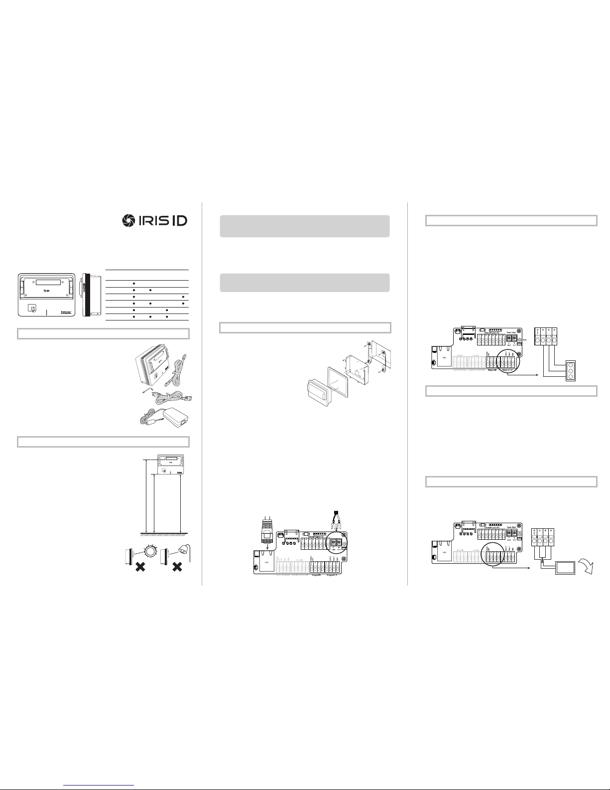
Wiegand Output from iCAM4000:
The Wiegand Output from the iCAM4000 can be used with 3rd party devices capable of receiving Wiegand data; this output emulates a typical Access control Card Reader. Configuration
of this output is provided through the iCAM web-interface. See the above image for general
wiring of Wiegand Output to an Access Control Panel.
Wiegand Specifications:
• Wiegand output uses 3 wire interface (Data 1, Data 0, and Ground),
• Maximum wire length from iCAM to Access Control Panel is 500 feet (152m).
*Note: Using IrisAccess EAC software, Wiegand output is available from either the iCAM, ICU
with
WIB board, or a DCU.
Available iCAM Wiegand Output
• A Wiegand input is available on the iCAM for connection from Proximity card readers.
• This connection provides 12-volt DC power that can be used be used to directly power the attach ed card reader.
• Configuration of this input is provided through the applicable software application and iCAM web
interface. See image for general wiring of a Prox card reader to an iCAM.
Optional Prox Card
IMPORTANT: IT IS RECOMMENDED THAT THE IRISACCESS SYSTEM BE PLACED ON A PRI-
VATE NETWORK SEPARATE FROM GENERAL CORPORATE OR PUBLIC ACCESS. SYSTEM
PERFORMANCE AND STABILITY MAY BE AFFECTED DEPENDING ON AMOUNT OF GENERAL NETWORK TRAFFIC
IMPORTANT: IT IS RECOMMENDED TO USE THE POWER ADAPTER SUPPLIED WITH THIS
PRODUCT. AN OVER OR UNDER VOLTAGE APPLIED TO THIS PRODUCT MAY CAUSE PERMANENT DAMAGE AND VOID THE WARRANTY.
bottom of
mirror
floor
61”
(155mm)
56”
(142mm)
RECOMMENDED
Power Supply
Connector
Data 0
Data 1
Ground
Access
Control
Panel
Wiegand Out
Reset
Power Input
Ethernet
Cable
iCAM4000R
iCAM4010-E1
iCAM4010R-E1
iCAM4010-H1
iCAM4010R-H1
Power (+12V)
Ground
Data 1
Data 0
Wiegand IN
External
Card Reader

iCAM Tamper Alarm Relay
24-Hour Monitored Alarm Zone
Connecting a tamper relay to either an active 24-hour monitored alarm system, or a passive
alarm designed to alert locally can be configured with the applicable software. In the event that
the iCAM is tampered, the alarm will be triggered when configured as illustrated.
External Sound or Audible Device
Connecting a tamper relay to an audible device such as a siren locally positioned in your
environment allows immediate recognizable audible input that the iCAM may be potentially
compromised.
The iCAM is available with an optional integrated Smartcard reader. When an integrated
Smartcard is installed in the iCAM, the card reader symbol appears in the front of the
iCAM. The built-in card reader is pre-wired and enabled within the iCAM.
Two type of card readers are available:
• HID iCLASS (iCLASS)
• Integrated Engineering (MiFare / DesFire)
If desired, a compatible external card reader may be connected to the iCAM.
In the iCAM there are two available dry-contact relays that can be used for purposes such as
door lock control, external indicators, control of external systems, and external audible alerts
(as some examples). The functionality of the relays are determined by the software application used to control the iCAM. For more detail on these available options please refer to the
applicable software installation guide.
iCAM Relays:
Both iCAM relays have the normally open and normally closed contacts available. Relays one
and two are independent from each other and can be set for different functions.
Typically relay one is used for door-lock control, whereas this relay is triggered upon successful identification or verification of the user. Typically relay two is used for iCAM tamper
output, whereas this relay activated when the iCAM tamper switch is triggered.
*Note: For security purposes, it is not recommended to use the iCAM relay output for direct
door-lock control.
Direct Door Control Wiring:
The Door-Strike Diagram shows an example of an iCAM connected to the Negative wire from
the 3rd party door strike connected to R1_NC, and the Positive wire from the 3rd Party
required external power supply connecting to R1_COM connectors. (Completing the
connection through to the door strike is then required as per the instructions provided by the
door strike manufacturer.)
The Magnetic Lock (MAG-lock) diagram shows an example of an iCAM connected to the
Negative wire from the 3rd party MAG-lock connected to R1_N.O., and the Positive wire
from the 3rd Party required external power supply connecting to R1_COM connectors.
(Completing the connection through to the MAG-lock is then required as per the instructions
provided by the MAG-lock manufacturer).
MAG
Lock
Door
Strike
Diagram
Power
Supply
Power
Supply
Door Strike
Egress
(inside to
secure area)
*Note: If working with a non-ROHS compliant iCAM the N.O. and N.C. are reversed. The
diagrams in this guide are drawn to the correct connections of the RoHS compliant iCAM.
Disclaimer: Only knowledgeable insured professional installers should attempt to install
Magnetic locking systems with use of the iCAM. Consult with your fire Marshall and local
town/county code requirements to guarantee adherence to specific local ordinances and
restrictions. LG cannot be held responsible for regulatory issues, and mandated legal require-
ments applicable to the potential installation of any 3rd party products compatible with the
ICAM.
External Indicator Light
External indication lights can be connected for a more visual indication of a users acceptance at
the iCAM. The diagram shows an example of external indicator lights connected to the
Negative wire from the 3rd party external power source and the positive wire of the power
source connected to the COM of relay one.
The Green light which is used to indicate a successful identification/verification is connected to
the N.O. connection of relay one. The red light which is used to indicate a non-identification
condition remains constantly lit unless a green light condition occurs (Red light is connected to
the N.C. of the relay one).
Available Relay Outputs
Optional Smartcard Readers Available iCAM External Tilt Control
Technical Support
Red
Green
Wiegand IN
Tilt (RoHS only)Relay 2
Tamper
Relay 1
Door
Control
GPI/0_4
GPI/0_3
R2_NO
R2_COM
R2_NC
R1_NO
R1_COM
R1_NC
Wiegand OUT
General Purpose I/O
General Purpose I/O
Additional information and Technical assistance is available on the Iris ID System’s support
web site at www.irisid.com, click on Support & Service then Technical Support.
12V DC OUT
Ground
RxD
TxD
Wiegand INSmartcard Reader
Smartcard Reader IF
Serial RS-232/422/485
Wiegand OUT
iCAM External Tilt Control – Wiring
When firmware enabled, the GPIO connections on the iCAM can be used to control the tilt
position of the camera module. This tilt feature is available on the RoHS compliant iCAM
series of iris cameras.
It is recommended that only momentary switches are used for the tilt control and that the
wire length between the switches and iCAM does not exceed 15 meters (50 feet).
iCAM External Tilt Switch Operation
The External Tilt Switch allows the iCAM user to remotely control the tilt operation of the
iCAM camera module. This feature is useful if the iCAM is installed where the tilt switches
on the face of the camera module are inaccessible or inconvenient to the user.
Connection and operation of the External Tilt Switches does not disable or alter the operation
of the tilt switches located on the face of the iCAM camera module.
Switch Wiring for the iCAM Series Camera
The external tilt switches are to be connected to the GPIO connections located on the
interface board inside the iCAM. The GPIO are located on the General Purpose Input /Output
port (labeled CN605).
* Note: The PINs on the iCAM interface board are numbered from left to right.
Up Switch: The up tilt switch is to be wired between the GND (Ground) connection (located
at PIN 5 of the Serial RS232/422 port – CN607) and the GPIO3 connection (located at PIN 7
of the General Purpose I/O port (CN605)).
Down Switch: The down tilt switch is to be wired between the GND (Ground) connection
(located at PIN 5 of the Serial RS232/422 port – CN607) and the GPIO4 connection (located
at PIN 8 of the General Purpose I/O port (CN605)).
Wiegand IN
SmartCard Reader
Serial RS-232/422/485
Wiegand OUT
Up Switch to GPIO_3
Down Switch to GPIO_4
Momentary
Switches
UP
DOWN
R2_COM
R2_NO
R2_NC
R2_COM
R2_NC
R2_NO
Iris ID Systems, Inc.
www.irisid.com
7 Clarke Drive, Cranbury, NJ 08512, USA
Tel. 609-819-IRIS(4747) Fax. 609-819-4736
©2010 Iris ID Systems, Inc. All rights reserved. Design and specification subject to change without notice.
formerly
Document # IRISIDEAC-04-0100-0410
 Loading...