

Page 1

Version 1.00. March 2012. ©Iris Innovations Limited. www.boat-cameras.com. info@boat-cameras.com
TED65
Intuitive Touch Screen PTZ Controller
User Guide
Page 2

Contents
Page
3! Warnings and Regulatory Information
4! Introduction
5! Unit Dimensions
6! Installation Instructions
7! Fixing Instructions
8! Power and Data Connections
8! Back Panel Details / Connections
9! Log In Screen
10! Camera Control Screen
11! Main Menu Screen
12! Thermal Palette Select (Iris Thermal Cameras Only)
13! Camera Memory Tours
14! Camera memory Tours - Setting Up
15! Image Flip
16! Scene Modes (Iris Thermal Cameras Only)
17! Scan and Sweep
18! QIK Presets
19! User Presets
20! Camera Select
21! Notes
22! Back Cover
Version 1.00. March 2012. ©Iris Innovations Limited. www.boat-cameras.com. info@boat-cameras.com
Page 3

Warnings & Regulatory Information
To reduce possible heat related damage do not block the airflow or ventilation to the unit, especially the rear,
and do not install in areas that are likely to become hot.
Although the front of the unit is water resistant, the rear is not, so do not expose to moisture or water.
Do not use harsh chemicals or cleaning solvents to clean the devise.
Do not attempt to open the device.
Unauthorized modifications or attachments could damage the device an may violate regulations governing
radio devices.
Avoid dropping, knocking or shaking the device. Rough handling can break internal circuit boards and fine
mechanics.
Observe correct polarity when connecting power and data. Failure to do so could result in damage to the
unit.
Disposal of Waste Equipment by Users in Private Household in the European Union.
This symbol on the product or its packaging indicates that it must not be disposed of with your
other household waste. Instead, it is your responsibility to dispose of your waste equipment
by handing it over to a designated collection point for the recycling of waste electrical and
electronic equipment. The separate collection and recycling of your waste equipment at the
time of disposal will help to conserve natural resources and ensure that it is recycled in a
manner that protects human health and the environment. For more information about where
you can drop off your waste equipment for recycling please contact your local city office, your
household waste disposal service or the shop where you purchased the product.
This device has been tested and found to comply with the limits for a Class B digital device,
pursuant to Part 15 of the FCC rules. These limits are designed to provide reasonable
protection against harmful interference in a residential installation. This equipment generates,
uses and can radiate radio frequency energy and, if not installed and used in accordance
with the instructions, may cause harmful interference to radio or television reception.
However, there is no guarantee that interference will not occur in a particular installation. If
this equipment does cause interference to radio and television reception, which can be
determined by turning the equipment off and on, the user is encouraged to try to correct the interference by
one or more of the following measures: Reorientate or relocate the receiving antenna; Increase the
separation between the equipment and the receiver, connect the equipment to an outlet on a different circuit
from that to which the receiver is connected; consult the dealer or an experienced radio / TV technician for
help.
We hereby declare that the product is in compliance with the essential requirements and
other relevant provisions of European Directive 1999/5/EC (Radio and telecommunications
terminal equipment Directive).
Version 1.00. March 2012. ©Iris Innovations Limited. www.boat-cameras.com. info@boat-cameras.com
Page 4
Introduction
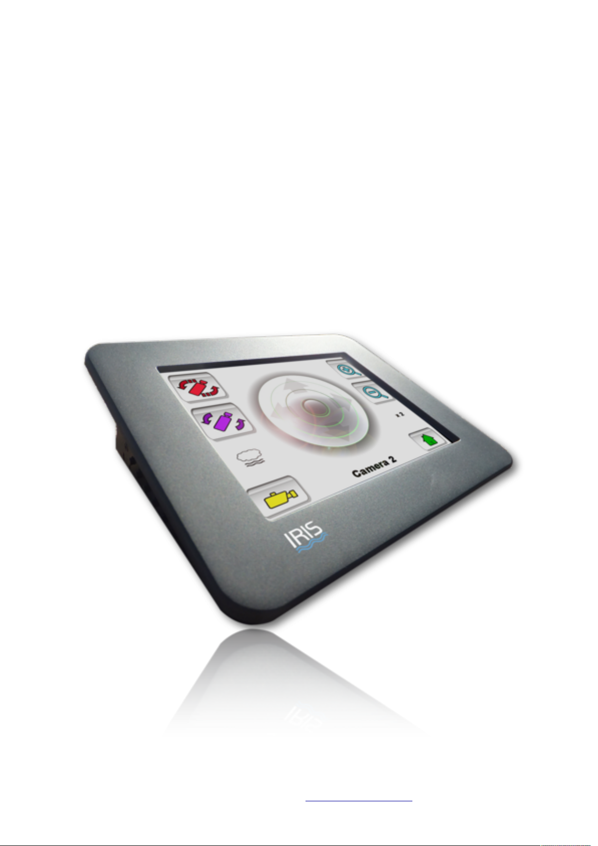
TED65 is an intuitive control devise designed especially to control Iris Innovations range of Pan Tilt Zoom
(PTZ) and Thermal Imaging PTZ cameras.
Featuring a high bright 6.5” water resistant touch screen, control of the cameras PTZ functions and other
enhanced features is achieved at the touch of a button.
Set up and call User Preset Memory positions, select camera scans and tours, choose colour palettes and
scene modes and much more, all from the intuitive multi-layered interface.
The TED65 is based around an embedded computer running dedicated software which means the unit will
be upgradable providing future-proofing.
Version 1.00. March 2012. ©Iris Innovations Limited. www.boat-cameras.com. info@boat-cameras.com
Page 5
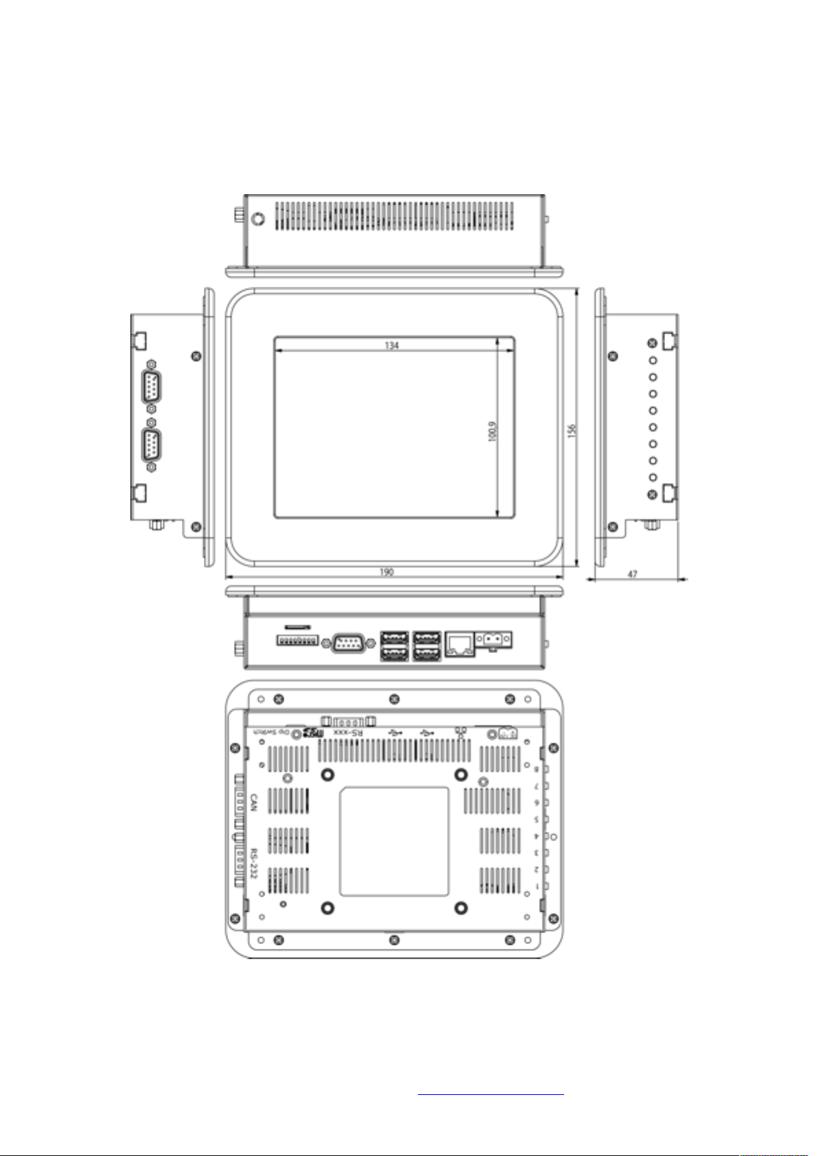
Unit Dimensions
Version 1.00. March 2012. ©Iris Innovations Limited. www.boat-cameras.com. info@boat-cameras.com
Page 6
Installation Instructions
TED65 is designed to be panel mounted into a dashboard or helm. The front of the unit is water
resistant but the rear of the unit isnʼt, so if installing in an external helm ensure a suitable water
resistant silicone sealant is used around the panel cut-out when fixing the unit in place. Also ensure
there is suitable ventilation around the back of the unit and take care not to site the devise in a
position where there is excessive heat behind the panel. Allow enough space to around the unit to fit
the data adapter and power plug.
Version 1.00. March 2012. ©Iris Innovations Limited. www.boat-cameras.com. info@boat-cameras.com
169mm
126mm
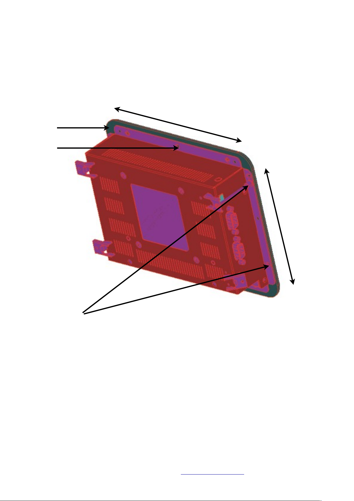
Fixing Points
The bezel is fixed onto the frame of the unit using M3 x 3mm machine screws around the
frame. To screw fix the unit into your panel remove bezel screws as required and replace
with screws that are long enough to go through the panel, through the frame and lock into
the bezel. For example, if your helm is 7mm thick, remove screws as required from the
bezel and replace with 10mm screws. 4 x M3x10mm machine screws are supplied.
Panel Cut-Out
Bezel
Frame
Page 7
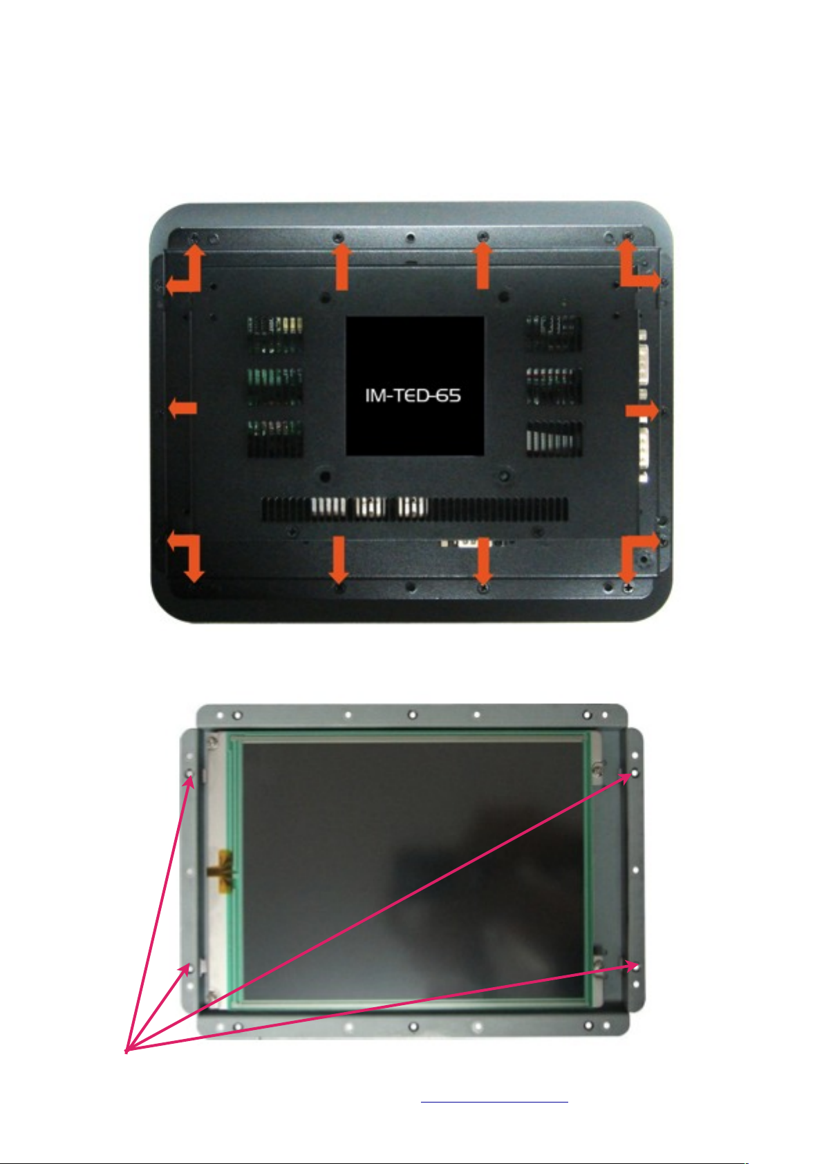
Fixing Template
Once the panel has been cut you can unscrew the bezel and use the fixing holes in
the frame to mark off your desired fixing points.
Version 1.00. March 2012. ©Iris Innovations Limited. www.boat-cameras.com. info@boat-cameras.com
View with front bezel removed.
Recommended Fixing Points.
Page 8

Power and Data Connections
Power your unit from a dedicated fuse / breaker rated at 12VDC / 600mA. The unit operates when
power to the breaker / fuse is applied. Ensure suitably rated cable is used to handle the required
current and voltage.
A DC jack/Phoenix Screw Terminal plug adapter is provided to simplify power connection. If you
decide to use this adapter ensure to observe the polarity markings shown. Connect +12vDC to the
terminal marked + and connect the Ground to the terminal marked -.
Data communications to cameras and other devices is achieved via the unitʼs serial port. An RS232
to RS485 data convertor is supplied and must be connected to the serial port. The convertor has a
DSUB9 connector that plugs directly into the serial port and screwed into place. At the opposite end
of the convertor is a convenient screw terminal block marked + and - into which the RS485 data line
is wired.
Back Panel Details / Connections
(Items listed in grey are not currently used and reserved for future use).
1. Product label with regulatory information.
2. Power Connector 12VDC 600mA (Phoenix Combicon MSTB 2.5)
3. RJ45 Ethernet Connector (LAN).
4. 2 x USB Host
5. 2 x USB Host
6. RS232 Serial Port
7. MicroSD Card Slot
8. Dip switch Bank
9. CAN Bus
10.RS232 Port
11.Mounting Hole for Wall Clamps
12.M4 Screw Hole (x4) for FDMI (VESA) mounting
Version 1.00. March 2012. ©Iris Innovations Limited. www.boat-cameras.com. info@boat-cameras.com
Power Jack Adapter
RS232/RS485 Data Adapter
Page 9

Login Screen.
Immediately from power up the unit displays the log in screen shown below.
Log in passcode is set at: 1650. Enter the passcode and press the Tick key to confirm.
Version 1.00. March 2012. ©Iris Innovations Limited. www.boat-cameras.com. info@boat-cameras.com
1 6 5 0
Page 10

Camera Control Screen.
Once logged in the main camera control screen is displayed.
To select a feature, simply touch and release the appropriate button.
To Pan and Tilt the selected camera simply touch the area in the control ball that reflects where you
want to drive the camera. The camera will move in the direction youʼve touched for as long as you
keep your finger on the screen. The control ball is scaled for speed, which means the further from
the centre of the ball you touch, the faster the camera will move in that direction.
Note: Many cameras, including the Iris PTZ16 range of cameras and thermal imaging cameras feature
proportional speed control, which means the camera speed reflects the zoom level of the camera.
When the camera is fully zoomed out, the cameras speed settings are normal, however as the
camera is zoomed in, speed settings are scaled down to make control easier.
Version 1.00. March 2012. ©Iris Innovations Limited. www.boat-cameras.com. info@boat-cameras.com
QIK Presets
User Presets
Scene Mode
Indicator
Camera Select
Camera
Control Ball
Current Camera
Main Menu
Zoom Out
Zoom In
Page 11

Main Menu.
Extended features can be accessed from the main menu.
NOTE: Available features will depend on the specifications of the particular camera you are
controlling. For example, Scene Modes and Thermal Palettes will not work with regular PTZ cameras.
Pause Image
The Pause Image button freezes the image on the screen to allow inspection. Press the key again to
un-freeze the image. All functions remain operational when the image is frozen.
Version 1.00. March 2012. ©Iris Innovations Limited. www.boat-cameras.com. info@boat-cameras.com
Thermal Palette Select Camera Memory Tours Image Flip
Pause Image
Camera ControlScans & SweepsExit to Log In Screen
Scene
Modes
Page 12

Thermal Palette Select (Iris IM-PTZ-16T Range of Thermal Imaging Cameras Only).
Iris Thermal Imagine Cameras feature multiple thermal colour palette options, all selectable from this
page.
Version 1.00. March 2012. ©Iris Innovations Limited. www.boat-cameras.com. info@boat-cameras.com
Colour Palette Select
(as labelled below)
Invert PaletteCamera Control Page Back to Main Menu
Page 13

Camera Memory Tours.
Iris PTZ16 / PTZ16T cameras feature 4 Memory Tours which are activated from this page.
Each tour is made up of up to 10 user defined positions. Once positions are stored in the cameras
memory, when a tour is activated it will sequence through each position with a short dwell time
between each position. When the tour reaches the last of the available 10 positions it will loop
through the sequence from position 1 until stopped.
The Green ʻGOʼ icons begin each tour. Tours are stopped the next time the camera is sent a Pan, Tilt
or Zoom command.
Each individual tour is set up by selecting the ʻSet-Upʼ button .
Version 1.00. March 2012. ©Iris Innovations Limited. www.boat-cameras.com. info@boat-cameras.com
Tour ʻGO!ʼ Buttons
Tour Set Up Buttons
Exit to Log In Screen Back to Main Menu
Tour Number 1 - 4
Page 14

Camera Memory Tours - Setting Up.
To set up each tour, first press the appropriate Set-Up key from the Camera Tours page (above). Next,
select the appropriate key (1 to 10) for the position you wish to store. You will then be taken to the
Camera Tour Control Page (shown below) from which you can drive the camera to the desired
position.
Once you have moved the camera to the desired position, press the ADD key to learn that position.
To delete a position that is already stored in memory, select the desired position from the List and
when the Camera Tour Control Page is displayed, press the ERASE key.
The GOTO button on the Camera Tour Control Page can be used to send the camera to the selected
position to remind you of that position.
Version 1.00. March 2012. ©Iris Innovations Limited. www.boat-cameras.com. info@boat-cameras.com
Select Position 1 - 10
Back to Main Menu
Back to Main Menu
ADD Position
GOTO Currently
stored position
ERASE Current Position
Page 15

Image Flip.
ʻFlipsʼ the video image and telemetry control, predominantly for ʻBall Downʼ installations. Iris thermal
imaging cameras can also flip the video image horizontally. This is especially useful for cameras
pointing backwards to provide a true representation of the scene.
Version 1.00. March 2012. ©Iris Innovations Limited. www.boat-cameras.com. info@boat-cameras.com
Standard Image
Vertical Flip
Back to Main Menu
Horizontal &
Vertical Flip
Horizontal Flip
Page 16

Scene Modes (Iris Thermal Imaging Cameras Only.
Iris Thermal Imaging cameras feature five pre-defined ʻScene Modesʼ, used to select the optimum
contrast and gain settings for a particular circumstance, such as Day time operation, Night time
operation etc.
The five modes, selectable from this page at the touch of a button, are:
Day Mode
Night Mode
Fog Mode
Man Over Board Mode
Marina Mode.
Each mode is represented by one of the icons below. For full description of the camera modes, refer
to the camera documentation.
Version 1.00. March 2012. ©Iris Innovations Limited. www.boat-cameras.com. info@boat-cameras.com
Day Mode
Man Over Board Mode
Fog ModeNight Mode
Marina Mode
Back to Main Menu
Page 17

Scans & Sweeps.
Iris PTZ16 cameras feature four built in scans and sweeps, ranging from a narrow sweep of 45˚ to
full 360˚ random scan as detailed below:
1. Narrow sweep:# Pans 22.5˚ in each direction from the point at which the sweep was initiated.
2. 90˚ sweep: Pans 45˚ in each direction from the point at which the sweep was initiated.
3. 180˚ sweep: Pans 90˚ in each direction from the point at which the sweep was initiated.
4. 360˚ scan: Pans randomly through 360˚.
Each scan / sweep has three speed settings; slow, standard and fast. Once initiated the camera will
not respond no any commands (other than tilt) until the scan / sweep in cancelled.
Version 1.00. March 2012. ©Iris Innovations Limited. www.boat-cameras.com. info@boat-cameras.com
Fast Speed Setting
Standard Speed Setting
Slow Speed Setting
Exit to Log In Screen Cancel Scan / Sweep Back to Main Menu
90˚ Sweep360˚ Random Scan 180˚ Sweep Narrow Sweep
Page 18

QIK Presets.
QIK presets allow the user to set or recall two memory positions instantly with a single button press.
They are useful in situations where you need to save a camera position to memory urgently without
going into the full user preset process. For example, if you are docking your boat you may use QIK
presets to store the camera position for viewing your aft quarters so you can call them at the touch
of a button without having to control the camera whilst carrying about a potentially difficult
maneuver
To store a QIK preset, move camera to the desired position, enter the QIK preset page from the
camera control page and simply press the Learn Position Button.
To recall the QIK preset position simply press the appropriate Call QIK Preset button.
Version 1.00. March 2012. ©Iris Innovations Limited. www.boat-cameras.com. info@boat-cameras.com
Call QIK Preset
Learn Position
Back to Camera Control Page
Page 19

User Presets.
The TED65 currently supports 16 user preset positions. Presets are memory locations that store the
pan, tilt and zoom settings of the camera enabling the user to recall the position at the touch of a
button.
Accessed from the camera control page, the User Preset page displays the 16 memory buttons. To
recall a preset simply touch the appropriate button and the camera will instantly move to the stored
position at full speed.
To store a preset, move the camera to the desired position from the camera control page, enter the
User Preset page, press the LEARN Preset button then select the memory location (1 - 16) you wish
to store the position.
Version 1.00. March 2012. ©Iris Innovations Limited. www.boat-cameras.com. info@boat-cameras.com
Memory Locations 1 - 16
LEARN Preset
Back to Camera Control Page
Page 20

Camera Select.
Accessible from the Camera Control Page, the Camera Select menu lets you choose which of the 16
currently supported cameras you wish to control. Simply choose the desired camera from the list
and the controller will assume control of that camera. Press the Control Selected Camera button to
drive the selected camera.
Please Note: The camera select page only currently switches control of the camera and does not
switch the video.
Version 1.00. March 2012. ©Iris Innovations Limited. www.boat-cameras.com. info@boat-cameras.com
Camera Select Buttons 1 - 16
Control Selected Camera Back to Camera Control Page
Page 21

Notes
Version 1.00. March 2012. ©Iris Innovations Limited. www.boat-cameras.com. info@boat-cameras.com
Page 22

Version 1.00. March 2012. ©Iris Innovations Limited. www.boat-cameras.com. info@boat-cameras.com
Iris Innovations Limited
Units 8 & 9 Swanwick Business Centre
Bridge Road
Swanwick
Hampshire SO31 7GB
United Kingdom
Tel: +44(0)1489 570797
email: info@boat-cameras.com
www.boat-cameras.com
 Loading...