

Page 1

V
ersion
1.00.
February
2013.
©Iris
Innovations
Limited.
www
.boat
-
cameras.com
. info@boat
-
cameras.com
1/21
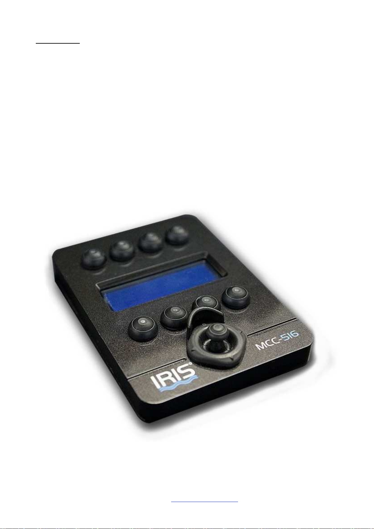
IRIS
516
Compact Marine PTZ Controller
User Guide
Page 2

V
ersion
1.00.
February
2013.
©Iris
Innovations
Limited.
www
.boat
-
cameras.com
. info@boat
-
cameras.com
2/21
Contents:
Page
3 Warnings and Regulatory Information
4 Introduction
5 Installation Instructions
Operation:
7 Power and Data Connections
8 Main Menu
9 Camera Select Menu
10 Function Select Menu
11 Lens Function Select Menu
12 Day/Night Function Menu
13 Scan Functions Menu
Thermal Functions:
14 Thermal Colour Palette Selection
15 Thermal Scene Mode Selection
Settings:
16 Main Settings Menu
17 Image Flip Menu
18 Preset Save Menu
19 Set Camera Type Menu
20 Notes
21 Back Cover
Page 3

V
ersion
1.00.
February
2013.
©Iris
Innovations
Limited.
www
.boat
-
cameras.com
. info@boat
-
cameras.com
3/21
Warnings & Regulatory Information
Do not use harsh chemicals or cleaning solvents to clean the device.
Do not attempt to open the device.
Unauthorized modifications or attachments could damage the device and may violate regulations
governing radio devices.
Avoid dropping, knocking or shaking the device. Rough handling can break internal circuit boards and fine
mechanics.
Observe correct polarity when connecting power and data. Failure to do so could result in damage to the
unit.
Disposal of Waste Equipment by Users in Private Household in the European Union.
This symbol on the product or its packaging indicates that it must not be disposed of with your
other household waste. Instead, it is your responsibility to dispose of your waste equipment
by handing it over to a designated collection point for the recycling of waste electrical and
electronic equipment. The separate collection and recycling of your waste equipment at the
time of disposal will help to conserve natural resources and ensure that it is recycled in a
manner that protects human health and the environment. For more information about where
you can drop off your waste equipment for recycling please contact your local city office, your
household waste disposal service or the shop where you purchased the product.
This device has been tested and found to comply with the limits for a Class B digital device,
pursuant to Part 15 of the FCC rules. These limits are designed to provide reasonable
protection against harmful interference in a residential installation. This equipment generates,
uses and can radiate radio frequency energy and, if not installed and used in accordance
with the instructions, may cause harmful interference to radio or television reception.
However, there is no guarantee that interference will not occur in a particular installation. If
this equipment does cause interference to radio and television reception, which can be
determined by turning the equipment off and on, the user is encouraged to try to correct the interference by
one or more of the following measures: Reorientate or relocate the receiving antenna; Increase the
separation between the equipment and the receiver, connect the equi pment to an outlet on a different
circuit from that to which the receiver is connected; consult the dealer or an experienced radio / TV
technician for help.
We hereby declare that the product is in compliance with the essential requirements and
other relevant provisions of European Directive 1999/5/EC (Radio and telecommunications
terminal equipment Directive).
Page 4
V
ersion
1.00.
February
2013.
©Iris
Innovations
Limited.
www
.boat
-
cameras.com
. info@boat
-
cameras.com
4/21
Introduction
The IRIS516 Marine PTZ Controller is an intuitive multiple camera control device designed specifically to
control Iris Innovations range of Pan Tilt Zoom (PTZ) and Thermal Imaging PTZ cameras.
Featuring an ultra-compact waterproof (IP66) design and ruggedized miniature 2 axis joystick, the
IRIS516 is a simple to use controller, enabling access to all of the extended camera features in the Iris
PTZ product range.
Set-up and call User Preset Memory positions, select camera scans and tours, choose colour palettes and
scene modes and much more, all from the intuitive structured menu interface.
Using RS485 Serial Data communications, the 516 can be installed and operated together along with other
Iris PTZ control devices, to control multiple cameras, including support for Pelco-D standard cameras
along with all the advanced and extended functionality of the Iris PTZ product range.
Page 5
V
ersion
1.00.
February
2013.
©Iris
Innovations
Limited.
www
.boat
-
cameras.com
. info@boat
-
cameras.com
5/21
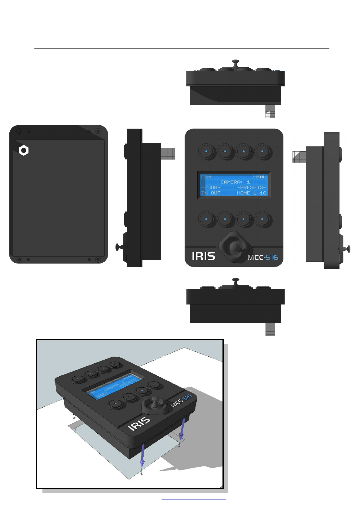
Installation Instructions
Page 6
V
ersion
1.00.
February
2013.
©Iris
Innovations
Limited.
www
.boat
-
cameras.com
. info@boat
-
cameras.com
6/21
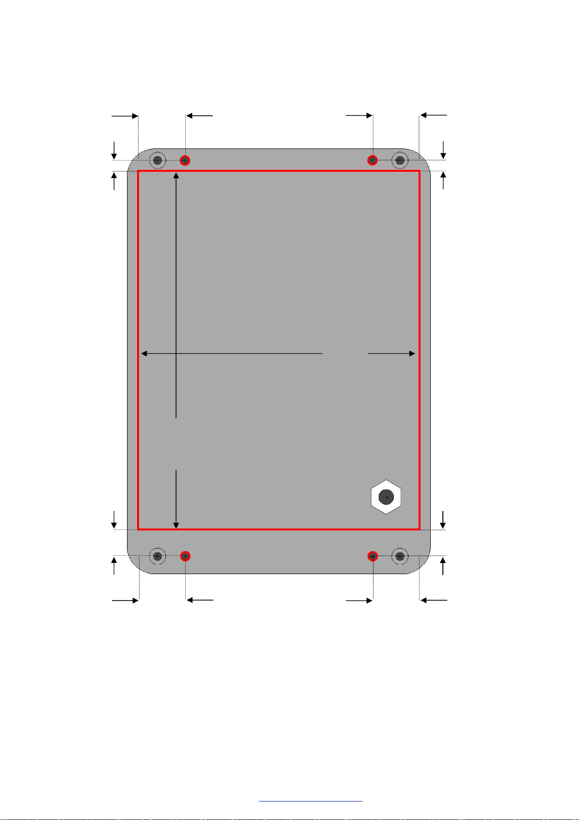
This Page is A4 scaled
The IRIS516 is designed to be panel mounted into a suitable dashboard or helm.
4 mm
17 mm
17 mm
4 mm
102 mm
130.5 mm
9.5 mm
9.5 mm
17 mm
17 mm
Fixing Points:
The 516 Controller is mounted using the supplied M3 machine screws.
Please use the red-marked areas on the template above as a guide to aid installation on
to the helm or console, using suitable cutting tools and a 3.5mm drill bit for the mounting
holes.
Page 7

V
ersion
1.00.
February
2013.
©Iris
Innovations
Limited.
www
.boat
-
cameras.com
. info@boat
-
cameras.com
7/21
Power and Data Connections
The fitted power and data cable is provided with bare ends to aid in installation, so please
ensure that care is taken in identifying the relevant connections and polarity.
Data communications to cameras and other devices is achieved via a two wire RS485
connection, and the data connection pins on the controlled devices will be labelled
appropriately with a “+” (positive) and a “–“ (negative) indicator.
Combinations of multiple control devices and multiple cameras may be connected together
using and Iris Data Expander.
Power your unit from a dedicated fuse / breaker rated at 12VDC / 500mA. The unit
operates when power to the breaker / fuse is applied. Ensure suitably rated cable is used
to handle the required current and voltage.
Connections from the cable:
Colour Function
Red 12v DC power
Black 0V DC / Ground
Green RS485 Data +
White RS485 Data -
Page 8
V
ersion
1.00.
February
2013.
©Iris
Innovations
Limited.
www
.boat
-
cameras.com
. info@boat
-
cameras.com
8/21
Operation:
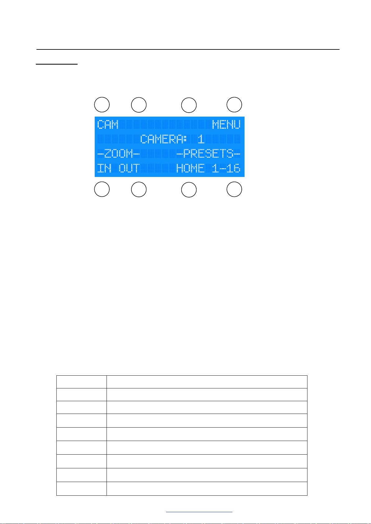
Main Menu:-
Immediately from power up the unit displays the Main Menu shown
1
5
2
6
3 4
7
8
below:
The currently selected camera is displayed in the centre of the LCD.
The eight tactile illuminated push buttons surrounding the display will action the function
displayed adjacent to each button
For example, on the main menu, button five (in the lower left corner of the unit) will perform a
zoom in function of the selected camera if available.
The push buttons are used to perform specific camera functions, and to navigate through the
menu structure.
From the Main Menu, movement of the joystick control will also pan and tilt any PTZ camera
connected and selected.
You can return to this Main Menu from any other menu, by pressing up on the joystick control,
unless specifically other-wise stated.
Pleas note that accessible features displayed on the menus will be dependant on the features
available of the currently selected camera, as not all cameras support the same feature set (ie
colour cameras will not be able to use thermal imaging capability).
On this Main Menu, the buttons and their relevant functions are:
Button Function
1 Navigate to Camera Select Menu
2 N/A
3 N/A
4 Navigate to the Function Menu
5 Zoom In
6 Zoom Out
7 Sent PTZ camera to Home position
8 Navigate to Preset Select Menu
Page 9

V
ersion
1.00.
February
2013.
©Iris
Innovations
Limited.
www
.boat
-
cameras.com
. info@boat
-
cameras.com
9/21
Camera Select Menu:-
Button Function
1-8 Select Camera to control
Camera Select:
This feature is used to change the currently controlled camera. The camera number
refers to the Pelco-D based address setting of the camera. Please see individual camera
installation documentation for instructions on how to set this.
Moving the joystick left and right will toggle between selecting cameras 1-8 and 9-16.
Preset Select Menu:-
Button Function
1-8 Select Preset to send camera to
Preset
positions.
Moving the joystick left and right will toggle between selecting presets 1-8 and 9-16.
Select:
This feature is used to send the currently selected camera to the save preset
Page 10

V
ersion
1.00.
February
2013.
©Iris
Innovations
Limited.
www
.boat
-
cameras.com
. info@boat
-
cameras.com
10/21
Function
Pause
:
Select Menu:-
Button Function
1 Navigate to Lens Function Menu
2 Navigate to Day/Night Function Menu
3 N/A
4 Toggles Image Pause
5 Navigate to Scan Modes Menu
6 Navigate to Thermal Scene Modes Menu
7 Navigate to Thermal Colour Palettes Menu
8 Navigate to Settings Menu
This feature will pause/freeze the image from the camera for further inspection, and
a second press will return the camera to a live video signal.
Page 11

V
ersion
1.00.
February
2013.
©Iris
Innovations
Limited.
www
.boat
-
cameras.com
. info@boat
-
cameras.com
11/21
Lens Function
Button Function
Wiper
:
Select Menu
:-
1 Wiper On Function
2 Wiper Off Function
3 Defogger On Function
4 Defogger Off Function
5 N/A
6 N/A
7 N/A
8 N/A
This feature enables/disables a camera lens wiper, if fitted, in order to clear the
display of any moisture. Ensure that any wiper is not enabled and continues to run whilst
the camera window is dry.
Defogger
short period of time and remove any condensation that has formed out the outside as a
result of temperature and weather conditions. If the camera does not have an automatic
time-out, please ensure the defogger is disabled once the screen is clear.
:
This feature enables a defogging unit which will heat the camera lens window for a
Page 12

V
ersion
1.00.
February
2013.
©Iris
Innovations
Limited.
www
.boat
-
cameras.com
. info@boat
-
cameras.com
12/21
Day / Night Functions
Button Function
1 Toggle Day/Night Mode / Set Day Mode
2 Set Night Mode
3 N/A
4 Set Day/Night Auto Mode
5 All Lamps Off
6 High (Spot) Beams on only
7 Low (Flood) lamps on only
8 All Lamps On
Day/Night
:
Menu
:-
This feature either sets the camera into Day mode (full colour) or Night mode
(monochrome with enhanced image clarity), or toggle between the two, dependant on the
camera model. The Auto option will set the camera to automatically detect the optimum
setting based on the current surrounding light levels. Ie. will automatically switch to Night
mode when dark, and back to Day mode when sufficient light is available to produce a
clear image again.
Lamps:
This enables either White-light flood lamps, or Infra-red beams if available on the
currently selected camera.
If fitted, available options will be to activate either high or low beams, for spot lighting and
flood lighting respectively, or to enable both simultaneously for maximum al-round night
vision, or to de-activate all lamps.
Page 13

V
ersion
1.00.
February
2013.
©Iris
Innovations
Limited.
www
.boat
-
cameras.com
. info@boat
-
cameras.com
13/21
Scan Functions
Button Function
1 Start 45° Scan / Start 360° Random Scan
2 Start 90° Scan
3 Start 180° Scan
4 Start 360° Continuous Scan
5 Stop Scan
6 N/A
7 Reduce Scan speed
8 Increase Scan speed / Start Auto-Cruise
Scans:
Menu
:-
The 45/90/180/360 degree scans will initiate the camera to begin automatically
moving back and forth in a sweeping motion to covering the respective angle around its
current position.
Speeds:
If the current camera supports variable speed scans, using the +/- Speed Set
button, then selecting the required scan will start the scan mode of at either speed 1 (slow),
2 (medium) or 3 (high speed).
Cruise:
Auto Cruise facility enables a camera to continuously go to each of it’s previously
configured preset positions in turn.
Stop:
The stop scan button if available will stop the current scan running and return to
normal operation. If this feature is not available, the camera will be returned to standard
control by panning or tilting the camera with the control joystick.
Page 14
V
ersion
1.00.
February
2013.
©Iris
Innovations
Limited.
www
.boat
-
cameras.com
. info@boat
-
cameras.com
14/21
Thermal Functions:-
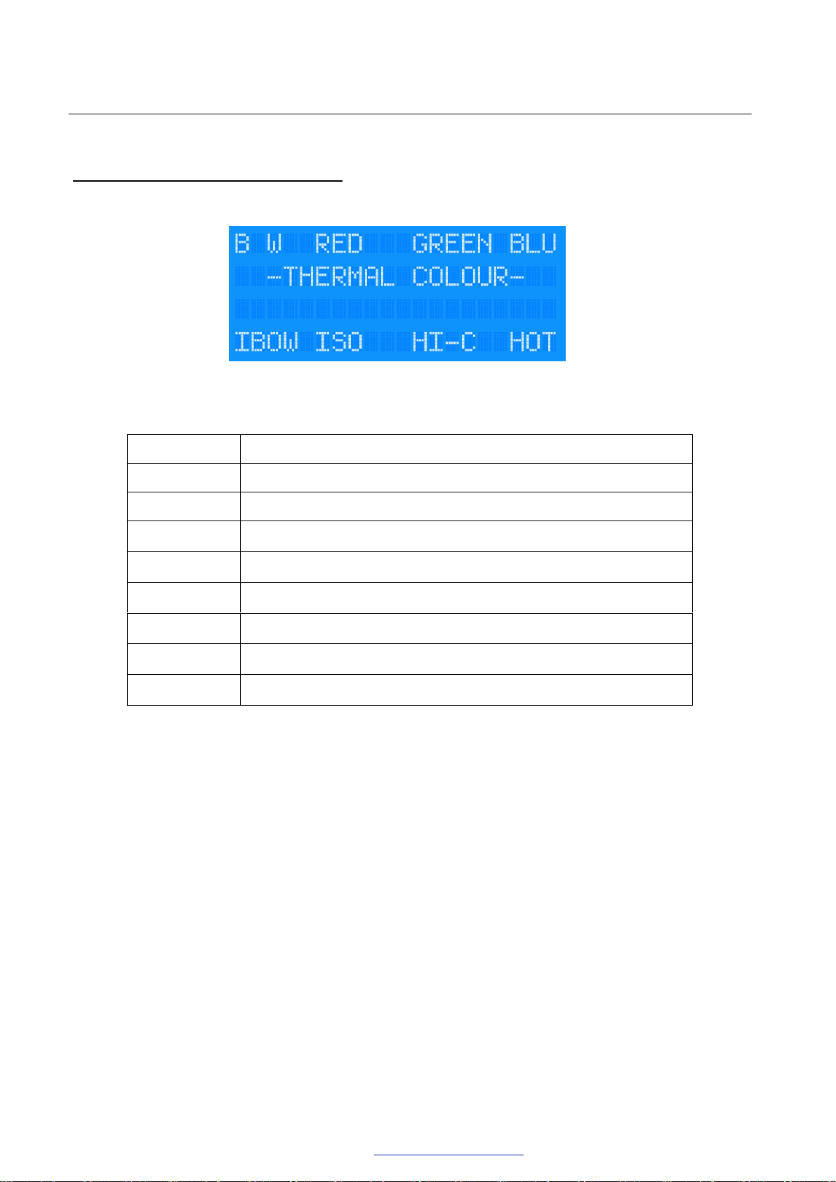
Thermal Colour Palette Selection:
Button Function
1 Set Black and White / Monochrome colour palette
2 Set Red-Black colour palette
3 Set Green-Black colour palette
4 Set Blue-Black colour palette
5 Set Iron-Bow colour palette
6 Set Iso-Therm colour palette
7 Set High Contrast colour palette
8 Set “Hot-Metal” colour palette
Palettes:
(ie. Iris 216/316).If the same button is pressed a second time, the colour palette will invert.
Eg. Pressing Red will display higher temperature regions in Red and lower temperatures in
black, and a subsequent press will display higher temperatures in black and lower
temperatures in Red.
These functions will set the displayed colour palette of a thermal imaging camera
Page 15

V
ersion
1.00.
February
2013.
©Iris
Innovations
Limited.
www
.boat
-
cameras.com
. info@boat
-
cameras.com
15/21
Thermal Scene Modes Selection:
Button Function
1 Set Day Mode
2 N/A
3 Set Fog Mode
4 Set Man-Over-Board Mode
5 Set Night Mode
6 N/A
7 Set Marina Mode
8 N/A
Thermal Modes:
operate in a specific mode. The modes available are exclusive to the IRIS216 and IRIS316
Thermal PTZ cameras, and are optimised to produce the best image possible in a
multitude of atmospheric conditions.
Please refer to the camera documentation for more details.
These functions will set an attached and selected Thermal imaging camera to
Page 16

V
ersion
1.00.
February
2013.
©Iris
Innovations
Limited.
www
.boat
-
cameras.com
. info@boat
-
cameras.com
16/21
Settings:
:-
Main Settings Menu:
Button Function
1 Navigate to Image Flip Menu / Flip Image
2 N/A
3 N/A
4 Navigate to Set Presets Menu
Image Flip:
The Image Flip function will either flip the image Vertically to allow inverted
mounting of each camera, or present the user with an additional menu if the camera
supports advanced image flip modes.
Home:
This will set the cameras current pan and tilt position as it’s new “Home” position. The
home position of a PTZ camera, is the position to which it will move when first powered up.
Please see relevant camera specific documentation for more details.
5 Navigate to Set Video Format Menu
6 N/A
7 Navigate to Set Camera Type Menu
8 Set Home Position
Page 17

V
ersion
1.00.
February
2013.
©Iris
Innovations
Limited.
www
.boat
-
cameras.com
. info@boat
-
cameras.com
17/21
Image Flip Menu:
Button Function
1 Flip Image Up / Standard
2 N/A
3 N/A
4 Flip Image Up / Mirrored
5 Flip Image Down / Standard
6 N/A
7 N/A
Image Flip:
If advanced image flip modes are available for the selected camera, the camera
image can be flipped in any combination of Up/Down/Standard and Mirrored.
Up/.Down:
Flip Up refers to when the PTZ camera is mounted with it’s base at it’s lowest point,
ie. deck mounted.
8 Flip Image Down / Mirrored
a ceiling or mast.
This will invert the image vertically to reflect it’s current mounting position.
Standard/Mirrored:
actual vieweing area accurately.
Eg. This is ideal for cameras mounted aft in order to aid reference. If the image is flipped
Mirrored, then whilst looking fore, Items on the users right of of the camera, will in fact be
shown on the right hand side of the display area, but would otherwise show on the left.
Similarly Flip Down refers to when the camera is mounted in a hanging position from
Flip Standard indicates that the camera is to display a standard image to reflect the
Flip Mirrored will provide a Horizontally inverted image.
Page 18

V
ersion
1.00.
February
2013.
©Iris
Innovations
Limited.
www
.boat
-
cameras.com
. info@boat
-
cameras.com
18/21
Preset Save Menu:
Button Function
1-8 Select Preset position to store
Preset
number for future use. From the Main Menu, navigate to the desired position using the
joystick control and zoom buttons first, and then via this menu that position can be saved
for future recall from the Preset Select Menu.
Moving the joystick left and right will toggle between the options for saving preset positions
1-8 and 9-16.
Set
Save:
This feature is used to save the currently camera position to the selected preset
Video Standard Menu:
Button Function
1 Set PAL video standard
Video Standard:
This menu allows the Video output standard to be changed from PAL to NTSC to
match that of the video display equipment. Some cameras will need to be power-cycled for
the change to take effect.
4 Set NTSC video standard
Page 19

V
ersion
1.00.
February
2013.
©Iris
Innovations
Limited.
www
.boat
-
cameras.com
. info@boat
-
cameras.com
19/21
Set
Camera Type Menu:
Button Function
1 Set as IRIS116 PTZ camera
2 Set as IRIS117 or IRIS118 PTZ camera
3 N/A
4 Set as IRIS216 or IRIS316 Thermal PTZ camera
Camera type / model:
This menu allows configuration of the IRIS516 controller for each connected
camera.
5 Set as IRIS106 PTZ dome camera
6 N/A
7 N/A
8 Set as IRIS130 PTZ camera
must be selected from the Camera Selection Menu, and then via this Set Camera Type
Menu, the correct model must be set for the relevant camera. This must be performed for
each camera connected on the system in order for the camera specific advanced features
to be accessible.
In order to enable the correct functionality for all connected cameras, first a camera
Page 20

V
ersion
1.00.
February
2013.
©Iris
Innovations
Limited.
www
.boat
-
cameras.com
. info@boat
-
cameras.com
20/21
Notes
Page 21

V
ersion
1.00.
February
2013.
©Iris
Innovations
Limited.
www
.boat
-
cameras.com
. info@boat
-
cameras.com
21/21
Iris Innovations Limited
Units 8
& 9 Swanwick Business Centre Bridge
Road
Swanwick
Hampshire SO31 7
GB
United Kingdom
Tel: +44(0)1489 570797 email:
info@boat-cameras.com
www.bo
at-cameras.com
 Loading...