

Page 1

IRIS106 MINI PTZ CAMERA
USER GUIDE & INSTALLATION MANUAL
IRIS INNOVATIONS LIMITED
Units 8 & 9 Swanwick Business Centre, Bridge Road, Swanwick,
Hampshire SO31 7GB. UK
IRIS INNOVATIONS USA CORPORATION
1535 SE 17TH Street, Suite 115, FT. Lauderdale, FL33316
www.boat-cameras.com
USA
Page 2

Warnings & Regulatory Information
Do not use harsh chemicals or cleaning solvents to clean the device.
Do not attempt to dismantle the device.
Unauthorized modifications or attachments could damage the device and may
violate regulations governing radio devices.
Any modification to the products cable tail may invalidate the product warranty.
Please contact Iris Innovations before attempting any modification to the cable.
Avoid dropping, knocking or excessively shaking the device. Rough handling
can break internal circuit boards and fine mechanics.
Observe correct polarity when connecting the power and data. Failure to do so
could result in damage to the unit.
This symbol on the product or its packaging indicates that it must not
be disposed of with your other household waste. Instead, it is your responsibility to dispose of your waste equipment by handing it over to a
designated collection point for the recycling of waste electrical and electronic equipment.
This device has been tested and found to comply with the limits for a
Class B digital device, pursuant to Part 15 of the FCC rules. These limits are designated to provide reasonable protection against harmful
interference in a residential installation. This equipment generates, uses
and can radiate radio frequency energy and, if not installed and used in
accordance with the instructions, may cause harmful interference to
radio or television reception.
We hereby declare that the product is in compliance with the essential
requirements and other relevant provisions of European Directive 1995/
5/EC (Radio and Telecommunications terminal equipment directive).
Iris Innovations: IRIS106 User Guide. v1.00 072013
Page 3

Introduction
The IRIS106 is a fully controllable Pan, Tilt and Zoom CCTV camera with low
light operation, designed specifically for use on boats as a security safety and
situational awareness aid.
The Camera is designed to be a small and low-profile as possible so that it
doesn’t protrude too much from head linings and so that it blends into the
aesthetic of the vessel. It’s marine grade stainless steel bezel features a high
polish finish and the mirrored dome provides enhanced privacy.
Key features include:
• Sony High Resolution Camera Module - 700TVL
• 10x Optical Zoom
• 10x Digital Zoom
• High Speed Pan and Tilt
• Proportional Control
• Auto Focus
• Automatic Day / Night Filter switches from colour during the day, to
monochrome at night or in low light for enhanced image clarity
• Built-in Fan to reduce condensation in hot environments
• Compact 3” Mirror Dome
• Marine Grade 316 Stainless Steel Bezel
• IP66 Water Resistant
• RS485 Communication / Pelco D Protocol
Page 4

Installation
To install the IRIS106 you will need the following tools:
• Drill with 105mm Hole Saw
• Drill Bit for Pilot Holes (2mm)
• Cross Headed Screw Driver
• Hand tools for connecting cables (unless pre-made cables are being
used), including wire cutters, wire stripper.
• Appropriate tool for terminating BNC connector (unless pre-made
cables are being used), such as knife to remove coax cable outer
sheath and dielectric, BNC Crimp Tool, Cable Insulation Stripper.
• Marine Sealant
Before you begin the installation, please take time to consider the
following important points:
• Always wear safety goggles, dust mask and ear protection when
drilling, cutting or sanding. Where suitable gloves when handling fibre
glass and GRP.
• Before drilling or cutting always ensure there are no obstructions,
cables or equipment on the opposite side of the surface you're working
on. Also ensure there is sufficient space behind the surface to
accommodate the body of the camera, and cabling and ensure you can
get the necessary cables to the camera position.
• Observe safe working procedures when working with electricity. Do not
connect the equipment to live power sources until correct, safe
termination through an appropriately rated fuse or breaker is made. Do
not attempt to install this product unless you are a certified electrical
installer. Failure to do so could result in injury or death.
• It is advised that before the equipment is fixed down, check that
desired viewing angles can be achieved in the intended installation
position, and that the equipment will not obstruct other equipment or
fixtures in it's intended position (such as doors or walkways for
Iris Innovations: IRIS106 User Guide. v1.00 072013
Page 5
example). If possible, power the item up and offer the camera up in the
vicinity of the desired installation position to double check suitability.
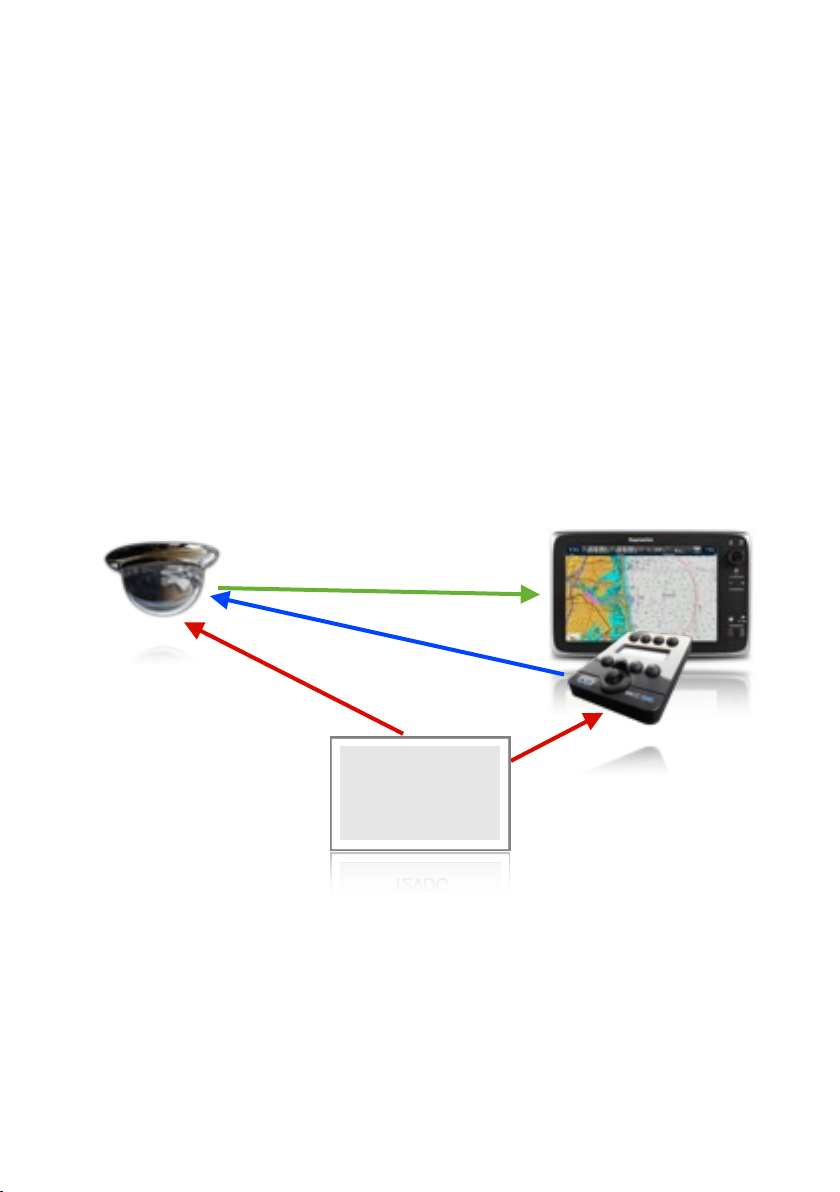
Cabling:
The camera has a 30cm cable tail which has a 2.5mm DC Barrel Jack (female)
to connect power, bare stripped and tinned wires (colour coded red and black)
for the RS485 serial control data) and a 75Ω BNC (female) connector for the
video signal, therefore it will be almost inevitable that the power, data and video
cables will need to be extended. In a typical installation, the video cable will
need to be routed back to the monitor (or chart plotter), the data pair will need
to be routed back to the controller or RS485 Data Distributor in larger installations and the power pair will need to be routed back to the boats distribution
panel. See the illustration below:
Composite Video 75Ω 1V P~P
RS485 Serial Data (Pelco D Protocol
12VDC Power
Power
Distribution Panel
12VDC Power
12VDC
Fig:1.0. Very Basic Installation. Single camera being controller by single
IRIS516 controller and video displayed on MFD.
Iris Innovations: IRIS106 User Guide. v1.00 072013
Page 6

RS485 Serial
Data Distributor
IRISEXP0204
Fig:2.0. Slightly more complex set up with 4 IRIS106 cameras being
controlled and viewed at 2 separate helm positions. Data from each
controller is fed into the input of the RS485 Serial Data Expander, and
data to each camera is connected to the outputs. This keeps the data
‘clean’ and prevents data cross talk and over-runs. Video from each
camera is fed into a VDA (Video Distribution Amplifier), which feeds two
MFD’s. Power not shown to keep diagram simple.
Video Distribution
Amplifier
IRISVDA0208
Page 7

Cabling (continued...)
The following cable specifications apply:
Video: 75Ω Coaxial Cable such as RG59, URM70, RG174 Mini-Coax.
Data: Single Twisted Pair
Power: 2 core. Rated 12VDC - max Current 1A
Individual cables can be run for each of the above, or 'Combination' (Combi)
cables can be used. Iris Innovations supply pre-made cables to length. Please
contact Iris for more details.
Camera Setup:
Before you can control the camera you need to ensure the cameras protocol
details and physical address are correctly set.
By default, the camera leaves the factory set up as follows:
Camera Address: 1
Camera Protocol: Pelco D
Baud Rate: 9600
Iris strongly recommend that the protocol and baud rate are not changed. The
IRIS516 controller will only control the camera with Pelco-D protocol and at
9600 baud.
You may however be required to change the address of the device. Each
camera must have it’s own unique address so that it only responds to
commands destined for it.
Camera Address:
To change the cameras address, remove the panel on the base of the unit and
select the desired address using the DIP switches on bank 2. Bank 2 has 8
switches which are used to select to binary address. A camera address table is
included at the end of this document. Do not alter the settings of the DIP
switches on switch bank 1.
Page 8
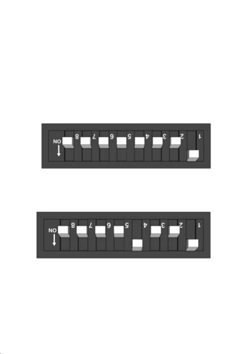
Camera Address (continued...)
The example below (Fig 3.0) shows the camera address set to 1, as switch 1 is
set to the ON position as shown by the arrow. As the switches set the binary
address, to set the cameras address to 2, set switch 1 to OFF and switch 2 to
ON. To set the camera to address 3, ensure both switches 1 and 2 are set to
the ON position. For address 4, switches 1 and 2 should be OFF and switch 3
should be ON. The value of each switch doubles. The value of each individual
switch is listed below:
Switch 1 = 1. Switch 2 = 2. Switch 3 = 4. Switch 4 = 8. Switch 5 = 16. Switch
6 = 32. Switch 7 = 64. Switch 8 = 128
Fig.3.0: Example of Camera Address set to 1
Fig.3.1: Example of Camera Address set to 9. Switch 1 has a value of 1 and
switch 4 has a value of 8, therefore 1 + 8 = 9
Iris Innovations: IRIS106 User Guide. v1.00 072013
Page 9

Fitting the Camera:
Step 1: After you have established the desired mounting position and are
happy there are no obstacles behind the surface into which you are drilling, use
a 105mm hole saw to carefully create the circular recess into which the camera
body will sit.
Step 2: Once the mounting hole has been cut offer the camera into place and
mark off the 4 fixing holes. Remove the camera carefully and use the 2mm drill
bit to create 4 pilot holes. Now, once the cables have been run and connected
up, re-insert the camera body into the recess and line up the four fixing holes
with the pilot holes. Fix the camera in place with the four self tapping screws
supplied. It is recommended that a marine grade sealant is used to add a bead
of sealant behind the flange so that a seal is formed when the camera is
screwed into place.
Step 3: Power up the camera to test operation. Upon power-up, the camera
will perform a short initialization routine whereby it will pan and tilt to find it’s
limits. On your screen will be listed the cameras physical address, protocol and
baud rate and show the status of each initialization test. This should last for
around thirty seconds whereafter the cameras video will be displayed and you
should now be able to control the camera.
Step 4: Now carefully screw the bezel into position. Care should be taken to
avoid cross threading the bezel at this stage and it is vital that the bezel is
tightly screwed into position.
Iris Innovations: IRIS106 User Guide. v1.00 072013
Page 10

Operation
Now the camera is installed, powered up from a suitably rated and protected
12VDC power source and the video is hooked up to the monitoring (or
switching / recording / routing ) equipment, the camera can be controlled using
any controller, MFD or interface that supports the widely available Pelco D
protocol.
Panning:
The camera pans through 360˚ continuously. Simply move the controller in the
desired direction of travel.
Tilting:
The camera tilts through 180˚ with an automatic ‘Auto-Flip’ feature so that the
camera image is automatically flipped when the camera reaches its tilt appex
(ie, points directly downwards) in order to correct the video orientation.
Zoom:
The camera features 10x optical zoom (F=4.9mm ~ 49mm). When the camera
reaches the extent of it’s optical zoom range it will automatically switch to
digital zoom. With digital zoom, each pixel that makes up the image is
multiplied in size in order to increase the overall image size.
Focus:
By default, the camera is set to Autofocus.
Preset Positions:
The camera features 256 user definable ‘memory’ locations, known as Presets.
These can be used to save physical pan/tilt positions into memory and recalled
Iris Innovations: IRIS106 User Guide. v1.00 072013
Page 11

at the touch of a button. Refer to the documentation of the controller for details
on how to save and recall preset positions.
OSD Menu (Extended Features)
The camera features many extended features and settings that are accessed
via an On Screen Display (OSD) menu. OSD Menu functionality may or maynot
be supported depending on the control interface. The OSD Menu is accessed
by calling Preset 95. To exit the OSD menu call preset 56.
Navigating OSD Menu
• Menu items with <> symbols indicate a drop down menu
• To access sub-menu, press either Near Focus or move joystick Right
• To return to the previous menu select the BACK option
• Use the joystick to navigate through menu options
• Use UP and Down to change values
• To save changes use Iris OPEN. To un-save use Iris CLOSE
Important:
Changing certain values within the OSD menu can effect the control of the
camera and it’s functionality. It is greatly recommended that values within the
OSD are left as default. For more information contact Iris Innovations Technical
Support.
Iris Innovations: IRIS106 User Guide. v1.00 072013
Page 12

Camera Address Table
This table lists the DIP switch settings to set address 1 through 75.
For information on how to set addresses 76 through 254 please contact Iris Innovations Technical Support.
Page 13

Limited Warranty
This Iris Innovations product is warranted to be free from defects in materials or
workmanship for one year from the date of purchase. Within this period, Iris will,
at its sole option, repair or replace any components that fail in normal use. Such
repairs or replacement will be made at no charge to the customer for parts or
labour, provided that the customer shall be responsible for any transportation
cost. This warranty does not apply to: (i) cosmetic damage, such as scratches,
nicks and dents; (ii) consumable parts, such as batteries, unless product damage has occurred due to a defect in materials or workmanship; (iii) damage
caused by accident, abuse, misuse, water, flood, fire, or other acts of nature or
external causes; (iv) damage caused by service performed by anyone who is not
an authorized service provider of Iris; or (v) damage to a product that has been
modified or altered without the written permission of Iris. In addition, Iris reserves
the right to refuse warranty claims against products or services that are obtained
and/or used in contravention of the laws of any country. This product is intended
to be used only as an aid and must not be used for any purpose requiring precise measurement of direction, distance, location or topography. THE WARRANTIES AND REMEDIES CONTAINED HEREIN ARE EXCLUSIVE AND IN LIEU OF
ALL OTHER WARRANTIES EXPRESS, IMPLIED, OR STATUTORY, INCLUDING
ANY LIABILITY ARISING UNDER ANY WARRANTY OF MERCHANTABILITY OR
FITNESS FOR A PARTICULAR PURPOSE, STATUTORY OR OTHERWISE. THIS
WARRANTY GIVES YOU SPECIFIC LEGAL RIGHTS, WHICH MAY VARY FROM
STATE TO STATE. IN NO EVENT SHALL GARMIN BE LIABLE FOR ANY INCIDENTAL, SPECIAL, INDIRECT OR CONSEQUENTIAL DAMAGES, INCLUDING,
WITHOUT LIMITATION, DAMAGES FOR ANY TRAFFIC FINES OR CITATIONS,
WHETHER RESULTING FROM THE USE, MISUSE OR INABILITY TO USE THE
PRODUCT OR FROM DEFECTS IN THE PRODUCT. SOME STATES DO NOT
ALLOW THE EXCLUSION OF INCIDENTAL OR CONSEQUENTIAL DAMAGES,
SO THE ABOVE LIMITATIONS MAY NOT APPLY TO YOU. Iris retains the exclusive right to repair or replace (with a new or newly-overhauled replacement product) the device or software or offer a full refund of the purchase price at its sole
discretion. SUCH REMEDY SHALL BE YOUR SOLE AND EXCLUSIVE REMEDY
FOR ANY BREACH OF WARRANTY. To obtain warranty service, contact your
local Iris authorized dealer or call Iris Innovations Product Support for shipping
instructions and an RMA tracking number. Securely pack the device and a copy
of the original sales receipt, which is required as the proof of purchase for warranty repairs. Write the tracking number clearly on the outside of the package.
Send the device, freight charges prepaid, to any Iris Innovations warranty service
agent. An additional 12 month warranty restricted to the limitations listed above
is available free of charge by registering the product upon purchase via the Iris
Innovations website www.boat-cameras.com
Iris Innovations: IRIS106 User Guide. v1.00 072013
Page 14

Notes:
Iris Innovations: IRIS106 User Guide. v1.00 072013
Page 15

Notes:
Iris Innovations: IRIS106 User Guide. v1.00 072013
Page 16

Iris Innovations Limited
Units 8 & 9 Swanwick Business Centre
Bridge Road, Swanwick, Hampshire SO31 7GB
United Kingdom
Tel: +44(0)1489 570797
Iris Innovations USA Corporation
1535 SE 17th Street, Suite 115
Fort Lauderdale, Florida 33316
United States of America
Tel: +1 (954) 903 3666
info@boat-cameras.com
www.boat-cameras.com
 Loading...