

Page 1

IM-DND-80
Vari-Focal Water-Resistant Infra Red Dome Camera
USER GUIDE
Iris Innovations Limited
Unit 9 Swanwick Business Center
Bridge Road, Swanwick
Hampshire SO31 7GB. United Kingdom
T: +44(0)1489 570797 / F: +44(0)1489 875990
info@boat-cameras.com
www.boat-cameras.com
Rev:2.0 / 07/12/10
Page 2
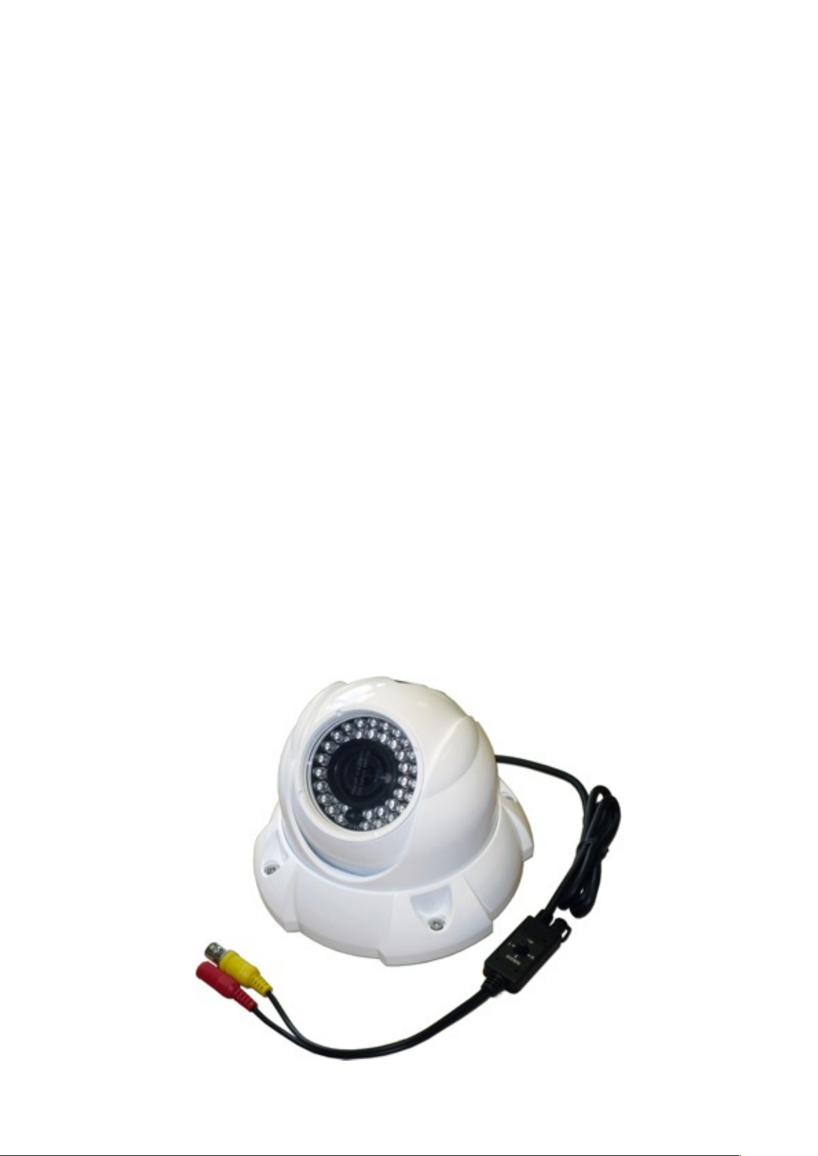
An Introduction to the IM-DND-80
Mid-Range Day/Night Infra Red Vari-Focal CCTV Camera,
with NEW Wide Dynamic Range Image Processing.
Description
The IM-DND-80 Vari-Focal Dome Camera from Iris Innovations is an extremely tough and
compact, waterproof, Day / Night CCTV camera for use in applications that are exposed to
harsh environments such as marine, outdoor etc and where there are extremes of contrast in
light levels. For marine environments where there is reflection from water, white-boats and metal
fixtures, the Wide Dynamic Range processing of the IM-DND-80 provides a superior image to
standard CCTV cameras.
Features
Extremely High Resolution - 600 TVL
Waterproof - IP66
Vari-Focal Lens - Adjustable 2.9mm~12mm.
Wide Dynamic Range - Provides superior images internally and externally under extreme light
conditions.
Digital Noise Reduction - Automatically reduces noise in low light conditions.
Digital Image Stabilization - Anti-Shake compensation against outside influences such as wind
and vibration.
High Sensitivity True Day / Night - Delivers high quality colour rendition and converts image to
monochrome as luminance levels drop.
40 x Infra Red LEDʼs - Provides up to 30 meters visibility at night in outdoor conditions.
Built-in On Screen Menu Functions for Extended Feature Set -
Mini in-line joystick controller to access the extended feature set within the camera. Features
include; Privacy Masking, Reverse Image, Digital Zoom (x1~x10) as well as all the other usual
camera features.
Page 3
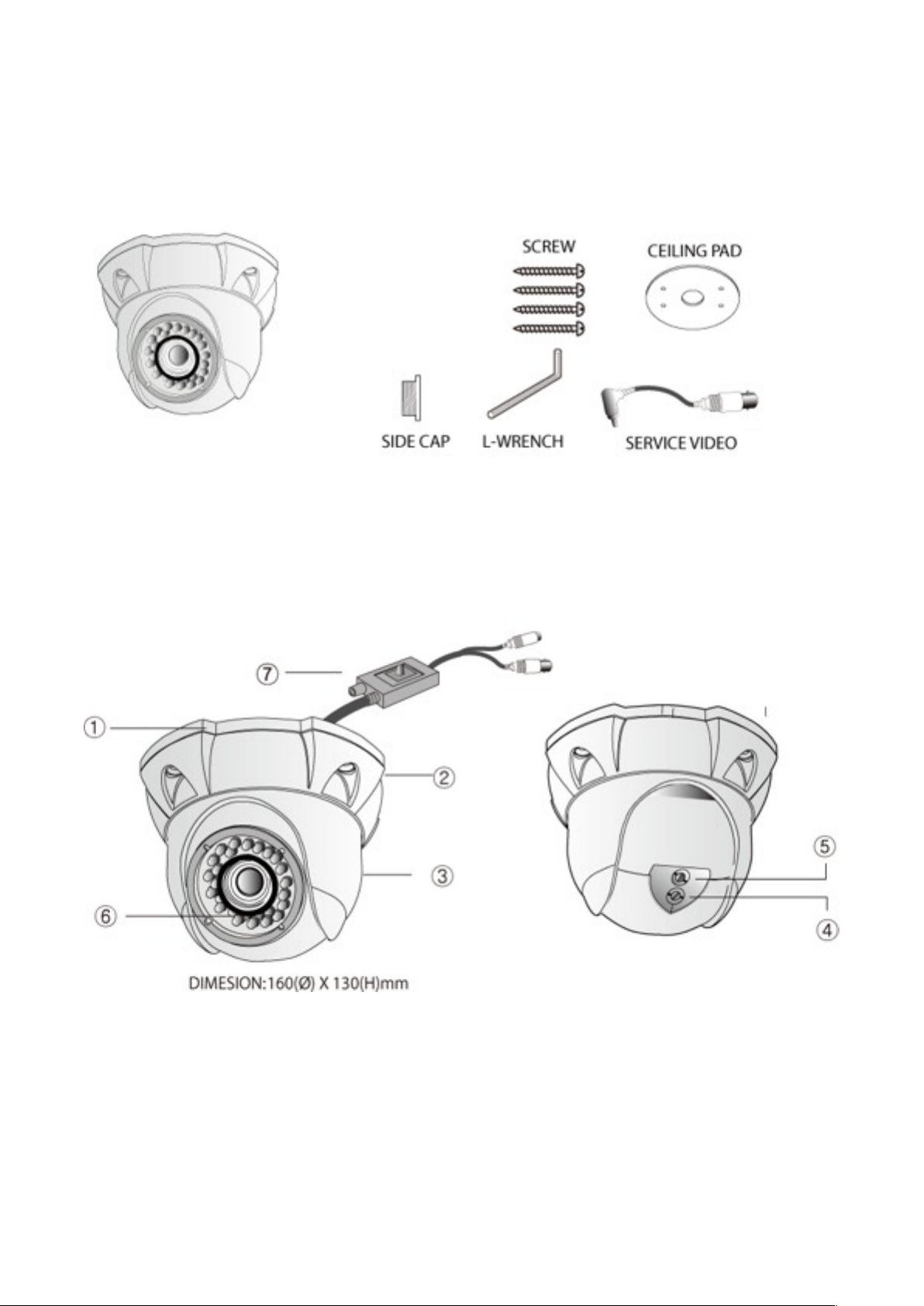
Carton Contents
Before commencing your installation please ensure all the correct components are present, as
listed below:
Description of Parts
Names and functions of parts and components:
1. Camera Base
2. Dome Cover Ring
3. Dome Cover
4. Focus Pot
5. Zoom Pot
6. 40 x IR LEDS
7. In-Line Control Unit
Page 4

Installation
Before you fix your IM-DND-80 into place we recommend you power up the camera and check
the video output to ensure the desired scene is achievable from the installation position.
Complete the installation only when you are happy you can see what you need to see!
Cable (VIDEO)
Use a suitable video cable such as RG59 / URM70 Coaxial with an impedance of 75Ω, or CAT5
cable if baluns are to be used to transmit the video system.
Cable (POWER)
Use suitably rated power cable to drive the camera. The supply voltage is rated at 12VDC ±
20% and the current consumption is 500mA maximum.
The camera cable tail has a built in joystick unit
for use during set-up. Please allow for this when
planning cable entry holes. Use a 20mm hole
cutter to facilitate the joystick controller.
The cable tail is fitted with a female 75Ω BNC
connector for the video signal and a 2.1mm DC
ʻBarrelʼ connector jack for the power supply.
These connectors have been specified as they
are both widely used and familiar components
and can easily be sourced and fitted. If desired
these connectors can be removed and replaced
with connectors of your choice. This will not
effect the warranty of the product unless
damage has been caused as a result of this
process or incorrect subsequent re-connection.
To install remove the hex screws that fix the
dome cover ring(2) in place and remove the
dome cover ring. Loosen the grub screws that
lock the dome cover(3) and remove dome
cover. Remove the camera dome from the
camera base(1) and offer the camera base(1)
into position to mark your fixing holes and cable
entry hole. Fix the camera base(1) into position
using fixings appropriate to the installation. Use
the rubber ceiling pad if desired to protect the
mounting surface. Now re-assemble the
camera.
It is advised that the fixing screws that retain the
camera dome and dome cover are tightened
only loosely until the camera is finally powered
up and adjusted accordingly. It is also advised
to carry out camera set-up before finally locking
everything into place.
Page 5
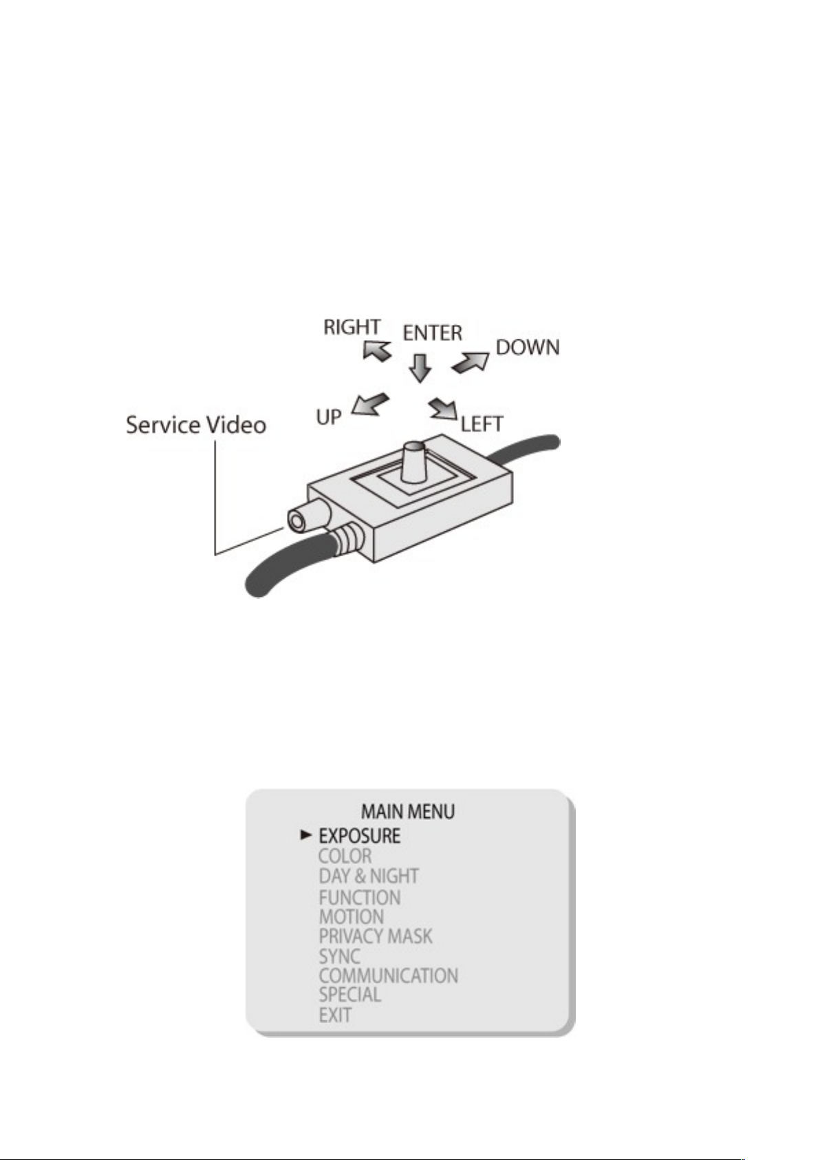
Setting Up your Camera
Setup should be carried out before the camera is finally locked into place unless it is possible for
the installer to gain access to the cable mounted joystick controller (pictured below) following
install.
The joystick controller has a separate service video input to connect a local monitor if
necessary, otherwise simply view the on screen menus from your system monitor or chart
plotter screen.
The joystick can be moved up, down, left and right through the menus and selections made by
pressing the joystick.
To access the on screen menus, press the joystick once.
Enter: Use to access the Main Menu and Sub Menus and return to the Main Menu.
UP / DOWN: Moves the cursor UP and/or Down to select a desired menu item.
LEFT / RIGHT: Use to select (change) or adjust the parameter value of the selected item.
Page 6

Setting Up Menu Flow
Use the joystick controller to navigate through the menus and make desired changes in
accordance with the menus and values detailed below:
Page 7

Specifications
Page 8

Installations should only be carried out by fully qualified service personnel and should
conform to all local codes.
Iris Innovations Limited
Unit 9 Swanwick Business Center
Bridge Road, Swanwick
Hampshire SO31 7GB. United Kingdom
T: +44(0)1489 570797 / F: +44(0)1489 875990
info@boat-cameras.com
www.boat-cameras.com
Dealer
Declaration of Conformity
Model Number: IM-DND-80-P / IM-DND-80-N
Trade Name: Iris Marine
Responsible Party: Iris Innovations Limited
Address: Unit 9 Swanwick Business Center,
Bridge Road, Swanwick, Hampshire SO31 7GB.
United Kingdom.
Telephone: +44(0)1489 570797
This device complies with Part 15 of the FCC Rules. Operation is subject to
the following: (1) this device may cause harmful interference, and (2) this
device must accept any interference received including interference that may
cause undesired operation.
 Loading...