

Page 1
USE AND
MAINTENANCE
INSTRUCTIONS
REV No. REVISION DESCRIPTION REV. DATE PROOF READER
00 26/10/2015 L.B.
01 10/09/2017 D.N.
FIRST EMISSION
ADDED GAS R452A
Page 2

Dear Customer,
Thank you for having chosen IRINOX.
Please take the time to read this manual carefully to make the most of all the potential and benefits of your
new CP ONE.
We would like to remind you that the perfect operation of the machine also depends on its correct use.
Keep this manual close to the CP ONE so that it can be consulted easily by you and anyone else.
The graphic representations of the controls in the manual have been designed to make the machine easy
and intuitive to use.
Symbols key
suggestions and details for correct use of the blast chiller
standards for your safety
additional information in the manual
Information regarding the warranty and assistance
Warranty validity: of the individual parts for 12 months from the date of invoicing, as stated in the price list in force.
Contacts:
Customer service: +39.0438.5844
User assistance +39.0438.5844
Technical - spare parts after-sales +39.0438.2020
Fax +39.0438.2023
E-mail service@irinox.com
Web site www.irinoxprofessional.com
For every request relative to your product, always indicate:
• The model
• The serial number
stated on the label on the machine.
Page 3
SAFETY INFORMATION
Below are the main general Safety
Standards:
do not touch the machine with humid or wet
•
hands or feet
do not work on the machine with bare feet
•
do not insert screwdrivers, kitchen tools or
•
any other object between the protections and
moving parts
before performing any cleaning or routine
•
maintenance operation, disconnect the
machine from the electrical power supply by
turning the main switch off and removing the
plug
do not pull the power supply cable to discon-
•
nect the machine from the power supply
mains.
If the power supply cable is damaged it
must be replaced by the manufacturer,
by a service centre, or by qualified staff in
order to avoid risks.
Non-mobile equipment, not equipped with
disconnection devices from the power supply
having a contact separation of all poles that
provides disconnection in category III overvoltage conditions, must be equipped with a
disconnection device incorporated in the fixed
connection in compliance with the connection
regulations.
Use gloves suitable for cold trays.
The responsibility of the operations
performed on the machine, ignoring
the indications stated in this manual, is implemented by the user.
Climatic class:
4 (environmental temperature 30°C with
relative humidity 55% non-condensing)
pursuant to Standards IEC EN 60335-1, IEC
EN 60335-2-89, ISO 23953-2:2005(E)
Do not store explosive substances such
as spray cans with flammable propellant
inside the appliance.
Children should be supervised to ensure
they do not play with the appliance.
Cleaning and maintenance by the user
should not be performed by children
without the supervision of an adult.
The machine is not intended for use in
a potentially explosive environment.
The manufacturer declines any liability
if this note is not complied with.
During cleaning operations, especially of
the condenser, always wear protective
gloves, glasses and masks for protection of
the respiratory tract.
It is prohibited to remove the protections
and safety devices in order to perform
routine maintenance.
Do not overload the machine beyond
that indicated by the manufacturer
(3.5.2. Loading the machine).
Maximum load per shelf: 10 kg
3
Page 4

INDEX
1. GENERAL DOCUMENTATION 5
1.1 GENERAL WARNINGS 5
1.2 INTRODUCTION 5
1.3 TRANSPORT AND HANDLING 5
1.4 UNPACKING AND DISPOSAL OF PACKAGING 6
2. INSTALLATION 7
2.1 PLATE DATA 7
2.2 POSITIONING 7
2.3 DIMENSIONAL DATA 8
2.4 ENVIRONMENTAL TEMPERATURES AND AIR EXCHANGE 9
2.5 COOLING CAPACITIES 9
2.6 ELECTRICAL CONNECTION 9
2.7 REFRIGERATOR CONNECTION 10
2.8 CONDENSATE DRAIN 11
2.9 WATER COOLING UNITS CONNECTION 11
2.10 NOTES FOR THE INSTALLER 12
2.11 SAFETY AND CONTROL SYSTEMS 12
2.12 R404A /R452A GAS SAFETY SHEET 13
2.13 DISPOSING OF THE MACHINE 14
3. OPERATION 15
3.1 USE 15
3.2 CONTROL PANEL 15
3.3 DESCRIPTION AND OPERATION 16
3.4 STOP MODES 19
3.5 RECOMMENDATIONS FOR USE 19
4. MAINTENANCE / ASSISTANCE 20
4.1 ROUTINE MAINTENANCE 20
4.2 CLEANING THE CELL 20
4.3 TROUBLESHOOTING 21
4.4 EXTRAORDINARY MAINTENANCE 23
4
Page 5
1. GENERAL DOCUMENTATION
1.1. GENERAL WARNINGS
This manual is an integral part of the product, it
•
supplies all of the indications necessary for correct
installation, correct use and maintenance of the
machine.
It is mandatory for the user to read this manual care-
•
fully and always make reference to it. Moreover, it
must be kept in a place that is known and accessible
to the authorised operators (installer, user, maintenance technician)
The holding cabinet is intended for professional use
•
and therefore only qualified staff can use it.
The holding cabinet is intended only for the use for
•
which it has been designed, i.e. for storage of food
products.
Products that require constant temperature control
•
and recording are excluded, such as:
1.2 INTRODUCTION
Installation must be carried out by authorised and
specialised staff, respecting the instructions in this
manual. The manufacturer declares and assigns to
each individual machine a Declaration of Conformity to
the 2006/42/EC Machinery Directive, to the 2006/95/EC
Low Voltage Directive and to the 2004/108/EC Electromagnetic Compatibility Directive.
Whenever the machine is supplied with the remote
condensing unit, it is the installer's responsibility to check
all connections and issue a declaration of perfect execution that is in compliance with the provisions of the abovementioned Directive. The joints made by IRINOX S.p.a.
are in compliance with Standard EN14276-2.
- heat reactive chemicals
- medicines
- blood products
The manufacturer declines any liability for any damage
•
caused by incorrect or unreasonable use, such as for
example:
- improper use by untrained staff.
- modifications or interventions that are not specific
for the model.
- use of non-original spare parts or that are not
specific for the model.
- failure to comply, even partial, with the instructions
in this manual.
IMPORTANT NOTE: IRINOX reminds you that all
machines must be subjected to periodic inspections in
compliance with the national standards in force.
In particular for the Italian market: a complete control of
the plant must be carried out and especially an inspection of the integrity of the cooling circuits under pressure after ten years of operation as a set, as required in
Italy by Annex B of the Italian Ministerial Decree no.
329 of 1 December 2004 for sets belonging to categories from I to IV containing group 2 fluids.
1.3 TRANSPORT AND HANDLING
All necessary precautions must be adopted when
•
handling the appliance in order not to damage it,
respecting the indications on the packaging.
Table 1
WEIGHT
Holding cabinet model
CP ONE
Condensing unit (if remote)
Condensing unit
NET
kg
240 840 2270 1190 2,27 275
38 690 450 720 0,22 58 700 450 780 0,25 76
(mm) H (mm) D (mm) m
L
CARDBOARD PACKAGING CRATE PACKAGING
3
kg
L (mm) H (mm) P (mm) m
930 2320 1230 2,65 410
5
3
kg
Page 6

1.4. UNPACKING
•
Remove the cardboard or wooden packaging or crate
from the wooden base on which the machine is
rested.
Lift the machine using suitable means (forklift truck),
remove the wooden base and position the machine in
the envisioned place (see par. 2.2).
•
After the packaging has been removed, check the
integrity of the holding cabinet.
•
Remove the protective PVC film from all sides (Fig.1).
•
•
When handling the packaging and the wooden
base, use protective gloves.
NOTE: all of the various packaging components must
be disposed of according to the Standards in force in
the Country where the appliance is used. In any case,
nothing must be dispersed into the environment.
Fig. 1
6
Page 7

2. INSTALLATION
2.1. PLATE DATA
•
Check that the plate data and the characteristics of
the electrical line correspond (V, kW, Hz, no. phases
and power available).
•
The plate showing the appliance's characteristics is
affixed on the right side of the holding cabinet (fig.2)
and under the control panel.
The eventual preparation of machine rooms for positioning
the condensing units must follow the Standards in force
in the country of installation regarding fire prevention
(contact the local fire department for the due indications).
It must also be considered that any intervention of
the safety valve or fuse caps, currently in the refrigerator
circuit, leads to the immediate discharge of all coolant
used in the environment. Consequently, realise
appropriate means of disposal and first aid as indicated
in the coolant safety sheet (8see par. 2.12).
Mod.
s/n
V
A
Compressor HERMETIC
Refrigerant R404A / R452A Charge
Desing pressure (Low)
Desing pressure (High)
Class Volume
Rated Load
IP
PED Code
Ph Hz
Fig. 2
31010
CORBANESE (TV)
ITALY
KPa
KPa
Model
Serial no.
mm/yy/progres.
Kw
Frequency
Power
Phase
Volt
Absorption
2.2. POSITIONING
•
The machine must be installed and inspected with
complete respect of the accident-prevention legal Standards, traditional regulations and Standards in force.
•
The installer must check any provisions on the subject
of fire prevention (contact the local fire department for
the due indications).
•
Place the machine in the provided place.
•
Use the adjustment feet to level the appliance. Do not
use the forklift truck to straighten the machine as it
could damage the basin guides on the bottom of the
machine (Fig.3).
If the appliances are not levelled, their functioning and
•
the flow of condensate can be compromised.
To avoid (Fig.4):
•
Places exposed to direct sunlight
•
Enclosed places with high temperatures and poor air
exchange. (
•
Do not install the machine near to any heat source.
see Table 2).
•
The remote units are designed to be installed in
places protected from the weather. The plants must
be positioned on a level cement or steel base and
space for maintenance must be foreseen, as indicated in the technical data sheets. For installation on
the roof or on floors, weight distribution beams should
be arranged. The base must also be sufficiently
strong and suitable to support the weight of the entire
unit, as resulting from the technical data on the specific drawing. To avoid additional vibrations and noises
we recommend use of neoprene anti-vibration mats
placed under the corners of the unit's base.
•
If the operating cabinet holder is to be installed below
the floor level or underground, the installer will apply
the clauses required by the Standard EN3781:2008+A1:2010 ANNEX D to ensure that no person
can remain locked in the cell at the end of the work
shift.
•
The cabinet holder can be installed underground or on
a mezzanine as long as there are suitable emergency
exits as provided for by the Standard EN3781:2008+A1:2010 ANNEX C.
Fig. 3
Fig. 4
•
The need for forced ventilation in a room where the
cabinet holder is installed must be verified by the
installer, as required by the Standard EN3782:2008+A1:2009 in chapter 6.2.14.
7
Page 8

2.3. DIMENSIONAL DATA
810
B
1970
2085
Service Area
250
B
AA
56
670
1053,5
SECTION
A-A
1347
871,5
SECTION
8
B-B
Page 9

2.4. ENVIRONMENTAL TEMPERATURES AND AIR EXCHANGE
For air-cooled chiller units, the temperature of the
operating environment must not exceed 30°C. The
performance declared is not guaranteed above this
temperature.
The remote condensing units must be installed in opposite rooms or outdoors, in a place protected from direct
sunlight. If the circumstances should make it necessary, the installer must evaluate whether the use of a
cover or roof is required (in all cases sufficient air
exchange must be guaranteed).
For further details
see Table 2.
2.5. COOLING CAPACITIES
Table 4
Cooling capacity [W] Condensing power [W]
1458
Values declared at T.evap=-10°C and T.cond.=40°C.
Over-heating in compliance with EN12900
2248
2.6. ELECTRICAL CONNECTION
Table 2
MINIMUM AIR EXCHANGE
3
m
/h AIR 700
Table 3
MAXIMUM WATER USE (when foreseen)
Well water (l/h)
Values referring to the condensing power declared at -10/40°C
in compliance with EN12900
220
Install an automatic differential circuit breaker switch
upstream from every appliance, for omnipolar disconnection of the power supply, according to the Standards
in force in the country of installation.
The dimensions of the connection cables must be in
compliance with the information contained in the electrical data on the technical data sheets. The voltage of
the systems must be within the limit of +10% and the
voltage distortion of the phases must not exceed 3%.
The electrical power connection must be performed by
qualified staff, in compliance with the directives and
laws in the country of installation. The power supply is
to be taken to the electrical control panel of each single
appliance, according to the data in
The electrical power supply cables must be correctly
•
Table 5.
sized for the units installed;
•
The electrical cables must be laid and blocked in the
relevant cable gland and installed properly according
to the place of installation;
Every wire must be inserted into the corresponding
•
terminal;
•
The earth wire must be correctly connected to an
efficient earthing system.
POWER SUPPLY
Voltage
220-240
Frequency
(V)
220
200
(Hz)
50
60
50/60
Poles
1P+N+PE
1P+N+PE
2P+PE
nominal
POWER SUPPLY
Power
(kW)
0,93
0,85
0,88
Power
(A)
5,2
4,5
5,6
defrosting
ABSORPTION
Potenza
(kW)
1,30
1,60
1,30
The manufacturer declines all liability and
every warranty obligation, whenever the appliance
or objects are damaged and persons are injured
due to incorrect installation and/or failure to
comply with the laws in force.
Fig. 6
Fig. 7
Table 5
POWER
SUPPLY CABLE
3G1,5mm2+3G2,5mm
3G1,5mm2+3G2,5mm
3G1,5mm2+3G2,5mm
Current
(A)
6,4
7,2
6,7
POWER
SUPPLY CABLE
Type Section Type Section
H07RN-F
H07RN-F
H07RN-F
3G1,5mm
3G1,5mm
3G1,5mm
2
H07RN-F
2
H07RN-F
2
H07RN-F
2
2
2
NOTES: cable sized for a length of 7m with an industrial voltage drop ∆V% ≤ 1%
9
Page 10

2.7. REFRIGERATOR CONNECTION
2.7.1. Equal level installation
General criteria that must be satisfied in the installation of
the remote units:
1)
Slope of the pipes (Fig.8)
Fastening brackets onto the insulated pipes.
2)
The number of brackets to be applied to the refrigerator connection line of the remote units
Table 6.
Hermetic sealing (Fig.10).
3)
Execution of the vacuum (0.03 mBar) in the connec-
4)
tion pipes (flow and intake).
5)
Check vacuum sealing of the pipes.
6)
Opening of the shut-off valves on the condensing
unit.
Leak check.
7)
8)
Check of the exact gas load via the liquid passage
indicator light on the condensing unit.
see
Fig. 8
Tabella 6
DISTANCE
Cell -> Remote unit
10 metres 3
15 metres 5
20 metres 7
25 metres 8
COMPRESSORE
2%
COMPRESSOR
NUMBER
OF BRACKETS
5 metres 2
Check of the circulation and pressure of the conden-
9)
sing water (systems with water cooling).
The criteria indicated above are sufficient for
installation at equal level (Fig.11).
The pipes must be installed so that their lengths may be
varied, using supports so they can slide and that provide sufficient space near to the walls and other obstructions.
If the cabinet holder's heat exchangers can be shut-off
from the rest of the plant via valves, these exchangers
must be protected by suitable safety devices as foreseen by the Standard EN378-2:2008+A1:2009 in chapter
6.2.6.8.
For water-cooled units or units with heat recovery: for
the choice and installation of the water pipes, the local
provisions and regulations regarding constructions and
the safety standards must be followed.
The installer must provide mechanical coupling of the
appropriately sized connections to the system and make
sure that the water inlet and outlet connections are
compliant with the dimensional drawing and with the
labels on the connections. The pipes must be supported
to reduce weight and strain on the connections. A filter
that can be inspected for filtering solid bodies must be
installed on the inlet pipe to the exchanger. If the noise
and vibrations are critical, anti-vibration joints must be
installed on the water inlet and outlet pipes from the
exchangers.
Fig. 9
Fig. 10
Equal level
installation
10
Fig. 11
Page 11
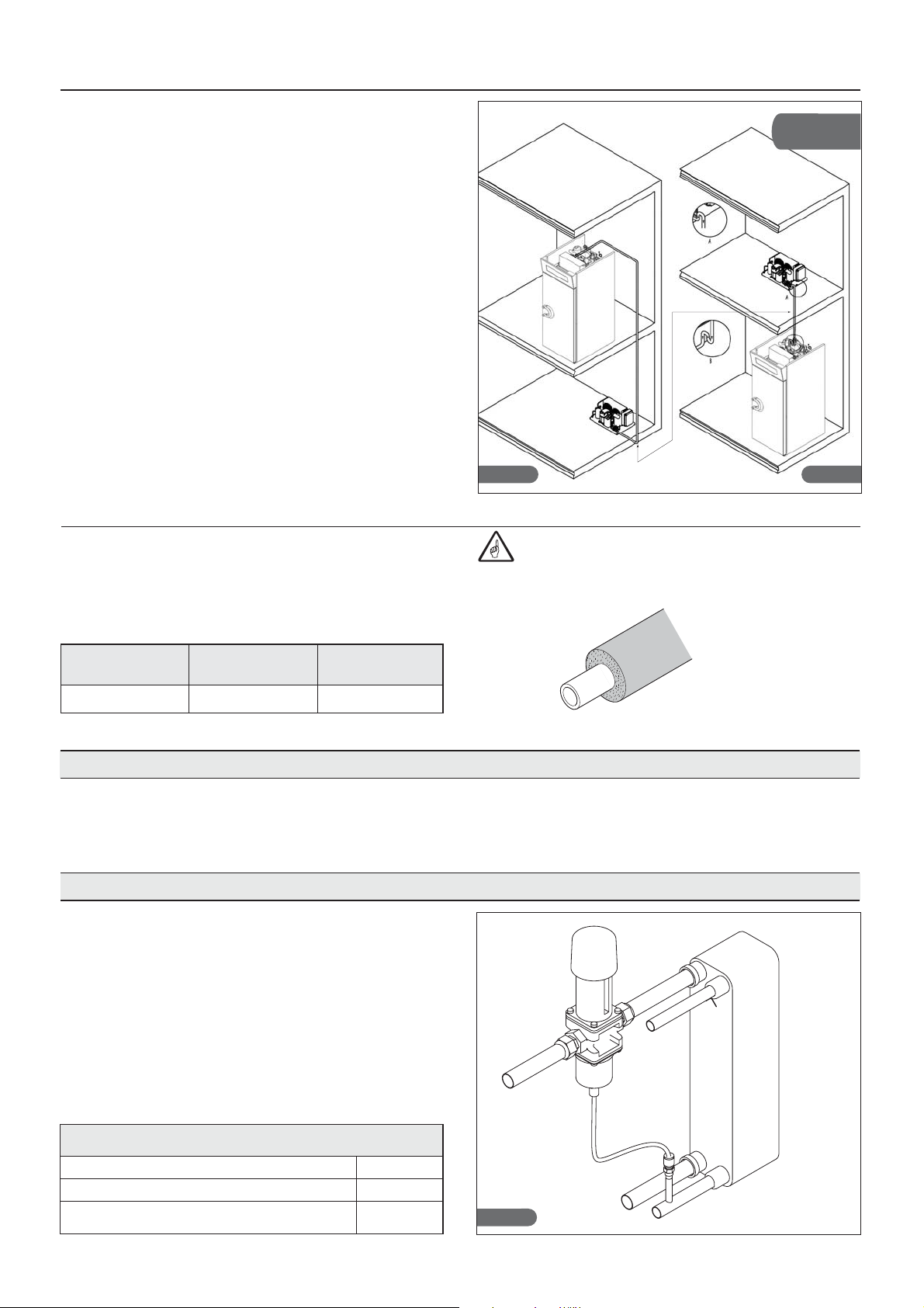
2.7.2. Different level installation
If the remote unit is installed higher with respect to the
appliance (fig.13), a siphon must be installed at every
branch or return (a), every 1.8 metres of difference in level
along the return pipe and at every delivery (b).
If the remote unit is installed lower compared to the appliance, no siphon is required (fig.12).
2.7.3. Refrigerator-remote units connection
The diameters of the appliance power supply pipes are
sized for installation distances up to 15 metres (see
Table 7).
For greater distances, contact IRINOX Spa.
Table 7
Flow line
Ø mm
61210
Pipes maximum length: 15 m
Intake line
Ø mm
Hot gas line
Ø mm
Dierent level
installation
Fig. 12 Fig. 13
L’isolamento della linea di aspirazione e del gas
Intake pipe
caldo dovrà essere fatto con isolante del tipo a cellule
chiuse di buona qualità, dello spessore minimo di 19
mm.
19 mm
2.8. CONDENSATE DRAIN
CP ONE has a basin for collecting the condensate.
The basin can be extracted from the bottom part of the
cabinet holder.
2.9. WATER COOLING UNITS CONNECTION
•
During testing (mains water), with the machine at a
standstill and water network ready, check that the
condenser drain pipe does not allow water to escape.
If this is not the case, regulate the pressure valve until
the leak stops (Fig.17).
•
It is recommended to supply a gate valve and an
inspectionable filter in the water flow line. The
condenser water flow and drain pipes are indicated by
relevant plates. Both connections are 3/8”F and threaded.
•
See Table 3 for maximum water consumption
FEATURES OF THE LINE FOR
WATER-COOLED CONDENSING UNITS
Maximum pressure of the inlet water
Minimum pressure of the inlet water
Maximum temperature of the inlet water in order to
guarantee normal functioning of the appliance
1600 KPa
50 KPa
25°C (well water)
Fig. 17
11
Page 12

2.10. NOTES FOR THE INSTALLER
Verification of correct installation and testing:
•
Check for any gas leaks from the seals or joints
made during the installation phase.
•
Check the good insulation of the connection pipes
between cabinet holder and remote condensing unit
(when foreseen).
•
Check the electrical connection.
•
Check absorption.
•
Check the standard pressures.
•
Check the water connection by regulating the pressure valve during operation and the good circulation of
the condensing water (when the holding cabinet is
water-cooled).
•
Perform at least one complete preservation cycle
(reach the set temperature), and one manual defrosting cycle.
Inform the customer regarding the exact use
of the appliance with specific reference to use and
the requirements of the customer him/herself.
Installation and the start-up must be performed by authorised staff.
2.11. SAFETY AND CONTROL SYSTEMS
•
Door micro switch (A): blocks operation of the fans in
the cell when the door is opened.
•
Protection fuses (B): protect the circuits from short
circuit and overloads.
•
Fuse holders (C): they contain the fuses and they
allow the opening and isolating of the circuits.
•
Electronic boards (D): depending on the parameters
acquired, they command and control the various
devices connected to the machine.
•
Temperature control in the cell and at defrosting end
(E): it is managed by the electronic board via NTC
probe.
Fig. A Fig. B
Fig. C
12
Fig. D
Fig. E
Fig. 19
Page 13

2.12. R404A / R452A GAS SAFETY SHEET
• Identification of dangers
High exposure to inhalation can have anaesthetic
effects. Very high exposure can cause anomalies of the
heart beat and cause sudden death. The neubulised or
sprayed product can cause cold burns to the eyes or
skin. Dangerous for the ozone layer.
• First aid measures
Inhalation
Move the accident victim away from exposure and keep
him/her warm and rested. Give oxygen if necessary.
Perform artificial respiration if breathing stops or gives
signs of stopping. In the case of cardiac arrest, perform
external cardiac compression.
Request immediate medical assistance.
Contact with the skin
Thaw the affected areas using water.
Remove contaminated clothing.
Attention: clothing can stick to the skin in the case of
cold burns. In the case of contact with the skin, wash
immediately with plenty of warm water. If symptoms
occur (irritation or the formation of blisters) request
medical assistance.
Contact with the skin
Sprays of liquid and the nebulised liquid can cause
cold burns.
It is improbable that it is dangerous due to cutaneous
absorption.
Repeated and prolonged contact can cause the removal
of sebaceous matter, with consequent dryness, cracking
and dermatitis.
• Ecological information
It decomposes relatively quickly in the lower atmosphere
(troposphere). The decomposition products are highly
dispersed and therefore have a very low concentration.
Does not affect photochemical smog (i.e. it does not lie
within the volatile organic compounds -VOC- according to
that established by the UN/ECE agreement).
The ozone destruction potential (ODP) is 0 for both R404A
and R452A measure in comparison with a standard ODP
equal to 1 for the cfc11 (according to uNeP definitions).
The Global Warming Potential of the gas is 3260 for
R404A and 2141 for R452A.
The substance is governed by the Montreal Protocol
(revision dated 1992).
The discharges of the product into the atmosphere do
not cause contamination of waters in the long term.
Contact with the eyes
Wash immediately with an eyewash or clean water,
keeping the eyelids open for at least 10 minutes.
Request immediate medical assistance.
Ingestion
Do not induce vomiting.
If the accident victim is conscious, rinse the mouth with
water and make him/her drink 200-300 ml of water.
Request immediate medical assistance.
Further medical care
Symptomatic treatment and support therapy when
indicated. Do not give adrenalin and similar
sympathomimetic drugs following exposure, due to the
risk of cardiac arrhythmia with possible cardiac arrest.
• Fire-prevention measures
Not inflammable.
The heat decomposition causes the emission of very
toxic and corrosive vapours (hydrogen chloride,
hydrogen fluoride). In the case of fire, use respiratory
aids and suitable protective clothing.
Extinguishers
Use extinguishing agents that are appropriate for the
fire.
• Use extinguishing agents that are appropriate for
the fire.
Inhalation
Higher atmospheric concentrations can cause anaesthetic
effects with possible loss of consciousness.
Very high exposure can cause anomalies of the heart
beat and cause sudden death.
Higher concentrations can cause asphyxia due to the
reduced content of oxygen in the atmosphere.
• Considerations regarding disposal
The best solution consists in recovery and recycling of
the product.
If this is not possible, destruction must take place in an
authorised plant equipped to absorb and neutralise the
acid gases and the other toxic products.
• Measures in the case of accidental leaks
Ensure adequate personal protection (with the use of
means of protection for the respiratory tract) during the
elimination of spills.
If the conditions are sufficiently safe, isolate the source
of the leak. In the presence of spills of modest size,
leave the material to evaporate on the condition that
there is suitable ventilation.
Large leaks
-ventilate the area;
-contain the leaking material with sand, earth or other
suitable absorbent material;
-prevent the liquid from penetrating drains, sewers,
basements and work holes, because the vapours can
create a suffocating atmosphere.
• Handling
Avoid the inhalation of high concentrations of vapours.
The atmospheric concentrations must be reduced to a
minimum and kept at the minimum level reasonably
possible, below the professional exposure limit.
The vapours are heavier than the air and therefore the
formation of high concentrations near to the ground is
possible, where ventilation is usually low. In these cases,
ensure adequate ventilation or wear suitable protection
devices for the respiratory tract with air reserve. Avoid
contact with naked flames and hot surfaces as irritant and
toxic decomposition products can be formed. Avoid
contact between the liquid and the eyes/skin.
13
Page 14

2.13 DISPOSING OF THE MACHINE
The machine must be demolished and disposed of in
compliance with the Standards in force in the country of
installation, especially regarding the compressor
coolant gas and lubricant oil.
Prevent coolant gas from leaking into the environment
by using suitable pressure containers and instruments
for pouring the fluid under pressure. This operation
must be entrusted to staff competent with refrigeration
plants.
INFORMATION FOR THE USERS
On implementation of the 2002/95/EC and
2002/96/EC Directives, relative to the
reduction of use of dangerous substances
in electrical and electronic appliances, as
well as disposal of waste.
The barred bin symbol on the appliance or package
indicates that at the end of the product's life it must be
collected separately from other waste.
The separate waste collection of this appliance at the
end of its life is organised and managed by the manufacturer. The user that wishes to dispose of this equipment must therefore contact the manufacturer and
follow the system that has been adopted to allow the
separate collection of the appliance at the end of its life
span. The suitable separate collection for successive
start-up of the appliance abandoned for recycling, treatment and compatible environmental disposal contributes to preventing possible negative effects on the
environment and favours the re-use and/or recycling of
the materials of which the appliance is made.
The abusive disposal of the product by the owner leads
to the application of administrative sanctions envisioned
by the Standard.
14
Page 15
3. OPERATION
3.1. USE
The CP ONE cabinet holder is designed for preservation of food products.
CP ONE can work at +15 / -25°C.
Especially:
• POSITIVE mode (3°C), suitable for the preservation of
fresh products, or for brief periods, of cooked food;
• NEGATIVE Mode (-20°C), suitable for the preserva-
tion of frozen products also for long periods of time;
• CHOCOLATE Mode (14°C), suitable for the preserva-
tion of chocolate based products (for example pralines).
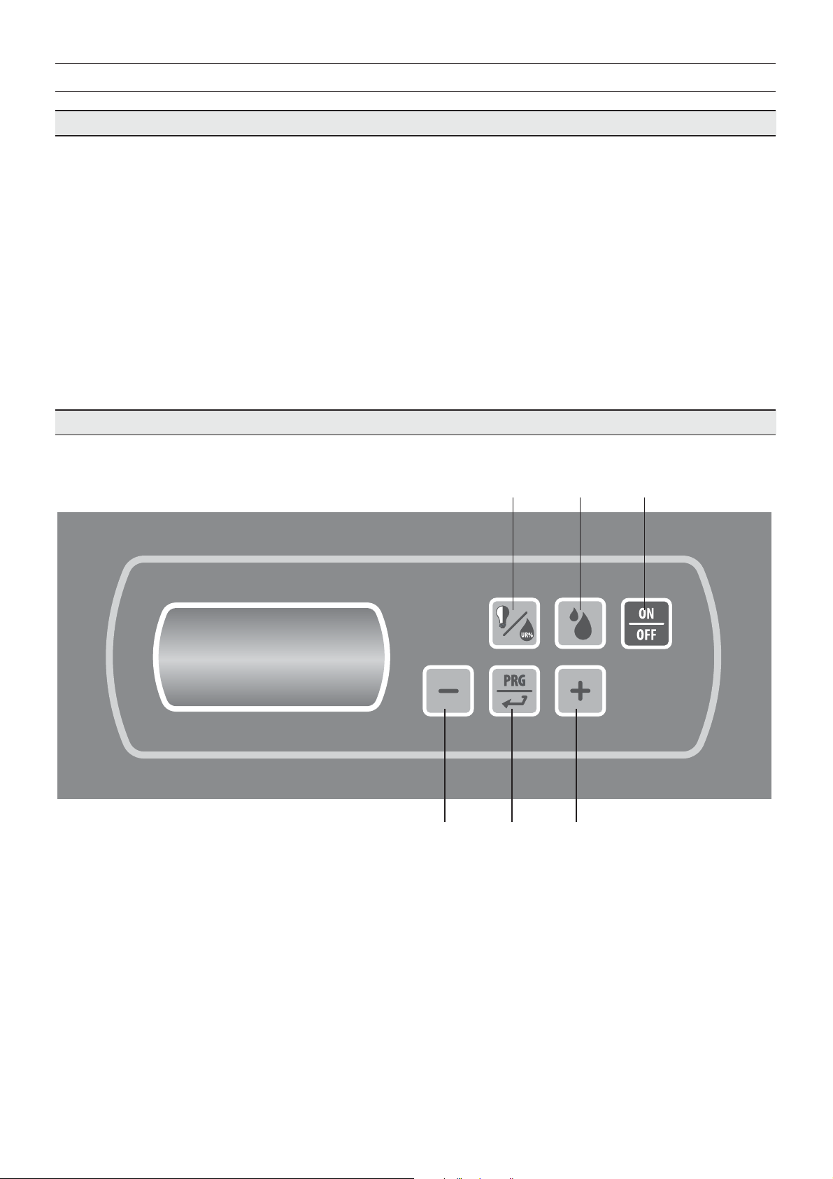
3.2. CONTROL PANEL
P1 P2 P3
Fig. 20
P4 P5 P6
P1: Light/humidity key
P2: Manual defrosting key
P3: ON/Stand By key
P4: Values decrease key
P5: Programming key
P6: Values increase key
15
Page 16
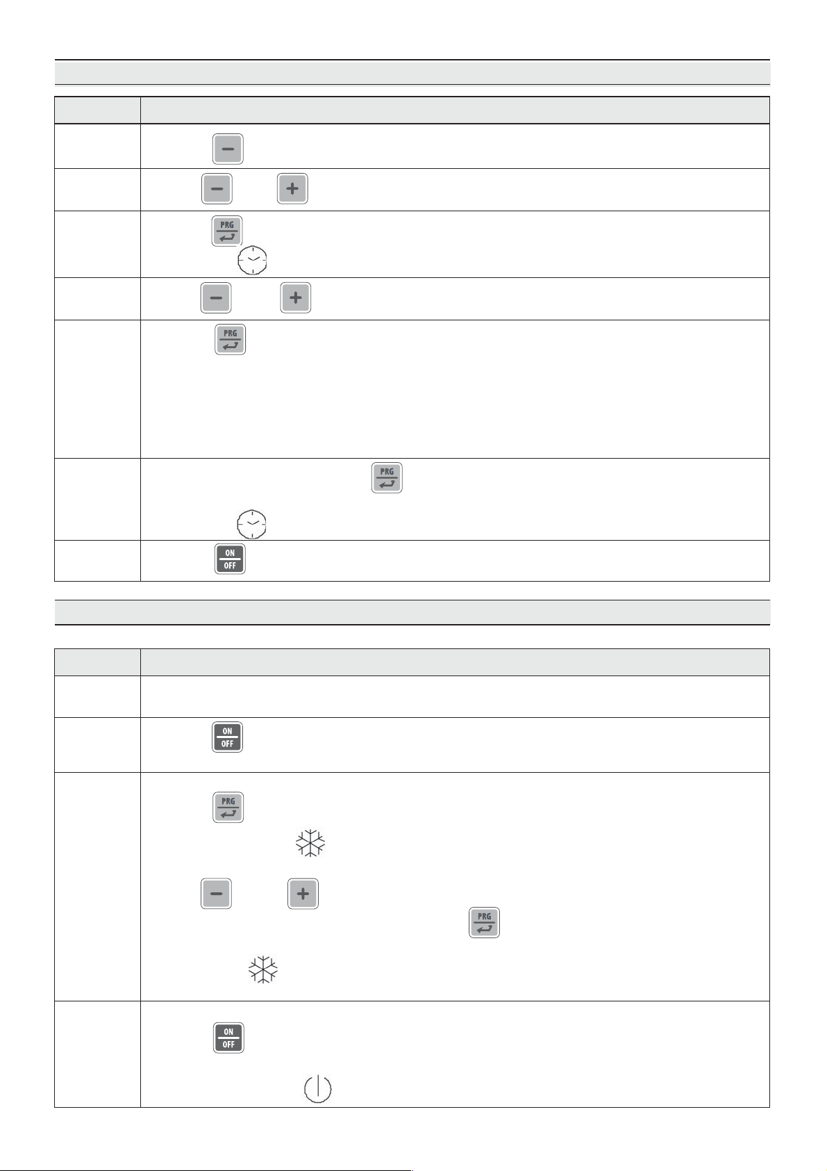
DATE AND TIME ADJUSTMENT
DescriptionPhase
1
2
3
4
5
6
Press P4 for 1 second
Use P4 or P6 to select “rtc” on the display
Press P5 to confirm and access the clock setting menu.
The indicator flashes
Use P4 or P6 to select the current year (last 2 digits e.g. 2011 = 11)
Press P5 to confirm and move on to the following setting.
In sequence:
- YEAR (display: “YY 01”)
- MONTH (display: “nn 01”)
- DAY (display: “dd 01”)
- HOUR (display: “hh 01”) in 24 hour format
- MINUTES (display: “nn 01”)
After setting the minutes, press P5 to confirm and save
the clock setting. "rtc" appears on the display.
The indicator goes off.
7
Press P3 to exit the menu.
3.3. DESCRIPTION AND OPERATION
Preservation cycle
1
2
3
With the cabinet holder in Stand-by, select the operating mode.
See paragraph Common functions ☞ Operating mode selection.
Press P3 for 2 seconds to start preserving.
– The display shows the detected cell temperature
Changing set temperature:
Press P5 :
– The indicator flashes
– The display shows the setpoint
Use P4 and P6 to change the setpoint
– Do not press any key for 15 seconds or press P5 to exit
and save the modification.
DescriptionPhase
– The indicator stops flashing
– The display shows the detected cell temperature
4
Finish preserving
Press P3 for 2 seconds
– The display turns off ☞ cabinet holder Stand-by
– The indicator turns on
16
Page 17
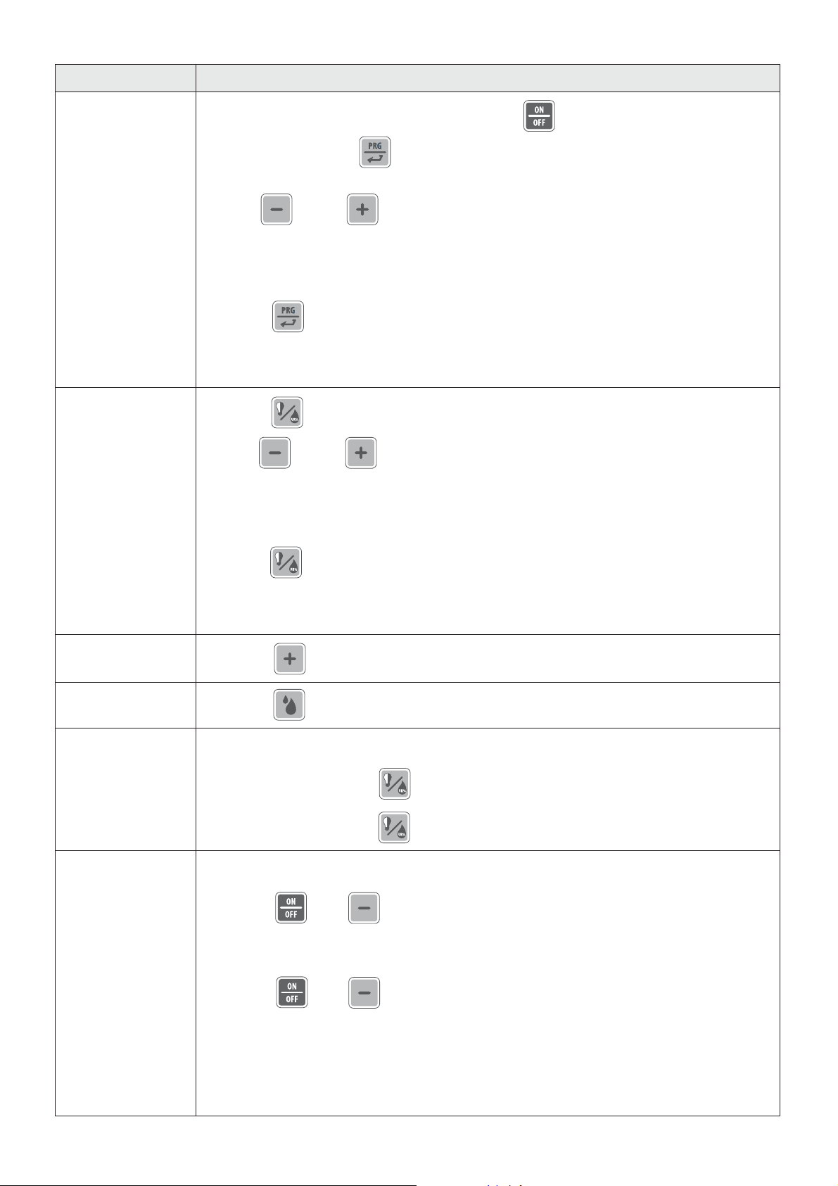
Common functions
DescriptionFunction
Operating mode
selection.
Humidity control
(for POSITIVE
or CHOCOLATE
mode)
Put the cabinet holder in Stand-by by pressing P3 .
Press P5 for 4 seconds .
The display shows the set operating mode.
Use P4 and P6 to set the desired operating mode
where:
POS = POSITIVE mode
NEG = NEGATIVE mode
CIOC = CHOCOLATE mode
Press P5 to confirm the data entered and exit the menu.
If no key is pressed, after a pre-set time
one automatically exits the menu and the entered data is saved.
Press P1 for 4 seconds.
Use P4 and P6 to set the relative humidity level
desired, where:
Ur1= low humidity
Ur2= average humidity
Ur3= high humidity
Overcooling
Manual defrost
Switching on
of cell light
Key locking
Press P1 to confirm the data entered and exit the menu.
If no key is pressed, after a pre-set time
one automatically exits the menu and the entered data is saved.
Press P6 for 4 seconds to start up the Overcooling cycle.
Press P2 for 4 seconds to start up the Manual defrost cycle.
Upon door opening, the light inside the cell is automatically switched on.
With the light off, press P1 to switch the light on inside the cell.
With the light on, press P1 to switch the light off inside the cell.
To lock operation of the keys:
Press P3 + P4 simultaneously for 1 second.
The display shows "Loc" for 1 second.
To unlock operation of the keys:
Press P3 + P4 simultaneously for 1 second.
The display shows "UnL" for 1 second.
17
Page 18
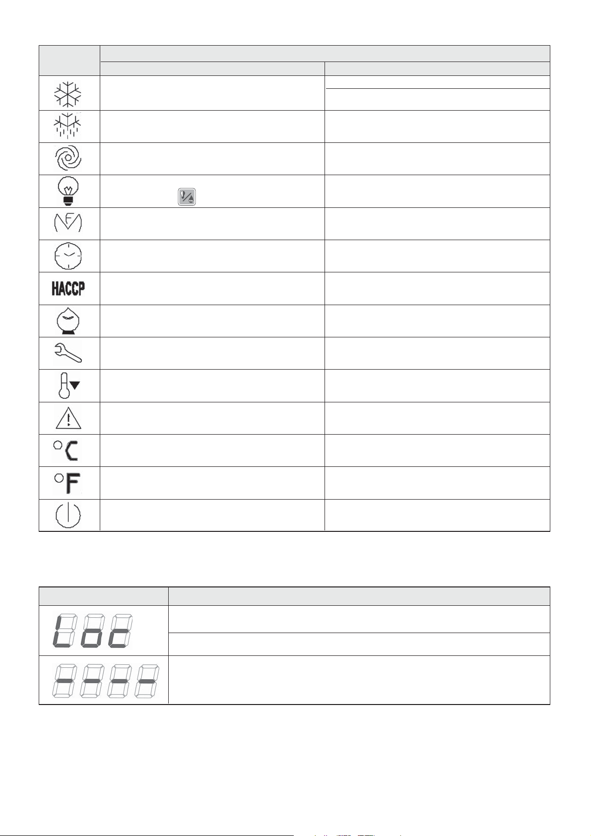
Signals
Indicator
Steady Flashing
Compressor command
Defrosting in progress
Evaporating fan command
Light inside cell manually switched on
by pressing P1
Liquid line solenoid valve command
NOT USED
All information regarding
the HACCP alarms
NOT USED
Meaning
Change temperature set point
Compressor run requested but pending
safety time end
Defrosting in progress but pending
compressor safety time end
During evaporating fan stop time
Internal cell light switched on for door opening
NOT USED
Date and time change in progress
At least one new HACCP alarm
was recorded.
NOT USED
Indications
NOT USED
OverCooling cycle in progress
Alarm or error is in progress
The temperature unit of measurement is °C
The temperature unit of measurement is °F
The instrument is in standby
Display
Key lock activated
NOT USED
NOT USED
NOT USED
NOT USED
NOT USED
NOT USED
Meaning
Running set point locked
Operation required not available
18
Page 19
3.4. STOP MODES
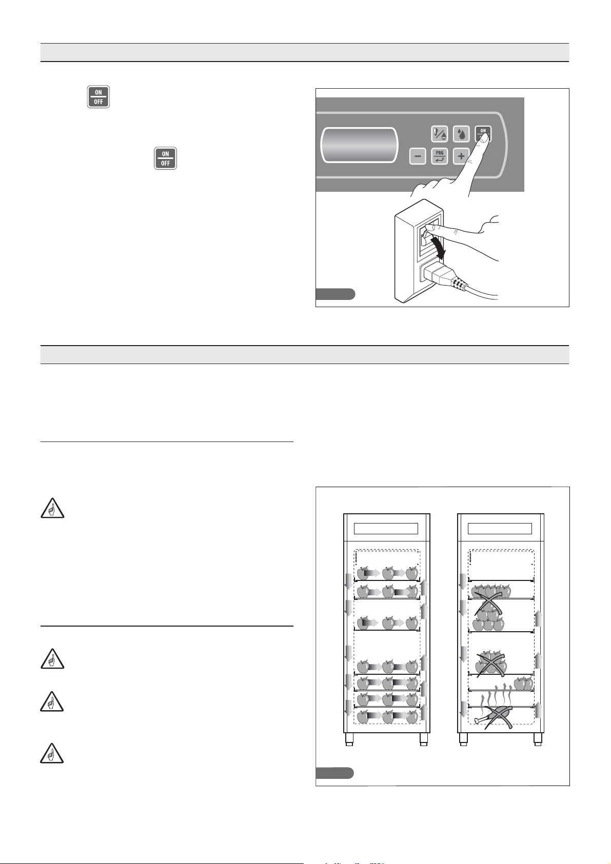
In case of emergency, to switch off the cabinet holder,
press P3 for 2 seconds and disconnect power
supply.
ATTENTION! Press P3 with machine running to
place the cabinet holder in Stand-by: all the commands
are removed from the various components; the cabinet
holder IS NOT DISCONNECTED FROM THE POWER
SUPPLY.
3.5. RECOMMENDATIONS FOR USE
Before starting the machine, clean the inside of the cell
thoroughly ( see par. 4.2).
Fig. 20
Fig. 21
3.5.1. Pre-cooling
Before using the cabinet holder for the first time or after a
period of downtime, pre-cool the cell by running the
machine on empty until the operating temperature is set.
In order to have good machine performance and
not have deterioration of food, we recommend you:
•
do not put hot foods or liquids in containers without
lids into the cell.
•
arrange the products in order to favour cold air circulation throughout the cell.
•
avoid opening the door for a prolonged time and
frequently.
3.5.2. Loading the machine
Maximum load per shelf: 35 kg
Make sure that a sufficient space is left between
the trays for suitable air circulation.
If the machine is not completely loaded, distribute
the trays and the load over the entire useful height
avoiding accumulation.
OK! NO!
When the CP ONE is used in Positive mode
(20÷0°C), run the cabinet holder on empty for at least 4
hours in order to work at the desired relative humidity.
Fig. 22
19
Page 20
4. MAINTENANCE
4.1. ROUTINE MAINTENANCE:
The information and the instructions in this chapter are
intended for all staff operating the machine: the user, the
maintenance technician and the unskilled staff.
Elementary Safety Standards
To carry out routine cleaning and maintenance safely,
follow the safety regulations of (
•
do not touch and operate the machine with humid or
wet hands or feet,
•
do not insert screwdrivers, kitchen tools or any other
object between the protections and moving parts
•
before performing any cleaning or routine maintenance
operation, disconnect the machine from the electrical
power supply by turning the main switch off and removing the plug.
do not pull the power supply cable to disconnect the
•
machine from the power supply mains.
Fig.23) :
It is prohibited to remove the protections and safety
devices in order to perform routine maintenance. The
Manufacturer declines any liability for accidents caused by
failure to comply with the aforementioned obligation.
Before starting the machine, clean the inside of the
cell thoroughly, as indicated in paragraph 4.2.
4.2. CLEANING THE CELL
In order to guarantee hygiene and protection of the quality
of the foodstuffs treated, the internal cleaning of the cell
must be performed frequently, depending on the type of
food preserved.
Weekly cleaning is recommended.
The conformation of the cell and the internal components
can be washed using a cloth or sponge.
Clean using water and non-abrasive neutral detergents.
Rinsing can be done with a cloth or sponge soaked in
water, or with a
moderate jet of water (not exceeding the mains pressure).
Do not scrape the surfaces with sharp or abrasive
bodies.
Fig. 23
Fig. 24
Do not use abrasives or solvents and thinners.
Always wear protective gloves during the
cleaning operations.
Do not use cleaning agents containing acetic acid
and derivatives or ammonia;
Do not use the holding cabinet in direct contact with
products emanating acetic acid and derivatives or
ammonia
20
Page 21
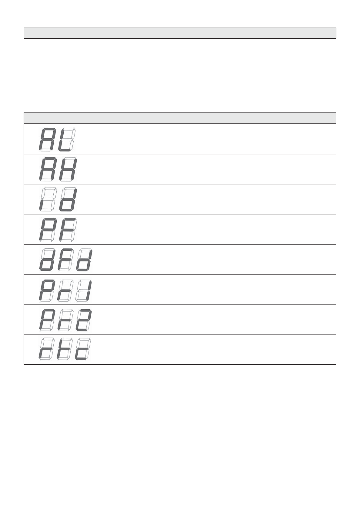
4.3. TROUBLESHOOTING
The machines' electronic control is supplied with a sound
and visual signal system which signals the presence of an
alarm; press a key to silence the sound alarm.
Diagnostics managed by the electronics:
Display
Meaning
Minimum temperature (HACCP alarm)
Maximum temperature (HACCP alarm)
Open door (HACCP alarm)
No voltage (HACCP alarm)
Defrosting ended due to maximum duration
Faulty chamber probe
Faulty evaporator probe
Clock error
21
Page 22
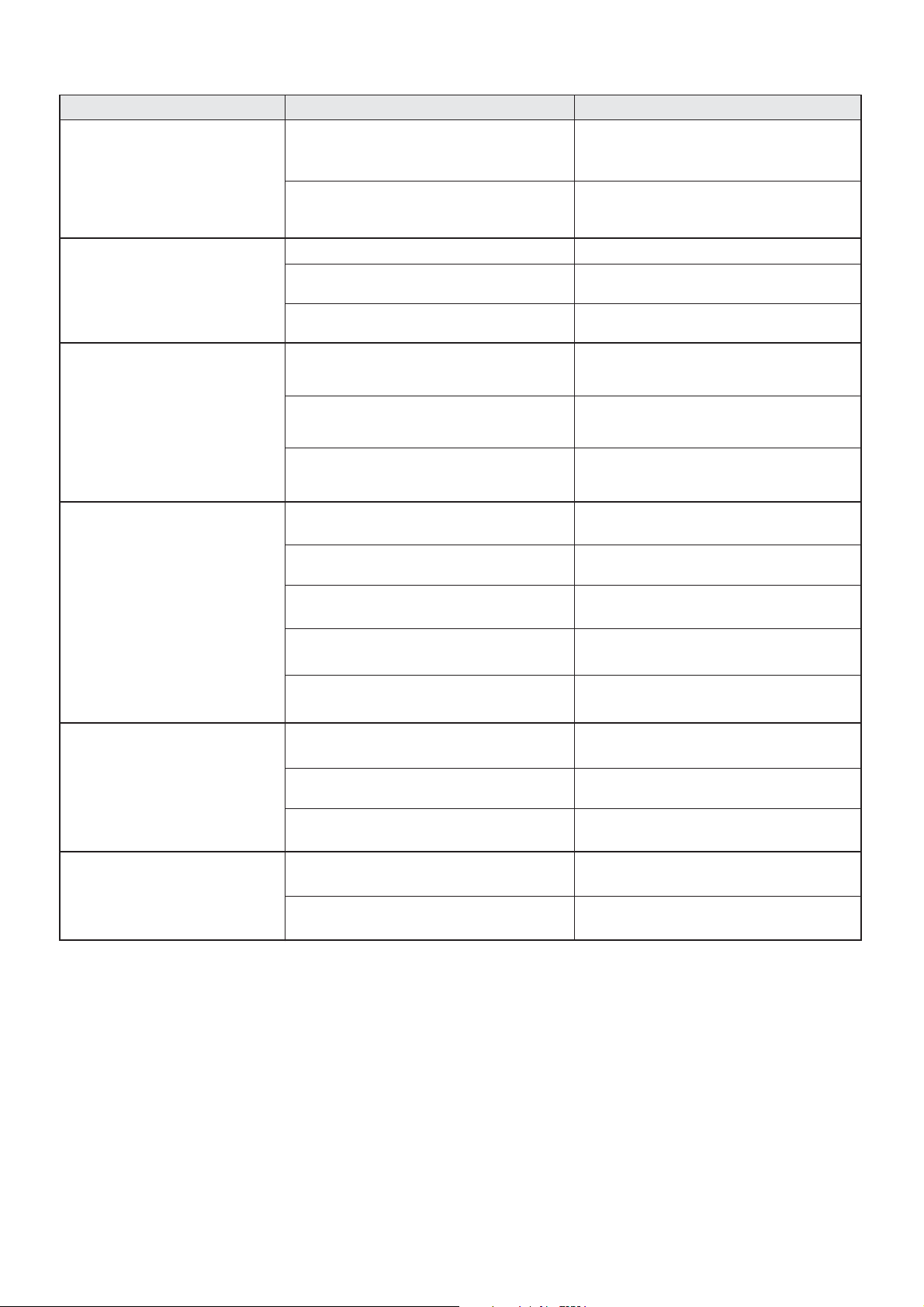
Diagnostics NOT managed by the electronics:
MALFUNCTION POSSIBLE CAUSE POSSIBLE SOLUTION
No power supply Check the connection to the electrical line
The cell front board does
not switch on
Protective fuses triggered Fuse replacement by an authorised
technician
The cell fans do not turn
The compressor does
not function
The compressor functions but
does not cool the cell
No power supply
Faulty fan
Faulty board
No power supply Verificare l'allacciamento alla linea elettrica
Intervention of the internal Klixson
due to overloads
No electronic board consent Check the connection to the electrical line
No coolant gas Technician intervention
Faulty solenoid valve Technician intervention
Dirty condenser Clean condensing battery
Faulty liquid line solenoid valve Intervention of a technician to replace
Faulty defrost line solenoid valve Intervention of a technician to replace
Check the connection to the electrical line
Technician intervention to replace
the board
Technician intervention to replace
the board
Intervento di un tecnico
the solenoid valve or coil
the solenoid valve or coil
The condenser fan does
not function
No evaporator
defrosting
No power supply Check the connection to the electrical line
Faulty fan Intervention of a technician
to replace the fan
No electronic board consent Technician intervention to replace
the electronic board
Defrosting cycle incorrect programming Control defrosting cycles programming
Faulty defrosting line coil or solenoid valve Intervention of a technician to replace
the solenoid valve or coil
22
Page 23
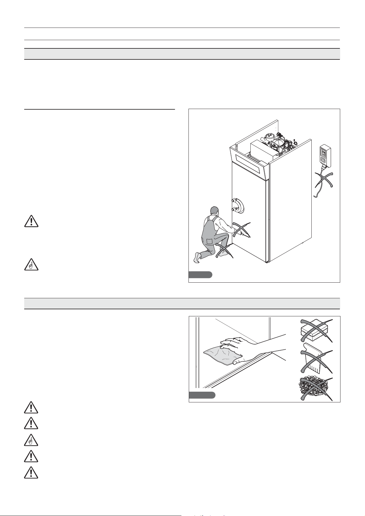
4.4. EXTRAORDINARY MAINTENANCE
The information and instructions in this paragraph are
destined exclusively to the specialised staff authorised
to intervene on the electrical and refrigerator components of the machine.
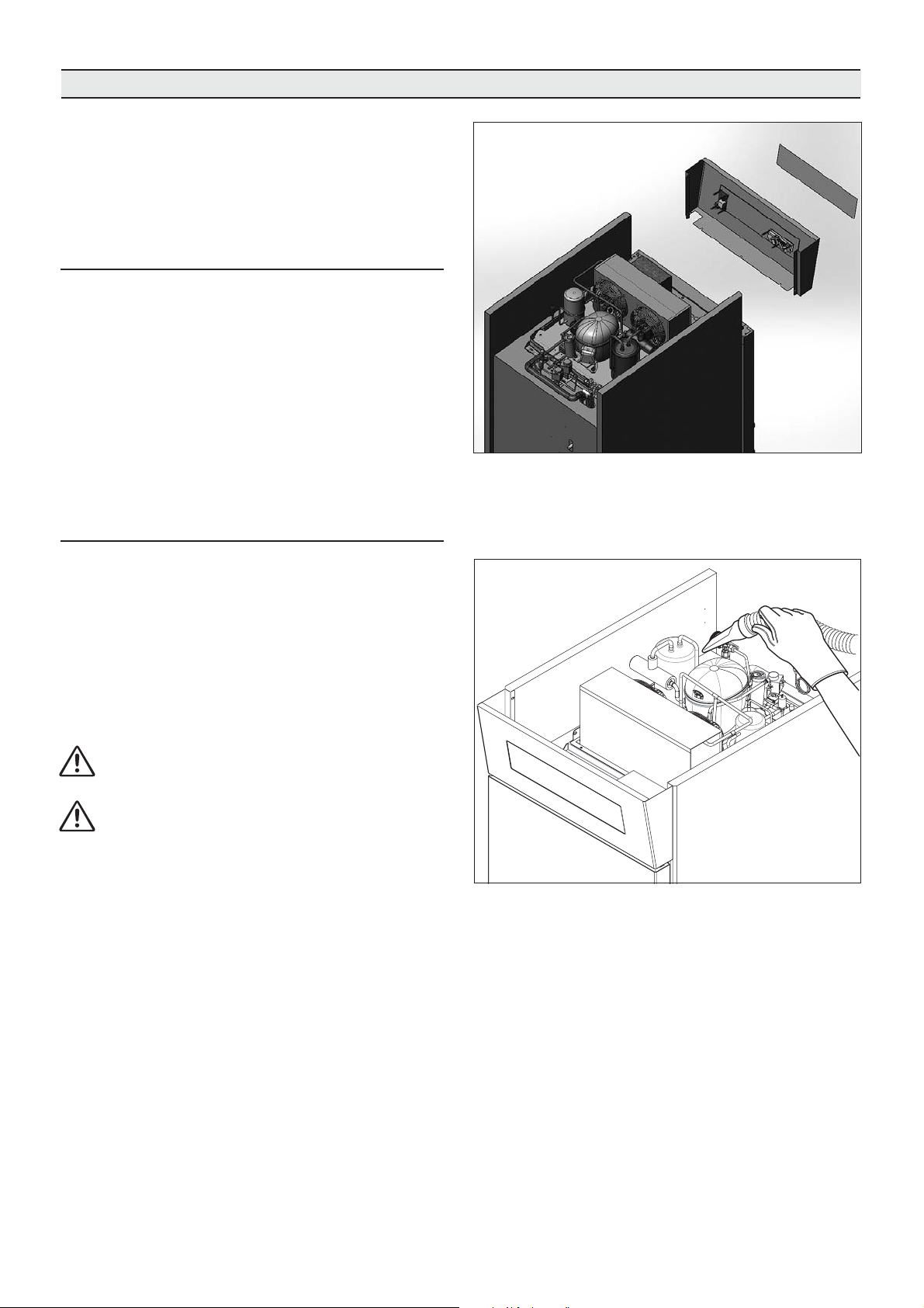
4.4.1. How to access the electronic boards and the
electrical control panels.
The electronic boards and the electrical control panels
are located on the top part of the machine, protected by
a metal sheet. Remove the electrical power supply
before intervening for maintenance. Then remove the
steel cover, unscrewing the locking screws.
At the end of maintenance operations, accurately reassemble the covers and tighten the locking screws.
4.4.2. Cleaning the condenser
For correct and efficient functioning of the cabinet
holder, the air condenser must be kept clean in order to
allow the free circulation of the air. This operation must
be performed every 30 days maximum. It can be carried
Fig. 29
out using non-metal brushes in order to remove all of
the dust and soot from the condenser fins themselves.
The use of a suction device is recommended in order to
prevent the dispersion of the dust removed into the
environment. Whenever there are greasy deposits, use
a brush soaked in alcohol.
Fig. 28
Do not scrape the surfaces with sharp or abrasive
bodies.
During the above-mentioned operations, always
wear protective gloves, glasses and masks for protection
of the respiratory tract.
23
Page 24

IRINOX
headquarter
via Madonna di Loreto, 6/B
31020 Corbanese di Tarzo (TV) - Italy
production site
via Caduti nei lager, 1
Z.I. Prealpi Trevigiane, loc. Scomigo
31015 Conegliano (TV) - Italy
P. +39 0438 2020
F. +39 0438 2023
irinox@irinox.com
www.irinoxprofessional.com
- Printed in Italy
Cod. 4430141 - n. rev. 01 - 09/2017
 Loading...