

Page 1

O P E R A T I O N A N D
S E R V I C E M A N U A L
N°REV REVISION DESCRIPTION DATE REV. REVISER
01
UPDATE COVER
27/08/2015
NC
Page 2

Dear customer,
We wish to thank you for the trust you have shown us by choosing an IRINOX conservation unit, and we ask you to
carefully read the manual which will provide you with all the necessary information to immediately start optimal
conservation of your products.
We do in any case suggest that you study this manual so as to take advantage of all the potential and benefits that
your IRINOX conservation unit has to offer.
Proper operation of the machine also depends on its proper use.
Keep this manual near your conservation unit, so that it can easily be consulted by you and your operators.
Enjoy working with IRINOX!
Register online with Club Irinox : www.irinox.com
The graphic representation of the commands in this manual makes it easier to understand the operations to be performed, so that you can immediately start satisfactorily using your IRINOX conservation unit.
Legend of symbols
suggestions and details for proper use of the conservation unit
instructions for your safety
Additional information in this manual
Guarantee and service information
Validity of guarantee: for single parts, 12 months from invoice date, as shown in the current price lists.
Contacts:
Customer service: +39.0438.5844
Assistance for use +39.0438.5844
Technical service - spare parts +39.0438.2020
Fax +39.0438.2023
E-mail irinox@irinox.com
Web site www.irinox.com
For any request concerning your conservation unit, always specify:
• The model
• The serial number
which are shown on the label on the machine.
Page 3

CONTENTS
1. GENERAL DOCUMENTATION 4
1.2 INTRODUCTION 4
1.3 TRANSPORT AND HANDLING 4
1.4 UNPACKING AND DISPOSAL OF PACKAGING 5
1.5 BASIC SAFETY INSTRUCTIONS 5
2. INSTALLATION 6
2.1 PLATE DATA 6
2.2 POSITIONING 6
2.3 DIMENSIONAL DATA 7
2.4 AMBIENT TEMPERATURE AND AIR CIRCULATION 9
2.5 COOLING POWERS 9
2.6 ELECTRICAL CONNECTION 9
2.7 REFRIGERATION CONNECTION 11
2.8 CONDENSATION DISCHARGE CONNECTION 13
2.9 CONNECTION OF WATER COOLED UNITS 13
2.10 NOTES FOR INSTALLER 14
2.11 SAFETY AND CONTROL SYSTEMS 14
2.12 R404a GAS SAFETY INFORMATION 15
2.13 DISPOSAL OF MACHINE 15
1.1 GENERAL WARNINGS 4
3. OPERATION 16
3.1 USE 16
3.2 CONTROL PANEL 16
3.3 DESCRIPTION AND OPERATION 16
3.4 SHUTDOWN MODES 16
3.5 SUGGESTIONS FOR USE 19
3.6 PROGRAMMING OF PARAMETERS 20
4. MAINTENANCE / SERVICE 22
4.1 ROUTINE MAINTENANCE 22
4.2 CELL CLEANING 22
4.3 CONDENSER CLEANING 23
4.4 TROUBLESHOOTING 23
4.5 SPECIAL MAINTENANCE 26
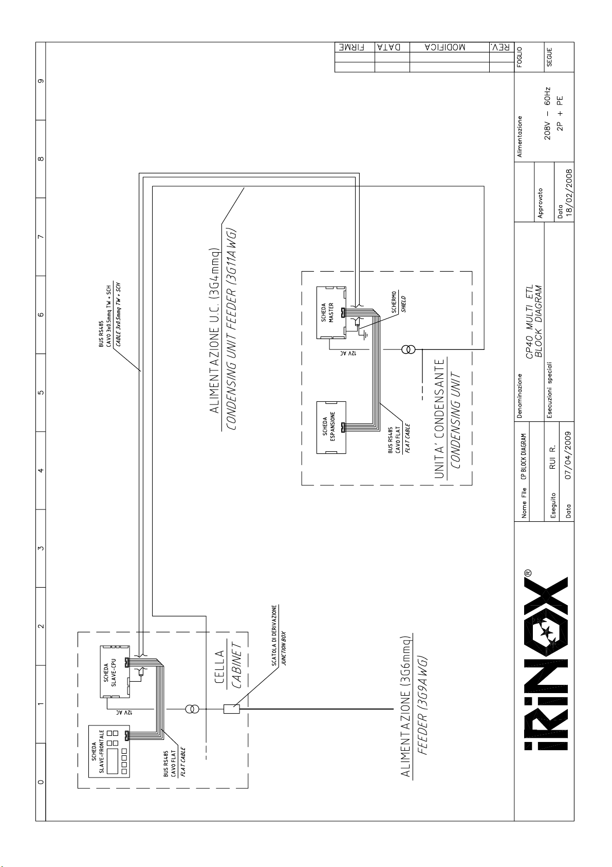
5. BLOCK DIAGRAM 27
3
Page 4

1. GENERAL DOCUMENTATION
1.1. GENERAL WARNINGS
•
This manual is an integral part of the product. It
provides all information required for correct installation, proper use and maintenance of the machine.
•
The user must read this manual and refer to it as
needed. It must be kept in a place that that all authorized workers (installer, user, maintenance technician).
•
The conservation unit is intended for professional
use. Therefore, it is to be used only by skilled personnel.
The conservation unit is intended only for its
•
designed use, i.e. the conservation of foodstuffs.
1.2 INTRODUCTION
Installation must be performed authorized and specialized personnel, respecting the instructions in this manual.
Should the machine be supplied with a remote condenser
unit, it is the responsibility of the installer to check all
•
This does not include products that require constant
monitoring and recording of the temperature, such as:
- heat-sensitive chemical products
- medicines
•
- blood products
The manufacturer shall not be held liable for any damage
arising from incorrect and unreasonable use, such as:
- improper use by untrained personnel.
- modifications or works which are not specific to the
model.
- use of spare parts which are not original or not
specific to the model.
- failure to comply with even a part of the instructions
in this manual.
connections and to issue a declaration that the installation was duly performed and is in accordance with the
aforementioned directive.
1.3 TRANSPORT AND HANDLING
•
Loading and unloading of the machine on the means of
transport can be performed using a forklift or pallet truck
with forks that are more than half as long as the cabinet.
The hoisting apparatus must be suitably chosen on the
basis of the size and mass of the packaged machine as
indicated on the package label (
see Table 1).
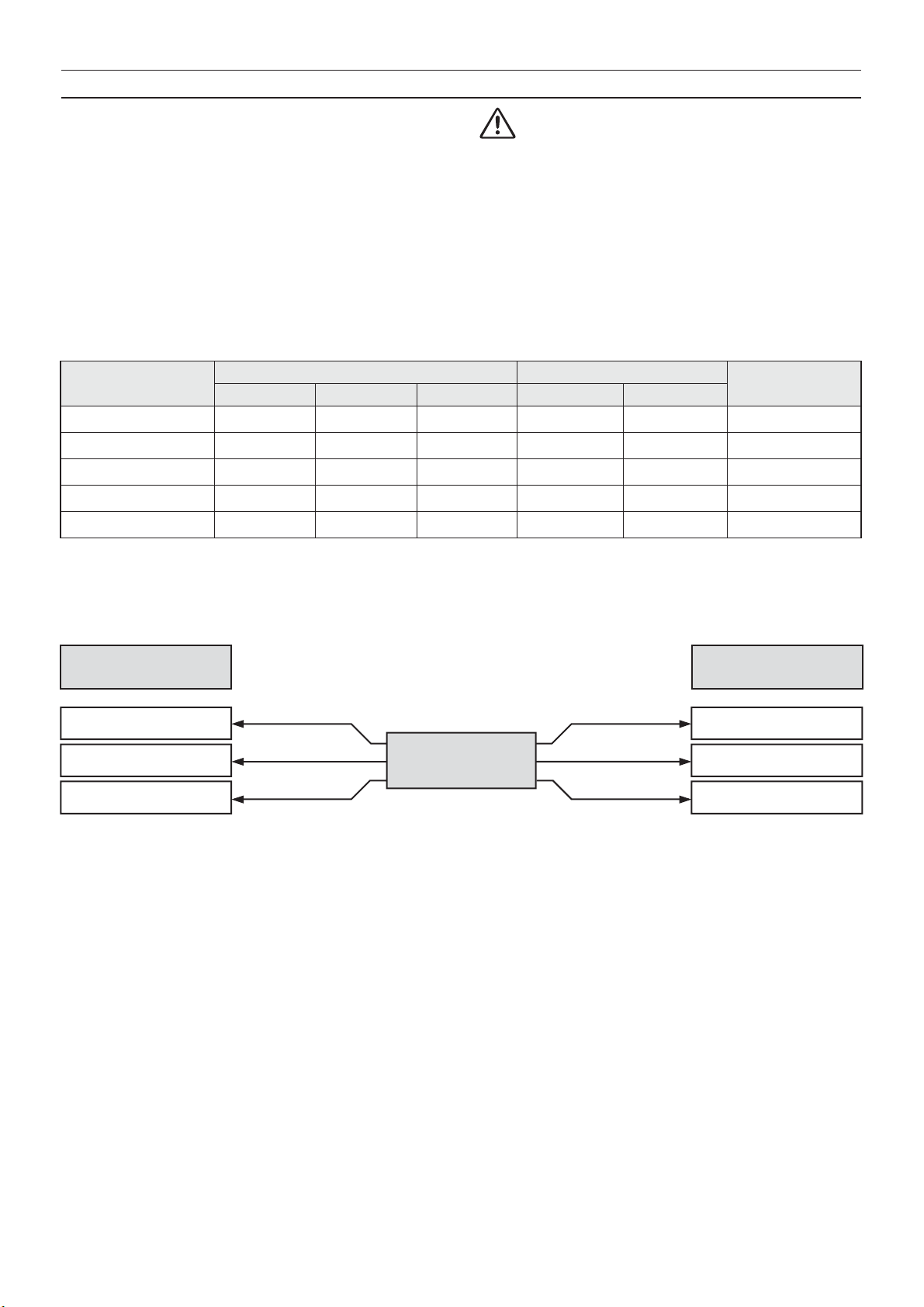
Table 1
NET
WEIGHT
oz
Model of conservation units
CP40 + U.C.
BUILT IN
CP40
Model of condensing units
C504
* Streamlined condensing unit. NOTE: Cell with glass doors +20kg
10406-10864*
8466
1905-2399* 36.2 29.5 34.6 21.2 2751-3245* 36.2 29.5 34.6 21.2 2751-3245* 37.8 27.6 33.9 21.2 3245-3739*
CARDBOARD PACKAGING CAGE PACKAGING CRATE PACKAGING
L H D cu ft oz L H D cu ft oz L H D cu ft oz
39.4
102.4
51.2
123.6
11640-12099*
39.4
98.4
51.2
123.6
9700-90.6-36.2-39.4-121.8-11817-92.5-61.0-41.3-137.7-14462
•
All necessary precautions must be followed when
handling the chiller to prevent damage to it and the
instructions on the package must be respected.
4
Page 5

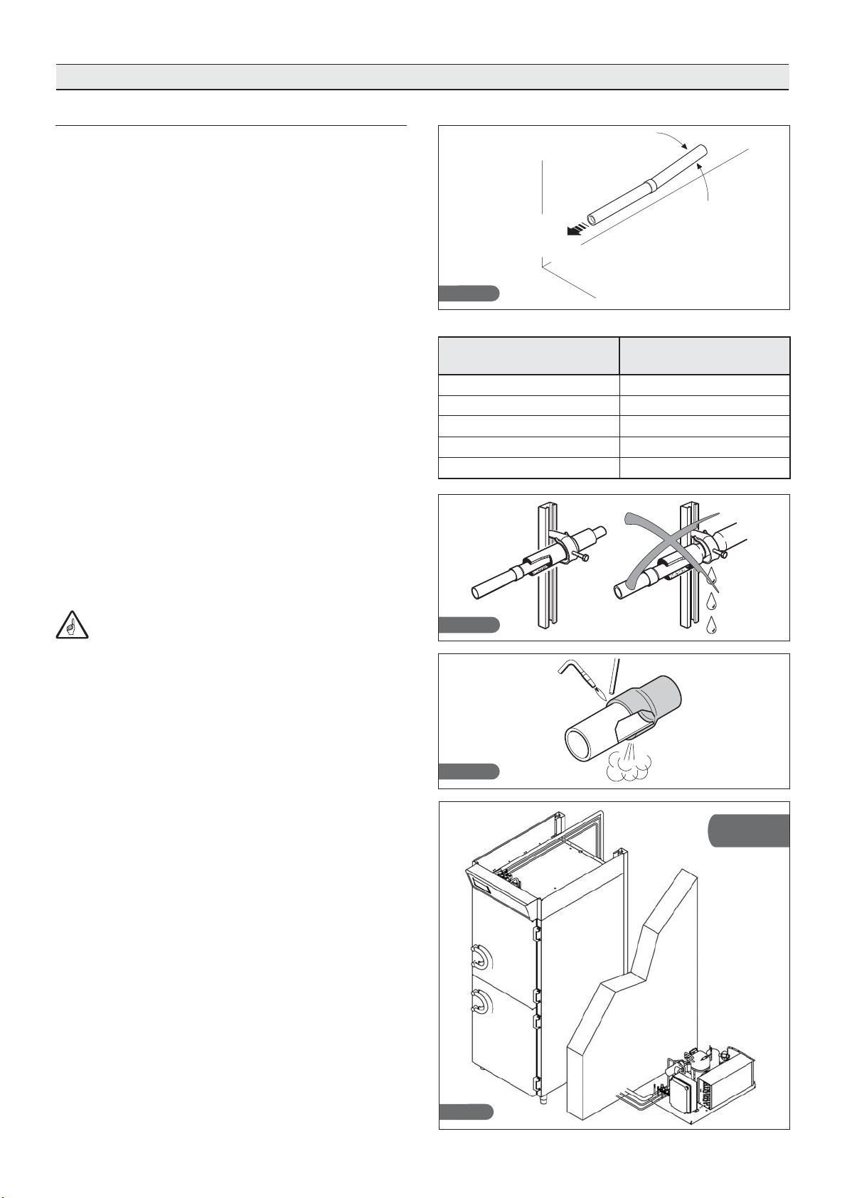
1.4. UNPACKING
•
Remove the cardboard or wooden packaging or box
from the wooden base on which the machine is
standing,
lift the machine using suitable equipment (forklift),
remove the wooden base and stand the machine in
the chosen place (
•
Check the condition of the conservation unit after
having removed the packaging.
•
Remove the protective PVC film from all sides (fig. 1).
•
Use protective gloves to handle the packing
and the wooden base.
•
N.B.: all the various parts of the packaging must be
disposed of according to the rules of the various
Countries in which the chiller will be used. In any case,
none of the packaging must be left in the environment.
see par. 2.2).
1.5. BASIC SAFETY INSTRUCTIONS
If the instructions in this manual are not followed, the
user takes upon himself responsibility for any
operations carried out on the machine.
These are the safety rules in general:
•
do not touch the machine with damp hands or feet
do not work on the machine barefoot
•
do not insert screwdrivers, kitchen utensils or other
•
objects between the guards and moving parts
before cleaning or carrying out routine maintenance,
•
disconnect the machine from the mains by turning the
main switch off and removing the plug
do not pull at the cable to unplug the machine.
•
Fig. 1
5
Page 6

2. INSTALLATION
2.1. PLATE DATA
•
Check that the data on the plate and the electric
power supply characteristics correspond (V, kW, Hz,
no. of phases and available power).
•
The plate with the characteristics of the unit is found
on the right side of the conservation unit (fig.2) and
under the control panel.
Preparation of machinery rooms for the condensing
units must comply with fire prevention standards in the
country of installation. Contact the local fire department
for instructions.
Also keep in mind that the intervention of safety
valves or fuse plugs in the refrigerating circuit will result
in the immediate discharge in the environment of all the
coolant used. Please arrange for suitable disposal
methods and emergency measures as shown in the
coolant technical data sheet ( see par. 2.12).
Mod.
y/n
V
A
Compressor HERMETIC
Refrigerant R404 Charge
Design pressure (Low)
Design pressure (High)
Class Volume
Rated Load
IP
PED Code
Fig. 2
31010
CORBANESE (TV)
ITALY
Ph Hz
Kw
KPa
KPa
Model
Serial number
mm/yy/progres.
Frequency
Power
Phase
Volt
Power input
Climatic classes:
T class tropical (ambient temperature between 64,4°F
•
and 109,4°F) in accordance with standard CEI EN
60335-1
•
5 (temperature 104°F, relative humidity 40%) in
accordance with standard UNI EN ISO 23953-2
2.2. POSITIONING
•
The machine must be installed and tested by fully
respecting the accident-prevention standards, traditional precautions and the laws in force.
•
The installer must check for any fire-prevention rules
(consult the local fire department for instructions).
Place the machine in its location.
•
Permanently level the appliance by means of the
•
adjustable feet. Use special hoisting apparatus for
the heaviest machines (fig. 3).
If the cells are not levelled, their proper functioning and
•
the drainage of condensation may be jeopardized.
Fig. 3
Avoid (Fig.4):
•
Places exposed to direct sunlight
•
Closed locations that are hot and have poor air circulation ( see table 2).
Avoid installing the machine near any source of heat.
•
Fig. 4
6
Page 7

2.3. DIMENSIONAL DATA
200 [7.9inc]
Standard built-in unit
900 [35.5inc]
120 [4.7inc]
650 [25.6inc]850 [33.5inc]
2560 [100.8inc]
2360 [93.1inc]
920 [36.2inc]
1245 [49inc]
2140 [84.4inc]
120 [4.8inc]90 [3.6inc]
COMBINATION OF CONDENSING UNITS
MODEL CP
U.C. MODEL
CP40 C504
2360 [93.0inc]
2220 [87.5inc]
60 [2.4inc]
140 [5.5inc]
900 [35.5inc]
Max door opening 130°
780 [30.8inc]
900 [35.5inc]
690 [27.0inc]
60 [2.4inc]
560 [22.0inc]
1"
CP40
430 [16.8inc]
250 [9.8inc]
2000 [78.7inc]
Hot gas line
Liquid line
Suction line
7
Page 8

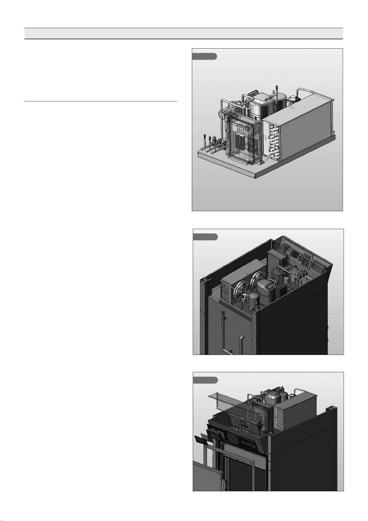
2.3. DIMENSIONAL DATA
Condensing unit C504
Air cooling
Air/city water cooled
Cooled with well
water or city water
Streamline option
Dimensions of remote condensing unit.
MODD.
DIM.
L
P
H
oz
C504
MODD.
STREAMLINED
AIR/WATER
WATER
AIR
33”
22”
17”
1905
33.5”
22.5”
19.0”
2398
8
Page 9

2.4. AMBIENT TEMPERATURE AND AIR CIRCULATION
For air cooled refrigeration units, the air temperature in
the place of operation must not exceed 107,6°C.
Declared performance cannot be guaranteed if this
temperature is exceeded.
The remote condensation units must be installed in
special rooms or outdoors, protected against direct
sunlight. If circumstances make it necessary, the installer
must decide whether to provide a covering or shelter.
Sufficient air circulation must however be ensured.
For greater details see table 2.
2.5. COOLING POWERS
Table 4
MODEL
C504 2748
Declared values at T.evap=-14°F and T.cond.=104°F. Superheating in
accordance with EN12900.
Cooling yield [W]
1807
Condensation power [W]
Table 2
MINIMUM AIR CIRCULATION FOR CONDENSING UNITS
MODEL yd/h AIR
C504 1439
Table 3
MAXIMUM WATER CONSUMPTION FOR AIR COOLED CONDENSING UNITS
MODEL
C504 140
Values referred to the declared condensation power at 14/104°F in
accordance with EN12900.
Well water [gal/h] City water [gal/h]
42,3
2.6. ELECTRICAL CONNECTION
Up the line from each unit (cell and condensing unit) it
is obligatory to install an automatic circuit breaker in
compliance with the laws in force in the Country of
installation.
The power supply is to be carried to the electrical
panel of each single unit, as per the data in Table 5.
•
The electrical power cables must be properly sized
for the units installed;
•
The electrical cables must be placed and fastened in
the cable passage, and laid suitably for the place of
installation;
•
Each wire must be inserted to the corresponding
terminal.
•
The earth wire must be correctly connected to an
efficient earthing system.
Fig. 6
Fig. 7
9
Page 10
BUS cable for communication between condensing unit and cells
Twisted and shielded cable 3x0.5mm2 maximum length
100m.
Connect the cable to the terminals of the electronic
cards as shown in the block diagram and in the electrical diagrams. Comply with the codes on the terminal
block. The sequence of connection of the units does
not make any difference. Start with the BUS of the
Master card (condensing unit).
Connect the shield of the BUS cable to earth only in the
electrical panel of the condensing unit.
Table 5
MODEL
Voltage (V)
Cabinet CP40 208 2P + PE 1,2 5,8 3G11AWG
POWER SUPPLY POWER INPUT
Frequency (Hz)
60
The manufacturer declines any responsibility
or guarantee obligations if damage occurs to the
unit, persons or things due to installation that is
incorrect and/or does not respect the laws in force.
Poles Power (kW) Current (A)
CABLE SECTION
C504A 208
C504M 208 2P + PE 1,2 6,0 3G11AWG
C504W 208 2P + PE 1,1 5,4 3G11AWG
C504S.S. 208 2P + PE 1,2 6,0 3G11AWG
NOTE: cable sized for a length of 25m with industrial voltage drop ∆V% ≤ 1%
A: Air - M: Mixed Air/Water- W: Well water - S.S.: Super Silenced
60 2P + PE 1,2 5,7 3G11AWG
60
60
60
"Unit communication BUS cable"
CELL ELECTRONIC
CARD
GND
B
CABLE 3x0.5 mm
TWISTED
2
CONDENSING UNIT
ELECTRONIC CARD
GND
B
SHIELDED
A
A
ATTENTION! The shield must be connected to earth only in the condensing unit.
If several cells are to be connected with the bus, the shield of the incoming cable must be spliced with the shield of
the outgoing cable. In the cell where the bus ends, the shield must be isolated.
10
Page 11
2.7. REFRIGERATION CONNECTION
2.7.1. Installation at same level
General criteria that must be met for the installation of
remote units:
1)
Slope of pipes (Fig.8)
2)
Tightening of brackets on insulated pipes.
For the quantity of brackets to apply on the refrigeration connecting lines of the remote unit
3)
Hermetic welding (Fig.10).
4)
Creation of vacuum (0.03mBar) in the connection
pipes (delivery and suction). Unless otherwise specified, the condensing unit is charged with freon.
5)
Check vacuum seal of pipes.
6)
Opening of cut-off bibcocks on condensing unit.
7)
Check for leaks.
see table 6.
COMPRESSOR
Fig. 8
Table 6
DISTANCE
Cell -> Remote group
5,5 yd 2
11 yd 3
16,4 yd 5
22 yd 7
27 yd 8
2%
NUMBER OF
BRACKETS
8)
Check of exact gas charge via the liquid flow indicator
located on the condensing unit.
Checking the condensation water circulation and
9)
pressure (system with water condensation).
The criteria listed above are sufficient for installation at the same level (Fig.11)
Fig.9
Fig.10
Installation
at same level
11
Fig.11
Page 12

2.7.2. Installation at different levels
If the remote group is installed higher than the unit (fig.
13), it is necessary to fit a siphon at the beginning of each
departure or upward section (a), at intervals of 2 yd of
difference in level along the return pipe, and at every
arrival (b).
If the remote unit is installed lower than the unit, siphons
are not necessary (fig. 12).
Installation at
dierent levels
Fig.12 Fig. 13
2.7.3. Refrigeration connection of remote groups
Diameters for appliance feed pipes are sized in accordance with the installation distance up to a maximum of
27 yd (
see table 7).
For greater distances please consult the manufacturer.
Table 7
Condensing
unit model
C504 CP40
(1): for unit with remote condenser
Model
of
matched
cell
Delivery
line
0,39“ 0,47“ 0,39“ - -
Suction
line
Hot gas
line
Ø mm
2.7.4 Calibration of pressure switches R404a
For calibration of pressure switches R404a see table 8
Table 8
Model
Low
pressure
(L.P.)
AIR COOLING WATER COOLING
High
pressure
(H.P.)
Fan
start-up
Safety
valve
Low
pressure
(L.P.)
The insulation of suction and hot gas pipelines
must be carried out using good quality insulators of the
closed-cell type having a minimum thickness of 19 mm.
Condenser
inlet line
Condenser
output line
0,74“
Note: all units without a unit of measure are expressed
in (relative pressure).
High
pressure
(H.P.)
Safety
valve
PSI - PSIPSI PSI PSIPSI
C504 0 0min min 363400 247 428 413
PSI -
12
Page 13

2.8. CONDENSATION DISCHARGE CONNECTION
For all models, it is necessary to provide a discharge
pipe for the condensation and wash water, with a
minimum diameter of 1", “Geberit" type or similar.
If there is no connection to a drain, install the container
provided for collection of condensation water.
Fasten the support/guide on the bottom of the unit with
the four M6 screws provided.
Fasten the extension pipe to the rear discharge pipe of
the unit (Fig.15).
Insert the container in the support/guide (fig.16).
Ma ke s ur e th at t he e xt en s i o n p i p e i s t i l t e d
towards the container, to prevent water from stagnating
inside of it.
Fig.14
For the position
see par. 2.3.
2.9. CONNECTION OF WATER COOLED UNITS
Fig. 15
Fig. 16
•
When testing (mains water), make sure the machine
is at a standstill, that the water supply is ready and
that water is not coming out of the condenser drain
pipe; in this case, adjust the pressure valve until
water coming out is completely stopped (Fig. 17).
•
We suggest you install a gate valve and a viewable
filter on the water delivery pipeline. The condenser
water delivery and discharge pipes are indicated by
special nameplates. Both fittings are threaded 3/4”F.
•
See Table 3 for maximum water consumption
CHARACTERISTICS OF THE LINE FOR
Maximum inlet pressure of water
Minimum inlet pressure of water
Maximum inlet water temperature to
ensure normal operation of the unit
WATER COOLED UNIT
232 PSI
7,25 PSI
77°F (well water)
104°F (city water)
Fig. 17
13
Page 14

2.10. NOTES FOR THE INSTALLER
Checking for correct installation and testing:
•
Check for possible gas leaks on welded parts or
joints made during installation.
•
Check for proper insulation of pipes connecting the
chiller with the remote condensing unit.
•
Check electrical connection.
•
Check power inputs.
•
Check the standard pressures.
•
Check water connection with the pressure valve
adjustment during operation as well as proper water
condensation circulation.
•
Run at least one complete conservation cycle (reach
the set temperature), and a manual defrost cycle.
Instruct the customer on the exact utilisation
of the chiller with specific reference to the use and
requirements of that specific customer.
Installation and commissioning must be
carried out by authorized personnel.
2.11. SAFETY AND CONTROL SYSTEMS
•
Door microswitch (A): blocks operation of the fans in
the cell when the door is opened
•
Protection fuses (B): protect the circuits against short
circuits and overloads.
•
Fuse holders (C): contain the fuses and allow
opening and disconnection of circuits.
•
Circuit breaker (D): protects the circuits against short
circuits and overloads.
•
Electronic cards (E): based on acquired parameters,
they control the various devices of the machine that
are connected to them.
•
Control of temperature in cell and end of defrosting
(F): managed by the electronic card via probe
PT1000.
•
Safety pressure switch (G): trips in the event of
excessive pressure in the refrigerant circuit.
•
Safety valve (H): trips in the event of excessive pressure in the refrigerant circuit due to failure of the
safety pressure switch.
Fig.A Fig.B Fig.C Fig.D
Fig.E
Fig.HFig.GFig.F
14
Fig. 19
Page 15

2.12. R404A GAS SAFETY INFORMATION
• Identification of hazards
Exposure for long periods by inhalation can cause
anaesthetic effects. Very high levels of exposure may
cause anomalies in heartbeat and cause sudden death.
If the product is nebulized or sprayed it can cause cold
burns to the eyes and skin. It is dangerous for the
ozone layer.
• First aid measures
Inhalation
Move the injured person away from the source of exposure to a warm place where he can rest. If necessary,
administer oxygen. Practice artificial respiration if the
person has stopped, or seems about to stop, breathing.
In the event of cardiac arrest perform CPR. Call for
medical assistance immediately.
Contact with the skin
Thaw the parts concerned using water.
Remove contaminated clothes.
Attention: in the event of cold burns, clothes can
adhere to the skin. In case of contact with the skin,
wash immediately and thoroughly with warm water. If
symptoms occur (irritation or blisters) ask for medical
assistance.
Contact with the eyes
Wash immediately with an eye-wash or clean water,
keeping the eyelids apart for at least 10 minutes. Ask
for medical advice.
Ingestion
Do not induce vomiting.
If the injured person is conscious, make him rinse his
mouth out and drink 200-300 ml of water.
Request medical assistance immediately.
Further medical care
Treatment for symptoms and support therapy where
indicated. Do not administer adrenalin or similar
substances after exposure because of the risk of
cardiac arrhythmia with the possibility of cardiac arrest.
• Fire-prevention measures
Non-flammable.
Thermal decomposition causes the emission of very
toxic and corrosive vapours (hydrogen chloride, hydrogen fluoride). In the event of fire, use breathing apparatus and suitable protective clothes.
Fire extinguishers
Use extinguishers suitable for the type of fire.
• Toxicological information
Inhalation
High concentrations in the atmosphere can cause an
anaesthetic effect and possible unconsciousness. Very
high levels of exposure may cause anomalies in heartbeat and cause sudden death.
Even higher concentrations can cause suffocation
to reduced oxygen content in the air.
due
Contact with the skin
If the product is nebulized or sprayed it can cause cold
burns to the eyes and skin. It does not seem to be
dangerous if absorbed by the skin. Repeated and
prolonged contact can cause loss of natural skin oils
with consequent drying, chapping and dermatitis.
• Ecological information
It breaks down quite quickly in the lower atmosphere
(troposphere). The products or decomposition have high
dispersion features and thus have a low concentration.
It does not promote photochemical smog (i.e. it is not
part of the volatile organic compounds -VOC- in compliance with the UNECE agreement).
Its ozone destruction potential (ODP) is 0.055 measured against a standard ODP of 1 for cfc11 (according
to the uNeP definitions).
This substance is regulated by the Protocol of Montreal
(1992 revision).
Product discharges into the atmosphere do not cause
long-term water contamination.
• Disposal suggestions
The best solution is to collect and recycle the product. If
this is not possible, it must be destroyed in a plant that is
authorised and equipped to absorb and neutralize the
acid gases and other toxic operating by-products.
• Measures to be followed in the event of accidental
dispersion
Make sure that the person eliminating the dispersion is
suitably protected (using special apparatus to protect
the respiratory tract) while cleaning up spills.
If it is safe enough to do so, isolate the source of
dispersion. If the dispersion is modest and ventilation is
sufficient, simply let it evaporate.
For dispersion of large quantities:
- ventilate the area;
- contain the spilled material using sand, soil or other
suitable absorbing material;
- prevent it from penetrating into drains, sewers, basements and construction excavations because the
vapours can cause suffocation.
• Handling
Avoid inhalation of high concentrations of vapours.
Concentrations in the atmosphere must be reduced to
a minimum and kept at the lowest reasonably possible
level, below the professional exposure limit.
The vapours are heavier than the air and for this
reason it is possible that high concentrations form near
ground level where ventilation is scarce. In these
cases, ensure adequate ventilation and wear protective
apparatus for the respiratory tract with a reserve supply
of air. Avoid contact with open flames and hot surfaces
because irritating and toxic products of decomposition
may form. Avoid contact of the liquid with eyes/skin.
2.13. DISPOSAL OF THE MACHINE
Demolition and disposal of the machine must be carried
out in accordance with standards currently in effect in the
country of installation, especially concerning the
refrigeration gas and lubrication oil of the compressor.
15
Page 16

3. OPERATION
3.1. USE
The CP series of conservation units are designed for
the conservation of foodstuffs.
All CPs can work from 59 to -22°F.
In particular
•
In positive mode (59 / 23°F), they are suitable for the
conservation of fresh products or, for short periods, of
cooked foods.
3.2. CONTROL PANEL
DL1: Cell light LED
DL: Compressor operation LED
P1: Relative humidity adjustment key
P2: Cell light on/off key
P3: Enhanced cycle key
P4: Key for download of recorded data
P5: Menu key/value up – reset alarm
P6: Menu key/value down
P7: ON/Standby key
P8: Programming/confirmation key
•
In negative mode (32/ -13°F), they are suitable for the
conservation of frozen products, even for long periods of
time.
•
In chocolate mode (59 / 23°F), they are suitable for
the conservation of chocolate-based products (such as
chocolate based candy).
DL 1
P2 P3 P4 P8
Fig. 20
P5 P7
P6P1DL
3.3. DESCRIPTION AND OPERATION
LED description
Off
DL1DLCell internal light off
No compressor running
Conservation cycle
Description Phase
0
1
Machine power up. For the first three seconds,
the display shows the type of machine set.
Press the key P7 and the machine will start,
shown the screen of phase 2.
Press key P7 again and the machine will go
into standby.
On Flashing
Cell internal light on
At least 1 compressor
running
NOT INCLUDED
All compressors stopped
with one compressor in
timer-control phase for
start-up
Front panel screen
CP40N
27.07.2007 10.35
OFF
27.07.2007 10.35
16
Page 17

Description Phase
Front panel screen
2
Start of machine operation
The display shows:
-0,4°F
SET : -20°C
- cell temperature;
- number of door openings
(at 24:00 each day, the count of
openings is reset);
- set temperature;
- time of next automatic
defrost.
3
4
Modify set temperature
Press keys P5 and P6 to modify the
previously set temperature.
If the data is not modified within 3 seconds,
it is automatically memorized.
End of conservation cycle
If you press key P7 , the machine will end
the conservation cycle and enter standby mode.
-0,4°F
No.: 12
No.: 12
SET : - 4°F
: 12.00
No.: 12
No.: 12
: 12.00
-0,4°F
SET : -20°C
No.: 12
No.: 12
: 12.00
OFF
27.07.2007 10.35
17
Page 18
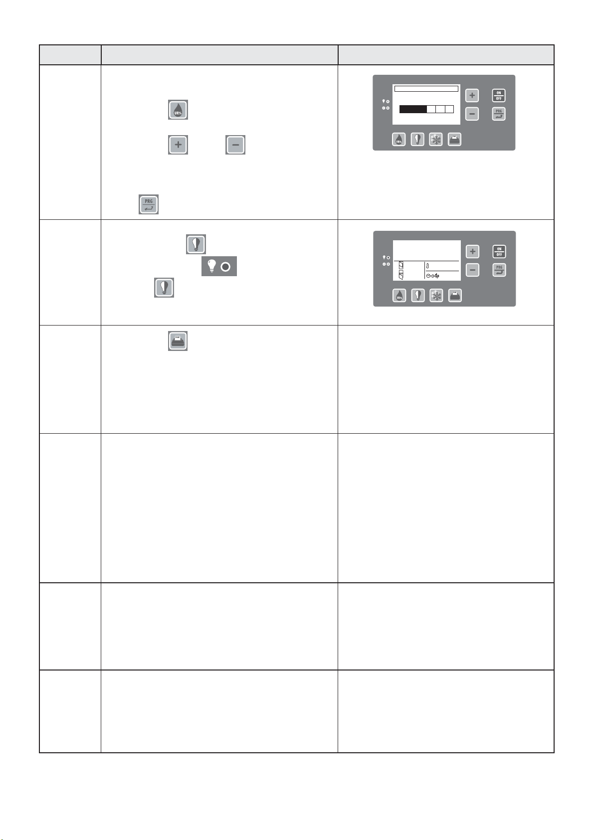
Common functions
Description Function
1
Humidity control (for cells configured as CP
positive, CP positive plus or CP chocolate)
Front panel screen
UR%
-
4
+56
Press key P1 to adjust the percentage of
relative humidity in the cell.
With keys P5 and P6 you can modify
the percentage of humidity displayed, with 6
selectable steps. Confirm the selected steps
by pressing
key P8 or wait 5 seconds without press the keys
2
Turing on the cell light (if present)
Press the key P2 to turn on the light in
the cell and LED DL1 .
-0,4°F
SET : -20°C
No.: 12
No.: 12
: 12.00
Press P2 again and the light goes off.
The light comes on automatically when the
doors are opened.
3
Press key P4 to print the register on a
printer which may be connected to the RS232
serial port. You can download the data onto a
USB key, which is then to be connected to a PC.
Data on temperature, data, and time are downloaded.
The memory holds recordings for 30 days with
measurements made at 15-minute intervals.
4
Selection of operating mode
Each CP can work in 3 different modes,
with default operating sets.
The possible modes are:
• Positive; • Negative; • Ciok (Chocolate)
The operating mode can be varied only when the
machine is in standby.
To access mode selection, follow the instructions in
Par. 3.6 “PARAMETER PROGRAMMING" and
modify parameter 1-8 "Selection of CP model".
The machine is set in the factory with the mode
specified during the order phase.
5
Manual defrosting
Access parameter programming by following the
instructions in Paragraph 3.6 “PARAMETER
PROGRAMMING".
Select manual 4, manual defrosting.
6
Sanification
Access parameter programming following the
instructions in Paragraph 3.6
"PARAMETER PROGRAMMING"
Select "Yes" parameter 1-9 "Sanigen"
18
Page 19

3.4. SHUTDOWN MODES
In case of emergency, to shut down the machine, press
the ON/OFF key and cut off the power supply from the
main panel (Fig.21 ).
3.5. SUGGESTIONS FOR USE
Before putting the machine in operation, it is necessary
to carefully clean the inside of the cell ( see par. 4.2)
OFF
27.07.2007 10.35
Fig. 21
3.5.1. Pre-cooling
Before using the conservation unit for the first time, or
after a long period of disuse, pre-cool the cell by running
the machine empty until the set working temperature is
reached.
To obtain good performance from the machine
without altering foods, we suggest the following:
•
do not place hot foods or liquids in the cell without a
cover.
arrange products so as to favour cold air circulation
•
throughout the cell.
avoid prolonged and frequent door opening.
•
3.5.2. Loading the machine
Take care that there is enough space between pans,
so as to allow sufficient air circulation.
If the machine is not fully loaded, spread the pans
and the load evenly throughout the entire height, avoiding
concentrations.
When using the CP in positive mode (59÷32°F), run
the conservation unit empty for at least four hours so as to
work at the desired relative humidity.
OK! NO!
Fig. 22
19
Page 20

3.6. PARAMETER PROGRAMMING
Access the user parameter programming also with the On card.
Press and hold button P8 until the display shows "user parameters".
Use of keys for navigation in the menus:
- key P8 : confirms the selected value/menu
- key P5 : scrolls the menu up, increases the value of the selected parameter
- key P6 : scrolls the menu down, decreases the value of the selected parameter
Menu/Parameters Diagram:
Menu
Set UP
CP
parameters
Item
1-1
1-2 Summer time
1-3 Language
1-4 Displays
1-5 Contrast
1-6 Print Mod.
1-7 Release software
1-8 Selection of CP model
1-9 Sanigen
2-1 ∆t thaw alarm
2-2
2-3
2-4 Duration of enhanced cycle
2-5 Time of door opening no. 1-2
2-6 Fan speed
2-7
Date / Time
Thaw alarm delay
Display of temp. in defrost
Operating mode of relay of al. RL7
Parameter Value Description
Yes
No
Italian
English
French
German
Spanish
°C / °F
Bar / PSI
Printer
USB key
CP40P
CP40N
CP40CioK
Yes
No
See tab.
"Parameter
Values"
See tab.
"Parameter
Values"
1
2
3
See tab.
"Parameter
Values"
See tab.
"Parameter
Values"
See tab.
"Parameter
Values"
1
2
3
4
sets the time and date of the clock of the machine
adjusts contrast of the display
Portable printer
Download data to PC
shows the versions of software of the
Master, Slave-CPU and Slave-Front cards
Conservation unit positive
Conservation device negative
Conservation device for Chocolate
Enables the Sanificator
Disables the Sanificator
shows the message "defrost" during
defrosting
displays the cell temperature
for the entire time of defrosting, it shows
the temperature measured in the cell prior to
the start of the defrost cycle
allows variation of the speed of the fans
in the cell in manual mode
in case of power outage
only for shutdown alarms
thaw alarm AL06
thaw alarm AL06 - power outage
2-8 Frequency of recordings
See tab.
"Parameter
Values"
20
Page 21

Menu
Defrosting
parameters
Manual
defrosting
Info
Alarms
Recordings
Item
2-9
3-1 Time of 1st defrost
3-2 Time of 2nd defrost
3-3 Time of 3rd defrost
3-4 Time of 4th defrost
3-5 Interval between 2 defrosts
3-6 Temperature at end of defrosting
3-7 Max. defrost time
4 Start the manual defrost cycle
5-1 Cell temperature
5-2 Evaporator temperature
5-3 Ambient temperature
5-4 Low pressure
5-5 High pressure
5-6 Working hours of compressor 1
5-7 Working hours of compressor 2
5-8 Working hours of compressor 3
5-9 Working hours of compressor 4
5-10 Status of the evaporator fan
6
7
Chilling set
Display
Print
Parameter Value Description
See tab.
"Parameter
Values"
See tab.
"Parameter
Values"
See tab.
"Parameter
Values"
See tab.
"Parameter
Values"
See tab.
"Parameter
Values"
See tab.
"Parameter
Values"
See tab.
"Parameter
Values"
See tab.
"Parameter
Values"
Temperature set for chilling during
enhanced cycle
Display the list of alarms
Insert the start and end date of the recordings
to be shown . Choose "Display" and the
recording will appear for the selected interval
Insert the start and end date of the
recordings to be printed. Select "Print" to
print the recordings of the selected interval
Adjustment of parameter values:
Item Name Range
2-1 ∆t thaw alarm 1÷30°C 1°C 50°F 50°F 50°F 50°F
2-2 Thaw alarm delay 1÷30 min. 1 min. 20 min. 20 min. 20 min. 20 min.
2-3 Display of temp. in defrost 1-2-3 1 3 3 3 3
2-4 Duration of enhanced cycle 10 min.÷6 h 10 min. NO NO 2 h 4 h
2-5 Time of door opening no. 1-2 1÷30 min. 1 min. 3 min. 3 min. 3 min. 3 min.
2-6 Fan speed 100÷40% 1% 100 % 100 % 100 % 100%
2-7
Operating mode of relay of al. RL7
2-8 Frequency of recordings 15 min.÷4 h 15 min. 30 min. 30 min. 30 min. 30 min.
2-9 Chilling set 1F04÷1F03 0,1°C NO
3-1 time of 1st defrost
3-2 time of 2nd defrost
3-3 time of 3rd defrost
3-4 time of 4th defrost
3-5 Interval between 2 defrosts 1÷24 h 1 h 12 h 6 h 12 h 6 h
3-6 Temp. at end of defrosting 1÷50°C 1°C 39,2°F 39,2°F 39,2°F 39,2°F
3-7
Max. defrost time 2÷99 min. 1min. 6 min. 6 min. 6 min. 6 min.
CP+ = Conservation unit positive; CP- = Conservation unit negative; CPP+ = Conservation unit enhanced positive; CPP- =Conservation unit enhanced negative; CPCioK= CP Chocolate
1-2-3-4 1 3 3 3 3
00,10÷23,50
Par.3-1÷23.50
Par.3-2÷23.50
Par.3-3÷23.50
Resolution
10 min. 06,00 04,00 06,00 04,00
10 min. 23,50 10,00 23,50 10,00
10 min. NO 16,00 NO 16,00
10 min. NO 22,00 NO 22,00
CP Ciok
50°F
20 min.
3
NO
3 min.
100 %
3
30 min.
NO NO 0°C -30°C
06,00
23,50
NO
NO
12 h
39,2°F
6 min.
Default values
CP+ CP- CPP+ CPP-
21
Page 22

4. MAINTENANCE
4.1. ORDINARY MAINTENANCE
The information and instructions contained in this chapter
are intended for all personnel who work with the machine:
the user, the maintenance technician, and also
non-specialised personnel.
Basic safety guidelines
To perform cleaning and maintenance in complete safety,
please refer to the standards of safety in par. 1.5 (
•
do not touch or work with the machine with damp hands
or feet
•
do not insert screwdrivers, kitchen utensils or other
objects between the guards and moving parts
•
before cleaning or carrying out routine maintenance,
disconnect the machine from the mains by turning the
main switch off and removing the plug
do not pull on the power cord to disconnect the machine
•
from the power supply
Fig.23):
It is strictly forbidden to remove guards and safety
devices to effect routine maintenance operations. The
manufacturer declines any responsibility for accidents
caused by not observing the instructions above.
Before putting the machine in operation, it is necessary to carefully clean the inside of the cell as indicated in
paragraph 4.2.
4.2. CELL CLEANING
To ensure hygiene and to protect the quality of the foods,
the inside of the cell must be cleaned frequently, based on
the types of conserved foods.
We recommend weekly cleaning.
The shape of the cell and of the interior components
make it possible to clean it using a cloth or sponge.
Use water and neutral, non-abrasive detergents.
The cell can be rinsed using a cloth or sponge dipped in
water or a moderate jet of water (having a pressure that
does not exceed the pressure of the system).
Fig. 23
Fig. 24
Do not scrape the surface using sharp or abrasive objects.
Do not use abrasive products, solvents or thinners.
When cleaning, always wear protective gloves.
22
Page 23

4.3. CLEANING THE CONDENSER
In order for the conservation unit to work correctly and
efficiently, the air condenser must be kept clean to allow
free airflow. This operation should be done at least
every 30 days. This can be done by using a non-metal
brush to remove all the dust and lint from the condenser
fins. We suggest you use a vacuum cleaner to prevent
the dust from going into the environment. If there are
any greasy deposits, use a brush soaked in alcohol.
Do not scrape the surface using sharp or abrasive
objects.
Always use protective gloves, glasses and masks
to protect the respiratory tract during cleaning.
4.4. TROUBLESHOOTING
Fig. 25
The electronic control of the machines is equipped with an
acoustic and visual signalling system that signals the presence
Diagnostics managed by the electronics:
Code
DESCRIPTION
DISPLAYED
CAUSE EFFECT CARD
ALS00 Loss of data
ALS01 Power outage
ALS02 Probe S1 faulty
ALS03 Probe S2 faulty
ALS04 Probe S3 faulty
ALS05 Low voltage
ALS06 Thawing
Cell temperature
probe faulty
Defrost temperature
probe faulty
Ambient temperature
probe faulty
Card power supply
voltage less than
After the time set in
parameter 2-2,
the temperature has
risen above the time
set in 2-1
of an alarm which is registered in the alarms list.
Alarm reset and buzzer silence: press key P5 .
CYCLE
STOP
Loading of default data
Automatic restart when
power comes back on
The value of S2 41°F is
acquired as a reference
value
The defrost cycle will run
for the time set in
parameter 3-9.
The fan is controlled when
the operation solenoid
valve is controlled (YV1)
Visual alarm only Slave-CPU
Visual alarm only Slave-CPU
Slave-CPU NO
Slave-CPU NO
Slave-CPU
Slave-CPU
Slave-CPU
NO
NO
NO
NO
NO
ALS07 Door 1 open
ALS08 Door 2 open
ALS09 Clock faulty
Upper cell door open
Lower cell door open
Electronic card internal
clock faulty
The cell fan is shut off for
the time set in
parameter 2-5
The cell fan is shut off for
the time set in
parameter 2-5
The clock icon in the
display is crossed out.
The time for the next
defrost cycle is shown
with a decreasing value.
The defrost cycle is run
with the values set in
parameters 3-5 and 3-7.
23
Slave-CPU
Slave-CPU
Slave-CPU
NO
NO
NO
Page 24

Code
DESCRIPTION
DISPLAYED
ALS10 FULL MEMORY
ALS11 Low voltage
ALS12 Thawing
ALS13 Slave serial faulty
ALS14 Front serial faulty
ALS15 Defrosting timeout
CAUSE EFFECT CARD
Recording memory full
voltage less than 33%
The temperature of the
cell has risen above the
temperature set in
parameter 2-1 after the
time set in parameter 2-2.
In addition, the cell
temperature and defrost
probes are faulty
Failure in serial port of
the card
Failure in serial port of
the card
The defrost cycle has
ended due to elapsed
safety time
The newly recorded item
cancels the last one on the list
Electronic card blockCard power supply
Block of cell card and
automatic reset
Block of cell card and
automatic reset
The alarm is only recorded
in the record of alarms
CYCLE
STOP
Slave-CPU NO
Slave-CPU YES
Slave-CPU YES
Slave-CPU YES
Slave-CPU YES
Slave-CPU YES
ALM00 Loss of data
ALM01 Low voltage
ALM02 Power outage
ALM03
ALM04
ALM05
Master serial/external
Low voltage
Power outage
ALM06 Thermal 1
ALM07 Thermal 2
ALM08 Thermal 3
ALM09 Thermal 4
ALM10 Press. Mech.
Master/Slave
ALM11
serial faulty
Card power supply
voltage less than
Card power supply
voltage less than 33%
Circuit breaker
compressor 1, open
Circuit breaker
compressor 2, open
Circuit breaker
compressor 3, open
Circuit breaker
compressor 4, open
Activation of high
pressure switch
Failure of the serial
port for communications
between the cell card and
the condenser card
Loading of default data
Visual alarm only
Automatic restart when
power comes back on
Visual alarm only
Electronic card block
Cycle stop and automatic
restart when alarm ceases
Block of condenser card
and automatic reset
Master NO
Master NO
Master NO
Master NO
Master YES
Master YES
Master YES
Master YES
Master YES
Master YES
Master YES
Master YES
24
Page 25

Diagnostics NOT managed by the electronics:
MALFUNCTION POSSIBLE CAUSE POSSIBLE SOLUTION
No power supply Check the connection to the electrical line
The front card of the cell
does not turn on
The cell fans do not run
Bus connector for connection to
Slave-CPU card disconnected
Intervention of protection fuses Replacement of fuses by an authorized
No power supply Check the connection to the electrical line
Fan faulty Technician required to replace fan
Speed control of cell card faulty Technician required to replace card
No power supply Check the connection to the electrical line
Fuses tripped for protection of
auxiliary circuit (24V)
Intervention of internal clixon due to overload Intervention by a technician
Insert the bus cable in the dedicated
connector both in the front card and in
the Slave-CPU card
technician
Replacement of fuses by an authorized
technician
The compressor does not work
The compressor runs but
does not cool the cell
The condenser fan does
not work
Intervention of circuit breaker Technician required to reset the switch
Activation of high pressure switch Electronic diagnostics control (alarm ALM10).
No consent from electronic card Technician required to replace
Remote switch faulty Technician required to replace
No refrigerant gas Intervention by a technician
Solenoid valve faulty Intervention by a technician
Condenser dirty Clean condensing coil
Liquid line solenoid valve faulty Technician required to replace solenoid
Suction line solenoid valve faulty Technician required to replace solenoid
Defrost line solenoid valve faulty Technician required to replace solenoid
No power supply Check the connection to the electrical line
Speed adjuster or pressure switch faulty Technician required to replace device
Fan faulty Technician required to replace fan
Start condenser faulty Technician required to replace start
Non consent from compressor remote
switches
and check calibration.
Intervention by a technician
electronic card
remote switch
valve or bobbin
valve or bobbin
valve or bobbin
condenser
Technician required to check compressor
remote switches
No evaporator defrost
Incorrect programming of defrost cycles Check programming of defrost cycles
Fuse tripped for protection of defrost
heating element
Solenoid valve or bobbin of hot gas line faulty Technician required to replace solenoid
Solenoid valve or bobbin of defrost line faulty Technician required to replace solenoid
25
Replacement of fuse by an authorized
technician
valve or bobbin
valve or bobbin
Page 26
4.5. SPECIAL MAINTENANCE
The information and instructions contained in this paragraph are for the exclusive use of specialized personnel
who are authorized to intervene on the electronic and
refrigeration components of the machine.
4.5.1. How to access the electronic cards and
the electrical panels.
The electronic cards and the electrical panels are
located in the upper part of the machine, protected by
the side strips and by the control panel. Disconnect the
electrical power supply before performing maintenance.
Then remove the steel covers by loosening the screws.
When maintenance is complete, carefully put the
covers back in place and tighten the screws.
Fig. 28
Fig. 29
Fig. 29a
26
Page 27
27
Page 28

IRINOX
headquarter
via Madonna di Loreto, 6/B
31020 Corbanese di Tarzo (TV) - Italy
production site
via Caduti nei lager, 1
Z.I. Prealpi Trevigiane, loc. Scomigo
31015 Conegliano (TV) - Italy
P. +39 0438 2020
F. +39 0438 2023
irinox@irinox.com
www.irinoxprofessional.com
Cod. 443648 - n. rev. 1 - 08/2015 - Printed in Italy
 Loading...