

Page 1
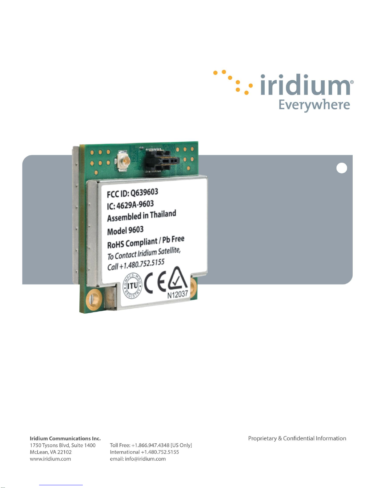
Iridium 9603/9603N
SBD Transceiver Dev el op er’s Guide
RE VI SI ON 3. 1
Page 2

Iridium 9603 SBD Transceiver Product Developers Guide
2
Revision 3.1
LEGAL DISCLAIMER AND CONDITIONS OF USE
This document contains information for the Iridium 9603/9603N (“Product”) and is provided “as is.”
The purpose of providing such information is to enable Value Added Resellers and Value Added
Manufacturers (collectively, “Product Developer(s)”) to understand the Product and how to
integrate it into a wireless solution. Reasonable effort has been made to make the information in
this document reliable and consistent with specifications, test measurements and other
information. However, Iridium Communications Inc. and its affiliated companies, directors, officers,
employees, agents, trustees or consultants (“Iridium”) assume no responsibility for any
typographical, technical, content or other inaccuracies in this document. Iridium reserves the right
in its sole discretion and without notice to you to change Product specifications and materials
and/or revise this document or withdraw it at any time. This document is provided in conjunction
with the purchase of the Product and is therefore subject to the Product Sales Terms and
Conditions set forth at http://www.Iridium.com/support/library/Legal Notices.aspx. The Product
Developer assumes any and all risk of using the Product specifications and any other information
provided.
Your use of this document is governed by your Partner Agreement with Iridium. Please review
your Partner Agreement and the Iridium Product Sales Terms and Conditions that govern your
relationship with Iridium. This document is strictly Proprietary and Confidential to Iridium.
Consistent with your Partner Agreement with Iridium, you may not this document (or any portion
thereof) to others without express written permission from Iridium. Any violation of your
Agreement's Proprietary and Confidentiality obligations shall result in remedies to the fullest
extent available to Iridium at law or in equity.
IRIDIUM MAKES NO REPRESENTATIONS, GUARANTEES, CONDITIONS OR WARRANTIES,
EITHER EXPRESS OR IMPLIED, INCLUDING WITHOUT LIMITATION, ANY IMPLIED
REPRESENTATIONS, GUARANTEES, CONDITIONS OR WARRANTIES OF
MERCHANTABILITY AND FITNESS FOR A PARTICULAR PURPOSE, NON-INFRINGEMENT,
SATISFACTORY QUALITY, NON-INTERFERENCE, ACCURACY OF INFORMATIONAL
CONTENT, OR ARISING FROM A COURSE OF DEALING, LAW, USAGE, OR TRADE
PRACTICE, USE, OR RELATED TO THE PERFORMANCE OR NONPERFORMANCE OF ANY
PRODUCTS AND/OR SERVICES ACCESSORIES, FACILITIES OR SATELLITE SERVICES OR
INFORMATION EXCEPT AS EXPRESSLY STATED IN THIS DOCUMENT AND/OR THE
PRODUCT AND/OR SATELLITE SERVICE DOCUMENTATION. ANY OTHER STANDARDS
OF PERFORMANCE, GUARANTEES, CONDITIONS AND WARRANTIES ARE HEREBY
EXPRESSLY EXCLUDED AND DISCLAIMED TO THE FULLEST EXTENT PERMITTED BY
LAW. THIS DISCLAIMER AND EXCLUSION SHALL APPLY EVEN IF THE EXPRESS
LIMITED WARRANTY CONTAINED IN SUCH DOCUMENTATION FAILS OF ITS ESSENTIAL
PURPOSE.
IN NO EVENT SHALL IRIDIUM BE LIABLE, REGARDLESS OF LEGAL THEORY, INCLUDING
WITHOUT LIMITATION CONTRACT, EXPRESS OR IMPLIED WARRANTY, STRICT
LIABILITY, GROSS NEGLIGENCE OR NEGLIGENCE, FOR ANY DAMAGES IN EXCESS OF
THE PURCHASE PRICE OF THIS DOCUMENT, IF ANY. NOR SHALL IRIDIUM BE LIABLE
FOR ANY DIRECT, INDIRECT, INCIDENTAL, SPECIAL OR CONSEQUENTIAL DAMAGES OF
ANY KIND, OR LOSS OF REVENUE OR PROFITS, LOSS OF BUSINESS, LOSS OF PRIVACY,
LOSS OF USE, LOSS OF TIME OR INCONVENIENCE, LOSS OF INFORMATION OR DATA,
Proprietary & Confidential Information
Distribution of guide restricted to product developers only • Information contained in this guide is subject to change without notice.
Page 3

Iridium 9603 SBD Transceiver Product Developers Guide
3
Revision 3.1
SOFTWARE OR APPLICATIONS OR OTHER FINANCIAL LOSS CAUSED BY THE
PRODUCT/SERVICE (INCLUDING HARDWARE, SOFTWARE AND/OR FIRMWARE) AND/OR
THE IRIDIUM SATELLITE SERVICES, OR ARISING OUT OF OR IN CONNECTION WITH THE
ABILITY OR INABILITY TO USE THE PRODUCT/SERVICE (INCLUDING HARDWARE,
SOFTWARE AND/OR FIRMWARE) AND/OR THE IRIDIUM SATELLITE SERVICES TO THE
FULLEST EXTENT THESE DAMAGES MAY BE DISCLAIMED BY LAW AND WHETHER
ADVISED OF THE POSSIBILITIES OF SUCH DAMAGES. IRIDIUM IS NOT LIABLE FOR ANY
CLAIM MADE BY A THIRD PARTY OR MADE BY YOU FOR A THIRD PARTY.
Your use of the information contained in this Guide is restricted to the development
activity authorized under the agreement(s) between you and Iridium, and is otherwise
subject to all applicable terms and conditions of such agreement(s), including without
limitation software license, warranty, conditions of use and confidentiality provisions.
Export Compliance Information
This Product is controlled by the export laws and regulations of the United States of America. The
U.S. Government may restrict the export or re-export of this Product to certain individuals and/or
destinations. Diversion contrary to U.S. law is prohibited. For further information, contact the U.S.
Department of Commerce, Bureau of Industry and Security or visit www.bis.doc.gov.
Proprietary & Confidential Information
Distribution of guide restricted to product developers only • Information contained in this guide is subject to change without notice.
Page 4

Iridium 9603 SBD Transceiver Product Developers Guide
4
Revision
Date
Comment
.9
05-09-12
Iridium 9603 Initial Release
1.0
06-04-12
Iridium Commercial Release
2.0
08-06-12
Added Section 4.2.2 addressing antennae design guidance.
3.0
08-22-14
Updated to include 9603N
3.1
08-26-14
Updated FCC and IC regulatory statements based on guidance from BABT
Revision 3.1
Revision History
Proprietary & Confidential Information
Distribution of guide restricted to product developers only • Information contained in this guide is subject to change without notice.
Page 5

Iridium 9603 SBD Transceiver Product Developers Guide
5
Revision 3.1
Revision History ....................................................................................................................... 4
List of Abbreviations ................................................................................................................ 6
1 Product Overview ................................................................................................................. 7
1.1 Key Features ............................................................................................................................................................. 7
1.2 Transceiver Regulatory Certification.......................................................................................................................... 8
1.3 Software Revision...................................................................................................................................................... 9
1.4 Unauthorised Changes .............................................................................................................................................. 9
1.5 Radio Interference ..................................................................................................................................................... 9
1.6 RF Exposure ............................................................................................................................................................. 9
1.7 FCC Class B Digital Device Notice .......................................................................................................................... 10
1.8 Labelling Requirements for the Host device ............................................................................................................ 10
1.9 CAN ICES-3 (B) / NMB-3 (B) ................................................................................................................................... 10
1.10 R&TTE Statement ................................................................................................................................................... 11
2 Physical Specification ........................................................................................................ 12
2.1 Module Dimensions ................................................................................................................................................. 12
2.2 Mechanical Dimensions – Motherboard Mounting ................................................................................................... 14
2.3 Environmental ......................................................................................................................................................... 17
2.3.1 Environmental Specification .................................................................................................................................... 17
2.3.2 Environmental Tests Performed .............................................................................................................................. 17
2.4 Physical Interface Connectors ................................................................................................................................. 17
3 Electrical Interfaces ............................................................................................................ 18
3.1 User Connector ....................................................................................................................................................... 18
3.1.1 User Connector Type .............................................................................................................................................. 18
3.1.2 User Connector Pin Allocation ................................................................................................................................. 19
3.2 DC Power Interface ................................................................................................................................................. 20
3.2.1 Power On/Off Control ................................................................................................................................ .............. 22
3.2.2 Typical Power Usage Profile ................................................................................................................................... 22
3.3 Serial Data Interface ................................................................................................................................................ 23
3.4 Network Available Output ........................................................................................................................................ 23
3.5 DC Supply Indicator Output ................................................................................................................................ ..... 23
4 RF Interface ......................................................................................................................... 24
4.1 RF Connector .......................................................................................................................................................... 24
4.2 Antenna Implementation .......................................................................................................................................... 24
4.2.1 Antenna Characteristics .......................................................................................................................................... 24
4.2.2 Important Design Guidance for the 9603 ................................................................................................................. 24
4.3 RF Interface Specifications ...................................................................................................................................... 25
4.4 Radio Characteristics ........................................................................................................................................ 25
4.5 S-meter Performance ................................................................................................................................ .............. 25
5 AT Command Set Description ............................................................................................ 25
Proprietary & Confidential Information
Distribution of guide restricted to product developers only • Information contained in this guide is subject to change without notice.
Page 6

Iridium 9603 SBD Transceiver Product Developers Guide
6
Abbreviation
Description
CE
Conformité Européene
CTS
(V.24 signal) Clear To Send. This signal is used to control the flow of data to the Iridium 9603/9603N
DC
Direct Current
DCD
(V.24 signal) Data Carrier Detect
DCE
Data Communications Equipment. In this Product, DCE refers to the Iridium 9603/9603N
DSR
(V.24 signal) Data Set Ready. This signal, from the Iridium 9603/9603N, indicates readiness to accept
communication over the data port
DTE
Data Terminal Equipment. In this Product, DTE refers to the FA
DTR
(V.24 signal) Data Terminal Ready. This signal, from the FA, requests the Iridium 9603/9603N to accept
communication over the data port
ESS
ETC SBD Subsystem (synonymous with GSS)
ETC
Earth Terminal Controller
FA
Field Application; the application controlling the Iridium 9603/9603N
FCC
Federal Communications Commission
GND
Ground
GSS
Gateway SBD Subsystem (synonymous with ESS)
IC
Industry Canada
IMEI
International Mobile Equipment Identity
LBT
L-Band Transceiver
MO
Mobile Originated
MOMSN
Mobile Originated Message Sequence Number
MT
Mobile Terminated
MTMSN
Mobile Terminated Message Sequence Number
RHCP
Right Hand Circular Polarization
RI
(V.24 signal) Ring Indicate. This signal, from the Iridium 9603/9603N, indicates that an MT message is present
at the GSS
RTS
(V.24 signal) Request To Send. This signal is used to control the flow of data from the Iridium 9603/9603N.
SBD
Short Burst Data
SMS
Short Message Service
TBA
To Be Advised
UART
Universal Asynchronous Receiver Transmitter
VAM
Value Added Manufacturer
VAR
Value Added Reseller
VSWR
Voltage Standing Wave Ratio
Revision 3.1
List of Abbreviations
Proprietary & Confidential Information
Distribution of guide restricted to product developers only • Information contained in this guide is subject to change without notice.
Page 7

Iridium 9603 SBD Transceiver Product Developers Guide
7
Revision 3.1
1 Product Overview
The Iridium 9603/9603N Short Burst Data Only Transceiver (9603/9603N) is designed to be integrated into a wireless data
application with other host system hardware and software to produce a full solution designed for a specific application or vertical
market. Examples of these solutions include tracking a maritime vessel or automatic vehicle location.
The 9603/9603N only supports Iridium’s Short Burst Data (SBD) capability. It does not support voice, circuit
switched data, or short message service (SMS).
The 9603/9603N is designed to meet the regulatory requirements for approval for FCC, Canada, and CE assuming an antenna
with a gain of ~3 dBi and adequate shielding. This allows the 9603/9603N to be integrated into a variety of wireless data
applications or retrofitted into existing SBD-only applications that utilize SBD with the current Iridium 9602, 9601, 9522A, 9522B or
9522 L-Band transceiver-based products. (Note that additional development work will be required). Such finished products, when
integrated together, require regulatory and safety testing to be conducted by the integrator.
The 9603/9603N is a single board transceiver provided as a ‘black box’ transceiver module with all device interfaces provided by a
single multi-pin interface connector in addition to the antenna connector. The Product only provides the core transceiver. All other
end user Field Application functions such as GPS, microprocessor based logic control, digital and analog inputs, digital and analog
outputs, power supply and antenna must be provided by the solution developer. The device interface across the user connector
consists of a serial-data interface, DC power input, network available output and a power on/off control line.
The 9603/9603N does not incorporate nor require a Subscriber Identity Module (also known as a SIM Card) to be inserted into the
Transceiver. The 9603/9603N is intended to be used as a transceiver module fitted within another host system. The 9603/9603N
module is designed to comply with the standards for Radio Emissions Compliance, Electromagnetic Compatibility, and AC Safety
in the United States, European Union and Canada, for host systems that provide safe connections to power supply and external
antenna or cable distribution system.
The 9603N is a second generation version of the 9603 and is identical in form and function to the 9603. This document applies to
both the 9603 and 9603N as indicated by the term ‘9603/9603N’. Where the contents of this document apply specifically to either
the 9603 or 9603N then this is indicated by the use of the terms ‘9603’ and ‘9603N’ respectively.
The Iridium 9603/9603N is described within this document as “Iridium 9603/9603N”, “9603/9603N SBD Transceiver”, “Modem,” and
“ISU.” All of these terms refer to the same product.
1.1 Key Features
Single board transceiver
Small form factor
No SIM card
Designed to be incorporated into an OEM solution
Maximum mobile originated message size 340 bytes
Maximum mobile terminated message size 270 bytes
Automatic Notification to the Transceiver that a mobile terminated message is queued at the Gateway
Global operating capability
RoHS compliant
Proprietary & Confidential Information
Distribution of guide restricted to product developers only • Information contained in this guide is subject to change without notice.
Page 8
Iridium 9603 SBD Transceiver Product Developers Guide
8
Regulatory
Approvals
Radio Tests
EMC Tests
Electrical / Mechanical /
Operational
Safety Tests
CE
ETSI EN 301 441 V1.1.1
(2000-05)
ETSI EN 301 489-20 V1.2.1 (2002-11)
ETSI EN 301 489-1 V1.8.1 (2008-04)
EN61000-4-2 : 1995/A2 : 2001 Part 4.2
EN61000-4-3 : 2002 Part 4.3
EN61000-4-4 : 2004
EN61000-4-6 : 1996/A1 : 2001 Part 4.6
EN55022:2006
EN60950-1:2006 Part 1
FCC
FCC CFR47 parts 2, 15, and 25
Industry
Canada
Industry Canada RSS170 Issue 2, March, 2011
Regulatory
Approvals
Radio Tests
EMC Tests
Electrical / Mechanical /
Operational
Safety Tests
CE
ETSI EN 301 441 V1.1.1
(2000-05)
ETSI EN 301 489-20 V1.2.1 (2002-11)
ETSI EN 301 489-1 V1.9.2 (2011)
EN61000-4-2 : 2009
EN61000-4-3 : 2006 + A1: 2008 + A2: 2010
EN61000-4-4 : 2004 + A1: 2010
EN61000-4-6 : 2009
EN55022:2006 + A1: 2007
EN60950-1:2006 + A11: 2009 +
A1: 2010 + A12: 2011
FCC
FCC CFR47 parts 2 (2013), 15B (2013), and 25 (2013)
Industry
Canada
Industry Canada RSS170 Issue 2, March, 2011
Industry Canada RSS-GEN Issue 3, December, 2010
Revision 3.1
1.2 Transceiver Regulatory Certification
The 9603/9603NSBD Transceiver is a regulatory approved daughter module transceiver that can be fitted within an enclosed host
system. With appropriate external connections, the host system can be designed to meet full transceiver regulatory tests and sold
as a Regulatory Certified product that meets CE, FCC and IC requirements.
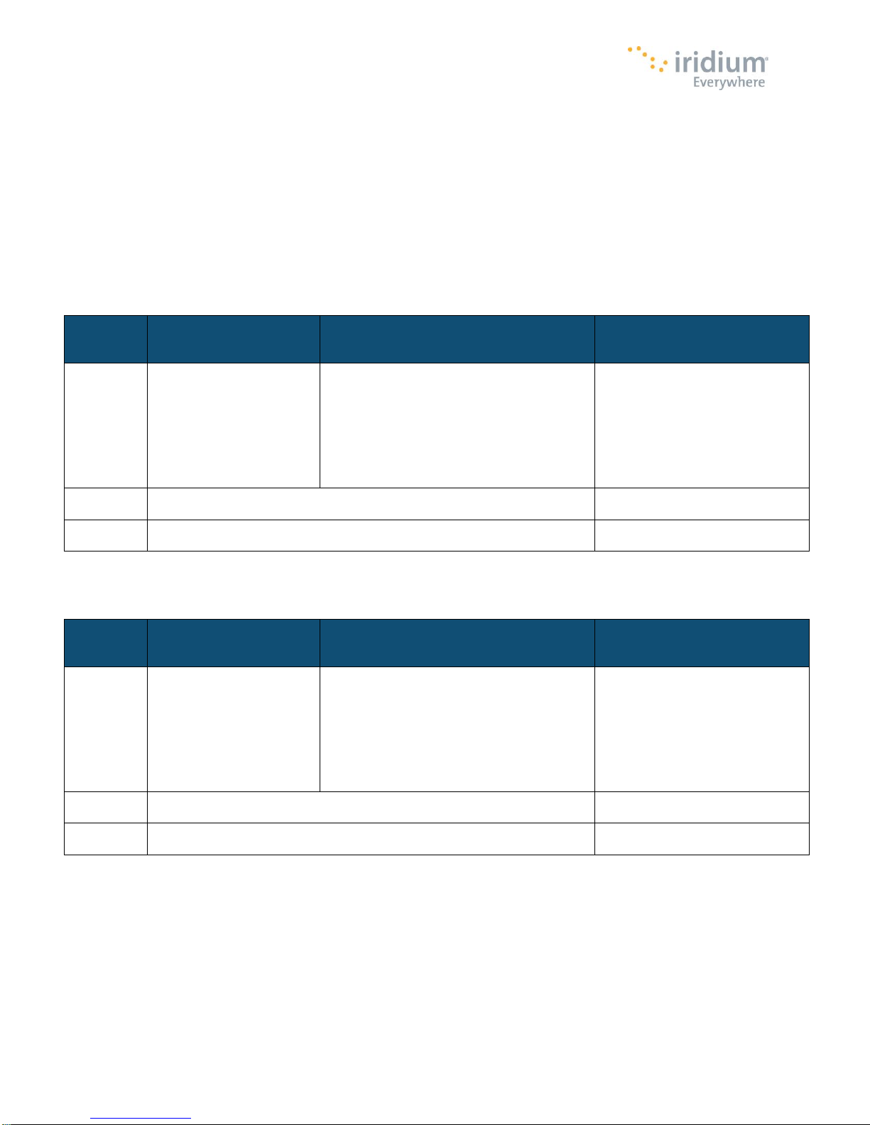
The 9603 has regulatory and technical certifications as shown in Table 1. The 9603N has regulatory and technical certifications as
shown in Table 1a.
Table 1: 9603 Regulatory and Technical Certifications.
Table 1a: 9603N Regulatory and Technical Certifications.
Note: The OEM integrator is responsible for ensuring that their end-product complies with additional compliance requirements
required with this module installed, such as digital device/unintentional emissions requirements and any additional potential RF
Exposure requirements, such as portable use or co-location requirements.
Proprietary & Confidential Information
Distribution of guide restricted to product developers only • Information contained in this guide is subject to change without notice.
Page 9

Iridium 9603 SBD Transceiver Product Developers Guide
9
Revision 3.1
1.3 Software Revision
Product Developers should read this document in conjunction with the “Software Release Notes” relevant to the revision of the
software that is loaded into their Iridium 9603/9603N SBD Transceiver.
Product Developers should take into account in their software design that it is possible that a transceiver may have an earlier
software release and may therefore have different capabilities to those listed in this document. Product Developers are advised to
ensure that production procedures for finished goods confirm that the software used in the Product Developer application is
designed for the Software Release loaded in the Iridium 9603/9603N SBD Transceiver. This can be read out of the module using
the AT command interface. A software upgrade utility is provided with each SW release. The utility runs on a Windows compatible
OS and will automatically upgrade the modem with the latest version.
1.4 Unauthorised Changes
Iridium has not approved any changes or modifications to this device by the user. Any changes or modifications could void the
user’s authority to operate the equipment.
Iridium n’approuve aucune modification apportée à l’appareil par l’utilisateur, quelle qu’en soit la nature. Tout changement ou
modification peuvent annuler le droit d’utilisation de l’appareil par l’utilisateur.
1.5 Radio Interference
This device complies with Part 15 of the FCC Rules and Industry Canada licence-exempt RSS standard(s). Operation is subject to
the following two conditions: (1) this device may not cause interference, and (2) this device must accept any interference, including
interference that may cause undesired operation of the device.
Under Industry Canada regulations, this radio transmitter may only operate using an antenna of a type and maximum (or lesser)
gain approved for the transmitter by Industry Canada. To reduce potential radio interference to other users, the antenna type and
its gain should be so chosen that the equivalent isotropically radiated power (EIRP) is not more than that necessary for successful
communication.
Le présent appareil est conforme aux CNR d'Industrie Canada applicables aux appareils radio exempts de licence. L'exploitation
est autorisée aux deux conditions suivantes : (1) l'appareil ne doit pas produire de brouillage, et (2) l'utilisateur de l'appareil doit
accepter tout brouillage radioélectrique subi, même si le brouillage est susceptible d'en compromettre le fonctionnement.
Conformément à la réglementation d'Industrie Canada, le présent émetteur radio peut fonctionner avec une antenne d'un type et
d'un gain maximal (ou inférieur) approuvé pour l'émetteur par Industrie Canada. Dans le but de réduire les risques de brouillage
radioélectrique à l'intention des autres utilisateurs, il faut choisir le type d'antenne et son gain de sorte que la puissance isotrope
rayonnée équivalente (PIRE) ne dépasse pas l'intensité nécessaire à l'établissement d'une communication satisfaisante.
1.6 RF Exposure
This equipment complies with FCC and IC radiation exposure limits set forth for an uncontrolled environment. The antenna should
be installed and operated with minimum distance of 20 cm between the radiator and your body. Antenna gain must be below: 3.0
dBi. This transmitter must not be co-located or operating in conjunction with any other antenna or transmitter.
Cet appareil est conforme aux limites d'exposition aux rayonnements de la IC pour un environnement non contrôlé. L'antenne doit
être installé de façon à garder une distance minimale de 20 centimètres entre la source de rayonnements et votre corps. Gain de
l'antenne doit être ci-dessous: 3.0 dBi. L'émetteur ne doit pas être colocalisé ni fonctionner conjointement avec à autre antenne ou
autre émetteur.
Proprietary & Confidential Information
Distribution of guide restricted to product developers only • Information contained in this guide is subject to change without notice.
Page 10

Iridium 9603 SBD Transceiver Product Developers Guide
10
Revision 3.1
1.7 FCC Class B Digital Device Notice
This equipment has been tested and found to comply with the limits for a Class B digital device, pursuant to part 15 of the FCC
Rules. These limits are designed to provide reasonable protection against harmful interference in a residential installation. This
equipment generates, uses and can radiate radio frequency energy and, if not installed and used in accordance with the
instructions, may cause harmful interference to radio communications. However, there is no guarantee that interference will not
occur in a particular installation. If this equipment does cause harmful interference to radio or television reception, which can be
determined by turning the equipment off and on, the user is encouraged to try to correct the interference by one or more of the
following measures:
- Reorient or relocate the receiving antenna.
- Increase the separation between the equipment and receiver.
- Connect the equipment into an outlet on a circuit different from that to which the receiver is connected.
- Consult the dealer or an experienced radio/TV technician for help.
1.8 Labelling Requirements for the Host device
The host device shall be properly labelled to identify the modules within the host device. The certification label of the module shall
be clearly visible at all times when installed in the host device, otherwise the host device must be labelled to display the FCC ID
and IC of the module, preceded by the words "Contains transmitter module", or the word "Contains", or similar wording expressing
the same meaning, as follows:
Contains FCC ID: Q639603N or Contains transmitter module FCC ID: Q639603N
Contains IC: 4629A-9603N or Contains transmitter module IC: 4629A-9603N
L'appareil hôte doit être étiqueté comme il faut pour permettre l'identification des modules qui s'y trouvent. L'étiquette de
certification du module donné doit être posée sur l'appareil hôte à un endroit bien en vue en tout temps. En l'absence d'étiquette,
l'appareil hôte doit porter une étiquette donnant le FCC ID et le IC du module, précédé des mots « Contient un module d'émission
», du mot « Contient » ou d'une formulation similaire exprimant le même sens, comme suit:
Contains FCC ID: Q639603N or Contains transmitter module FCC ID: Q639603N
Contains IC: 4629A-9603N or Contains transmitter module IC: 4629A-9603N
1.9 CAN ICES-3 (B) / NMB-3 (B)
This Class B digital apparatus complies with Canadian ICES-003.
Cet appareil numérique de classe B est conforme à la norme canadienne ICES-003.
Proprietary & Confidential Information
Distribution of guide restricted to product developers only • Information contained in this guide is subject to change without notice.
Page 11
Iridium 9603 SBD Transceiver Product Developers Guide
11
Revision 3.1
1.10 R&TTE Statement
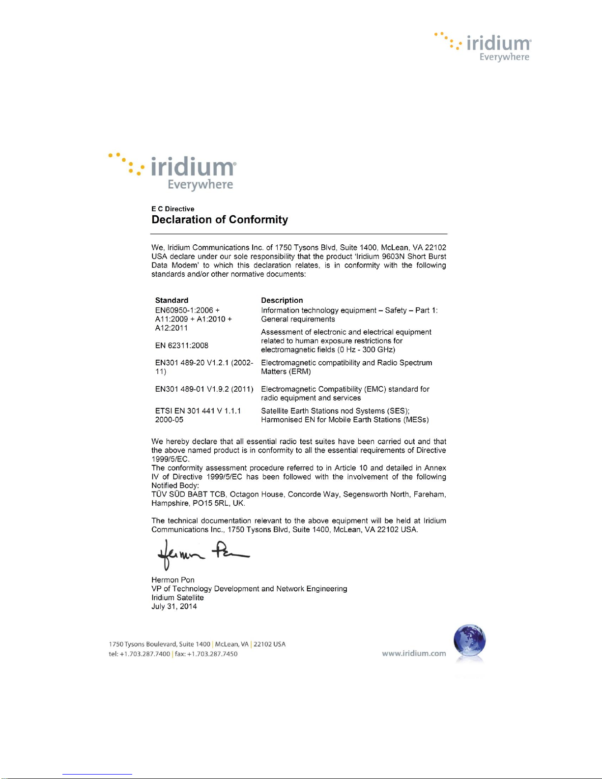
Iridium Communications Inc. hereby declares that the 9603N is in compliance with the essential requirements and other relevant
provisions of Directive1999/5/EC. A copy of the Declaration of Conformity is given below.
Proprietary & Confidential Information
Distribution of guide restricted to product developers only • Information contained in this guide is subject to change without notice.
Page 12
Iridium 9603 SBD Transceiver Product Developers Guide
12
Parameter
Value
Length
31.5 mm
Width
29.6 mm
Depth
8.10 mm
Weight (approximate)
11.4g
Revision 3.1
2 Physical Specification
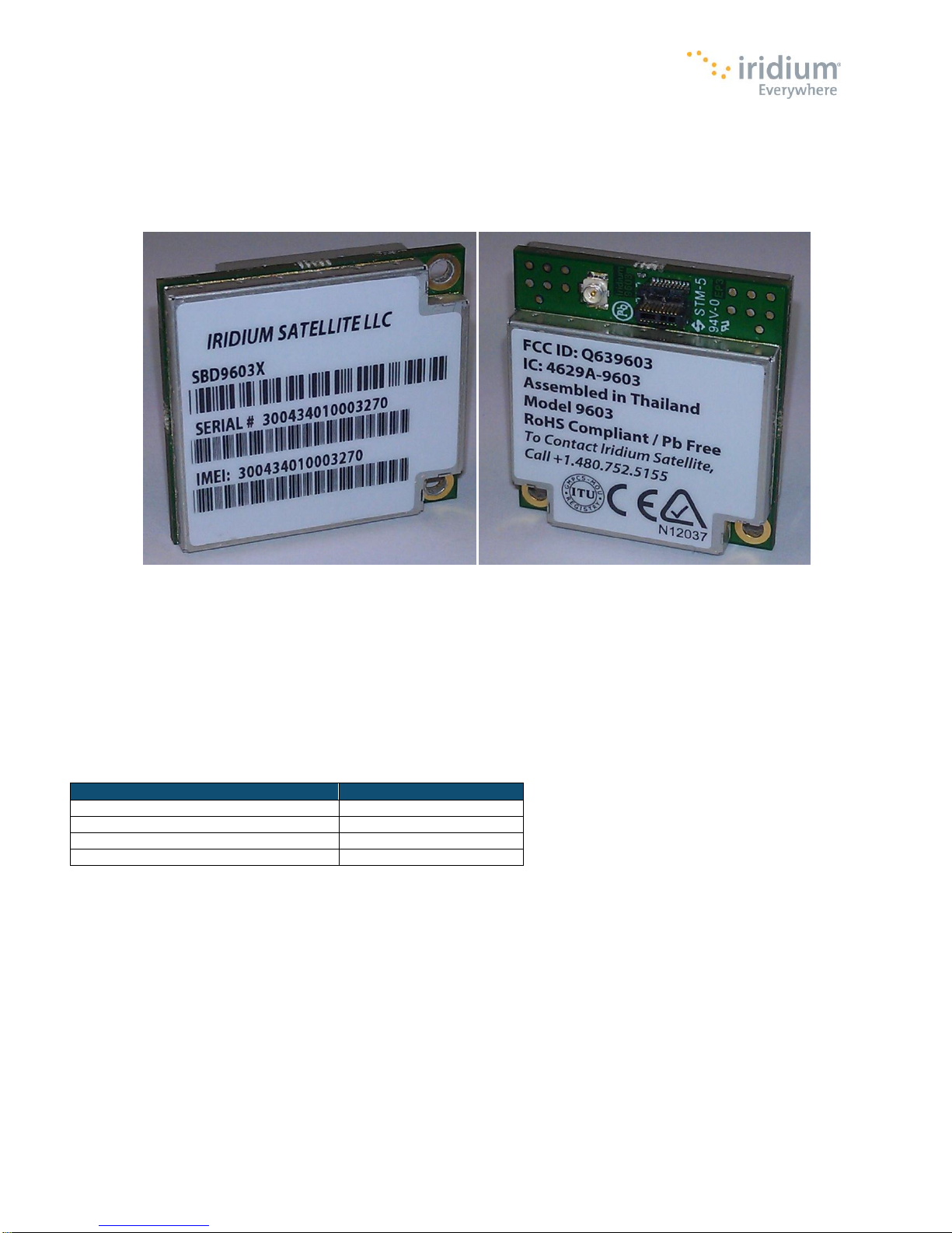
For illustrative purposes a picture of the Iridium 9603 SBD Transceiver Module* is shown in Figure 1.
Figure 1. Iridium 9603 SBD Transceiver Front and Back Views
*Note: The appearance of the 9603N is identical to the 9603 with the exception of the part marking on the label.
2.1 Module Dimensions
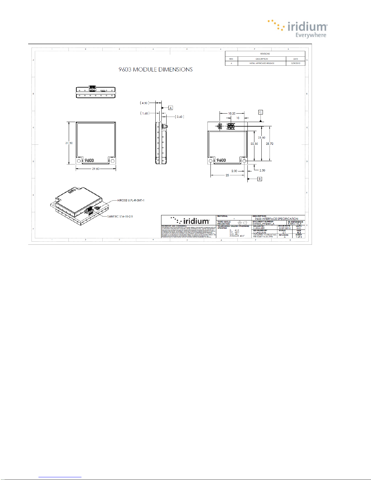
The overall dimensions of the Iridium 9603/9603N module and its weight are summarized in Table 2. These figures are approximate
and are expected to change in the next revision.
Table 2: Iridium 9603/9603N Mechanical Dimensions and Weight
These dimensions are subject to change for future revisions
Additionally host system Product Developers should plan space for connection to the host system motherboard, including robust
and electrically grounded connections to the antenna/cable distribution system.
Proprietary & Confidential Information
Distribution of guide restricted to product developers only • Information contained in this guide is subject to change without notice.
Page 13
Iridium 9603 SBD Transceiver Product Developers Guide
13
Revision 3.1
Figure 2. Dimensions of the 9603/9603N Transceiver
Proprietary & Confidential Information
Distribution of guide restricted to product developers only • Information contained in this guide is subject to change without notice.
Page 14
Iridium 9603 SBD Transceiver Product Developers Guide
14
Revision 3.1
2.2 Mechanical Dimensions – Motherboard Mounting
The Iridium 9603/9603N SBD Transceiver must be fitted within an enclosed host system. With appropriate external connections,
the host system motherboard and host system enclosure can be designed to meet full transceiver regulatory tests.
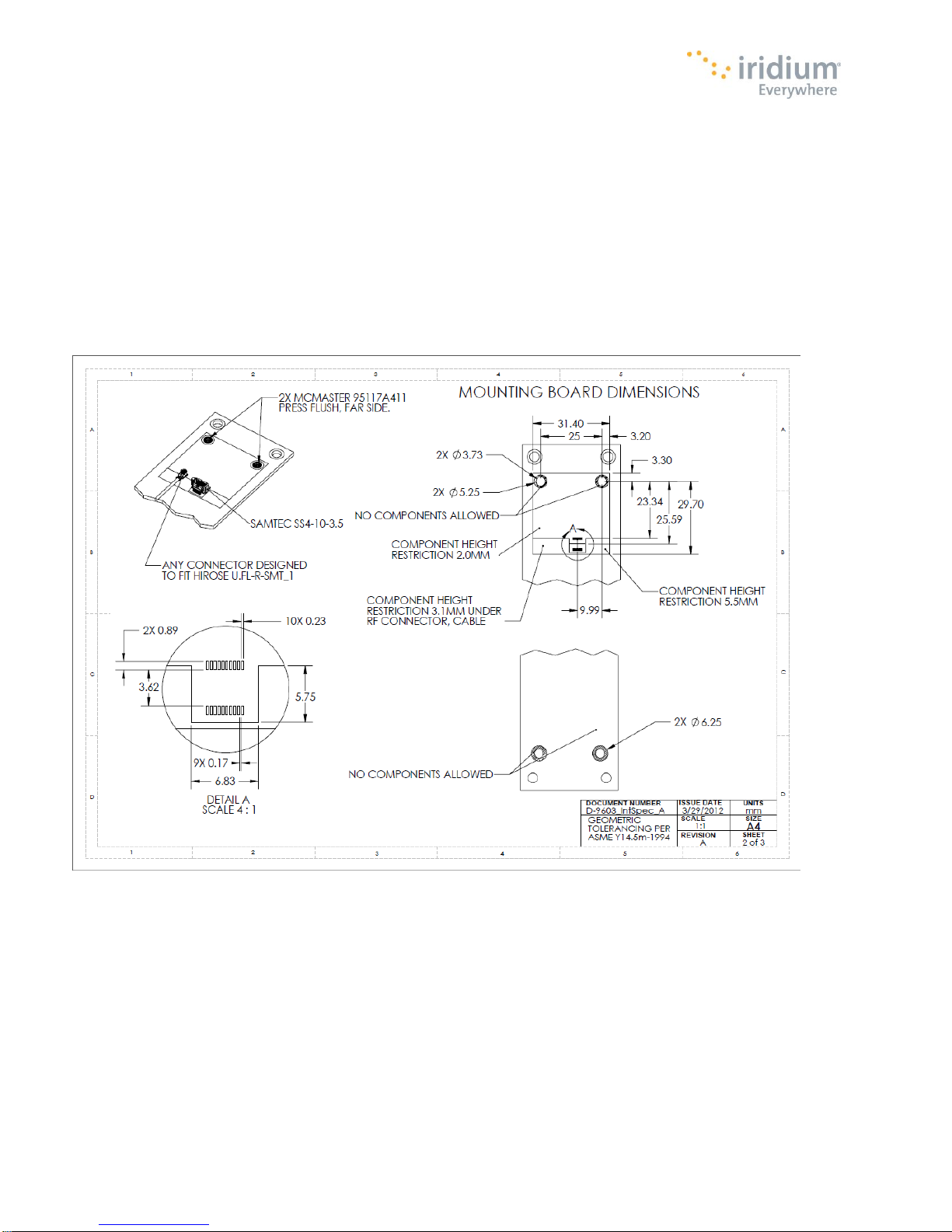
The Iridium 9603/9603N SBD Transceiver is provided with two mounting holes on the opposite side from the system connector.
The module should be assembled onto the motherboard of the host system, by pushing the module onto matching connectors on
the motherboard and then securing the two mounting holes to the motherboard using screws.
Figure 3. Motherboard mounting for the 9603/9603N Transceiver
Proprietary & Confidential Information
Distribution of guide restricted to product developers only • Information contained in this guide is subject to change without notice.
Page 15
Iridium 9603 SBD Transceiver Product Developers Guide
15
Revision 3.1
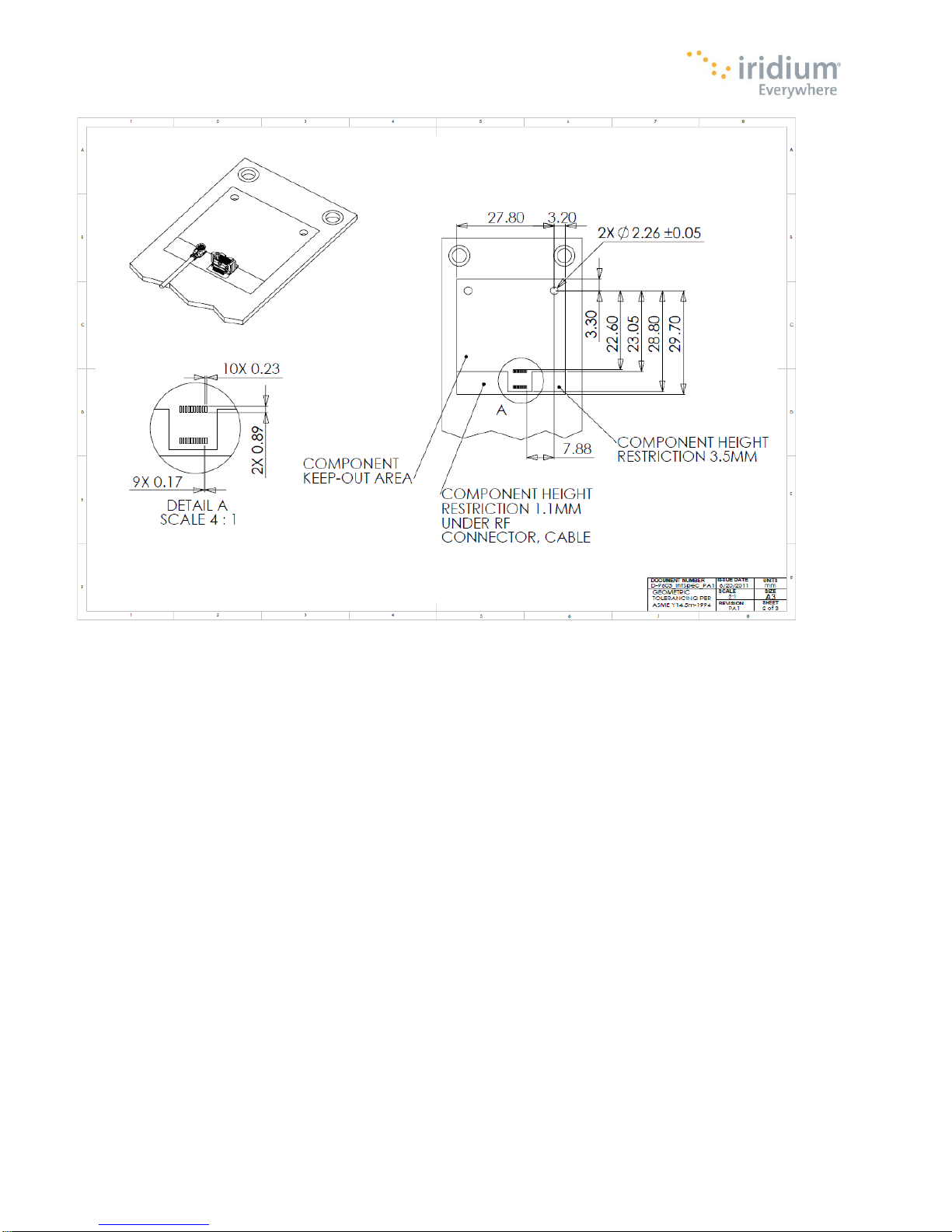
Figure 4. Connector and Mounting Detail for the Iridium 9603/9603N Transceiver
Proprietary & Confidential Information
Distribution of guide restricted to product developers only • Information contained in this guide is subject to change without notice.
Page 16
Iridium 9603 SBD Transceiver Product Developers Guide
16
Revision 3.1
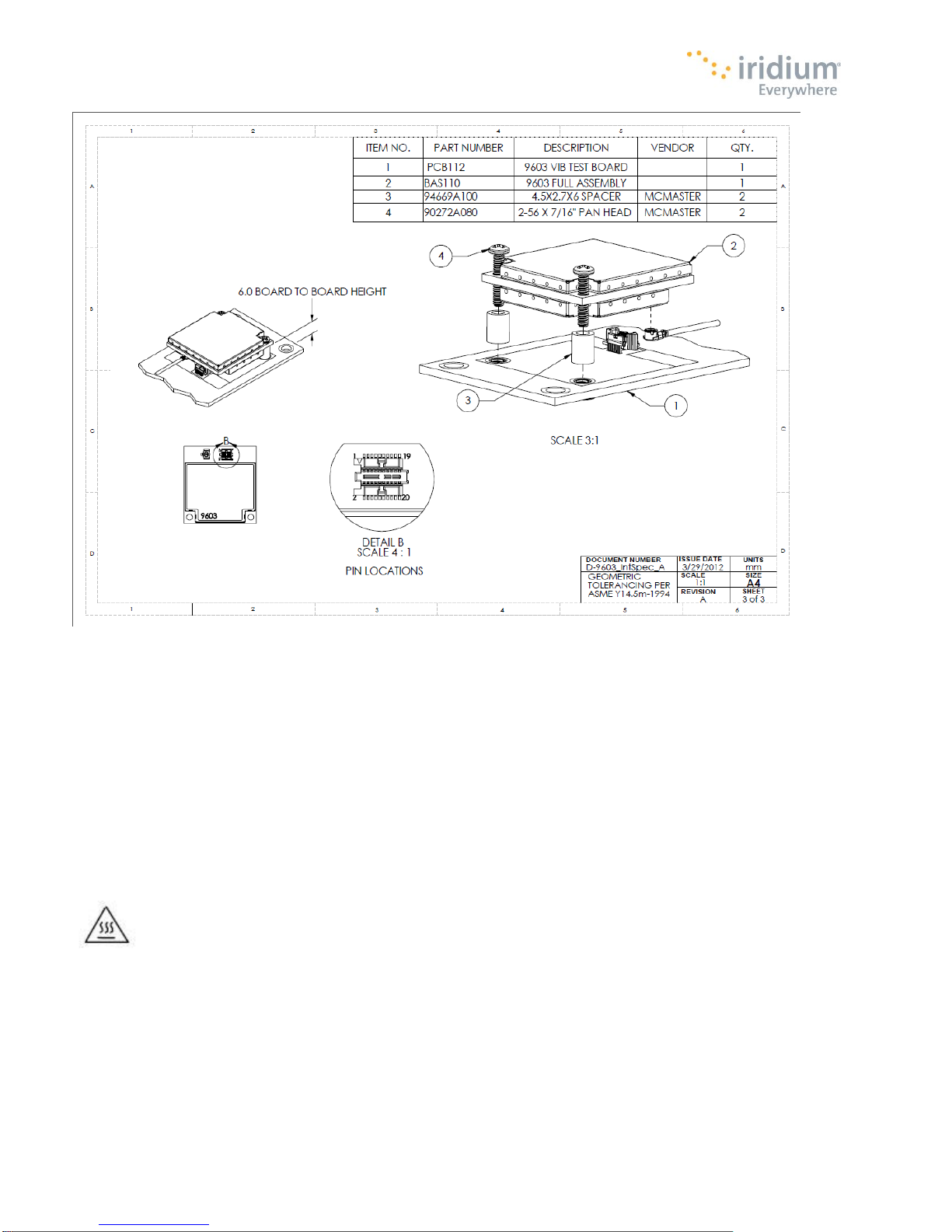
Figure 5. Motherboard mounting suggestions for the 9603/9603N Transceiver
1. This example of a host system motherboard footprint is shown for illustrative purposes only. The host system may require a
different PCB layout or mechanical arrangement.
2. The 9603/9603N is designed to be incorporated within a host system. As such, the antenna or cable distribution system that
feeds the host system should be terminated in a robust RF connector that is suitable for the end-application.
3. Safety isolation requirements for external antennas or cable distribution systems should also be taken into consideration when
designing the motherboard. A suitably safe design for the RF connections should be incorporated into the host system
motherboard, ideally using a chassis-bonded ground connection to the antenna cable shield.
4. The surface below the modem should be a conductive ground plane such that the modem bonds to the motherboard ground
system thus reducing the possibility of radiated emissions. This also requires that the mounting screws be properly tightened
to 10 cNm of torque.
5. The modem is to be installed in a “service access only” area not accessible by untrained personnel.
Warning- Although the modem dissipates very little power, its use in ambient temperatures in excess of 60
degrees C will make the caseworks considerably hot.
Proprietary & Confidential Information
Distribution of guide restricted to product developers only • Information contained in this guide is subject to change without notice.
Page 17
Iridium 9603 SBD Transceiver Product Developers Guide
17
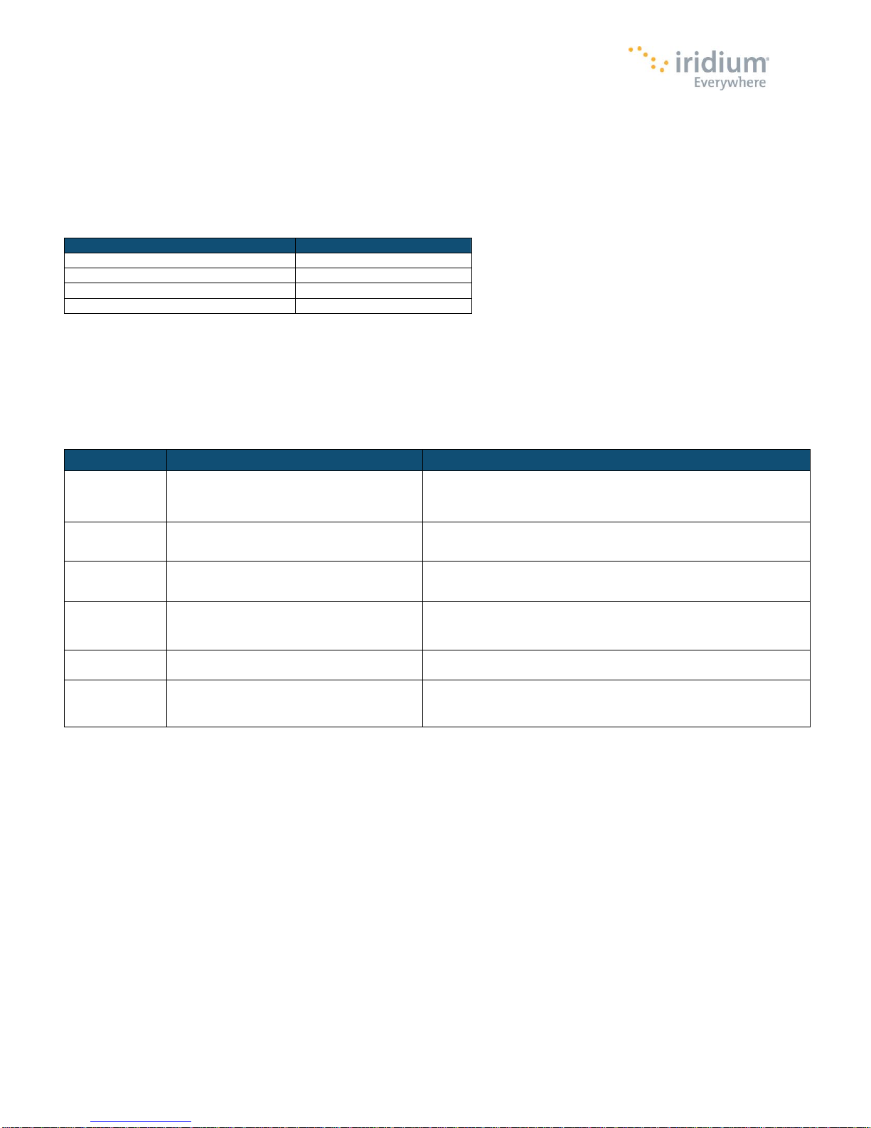
Parameter
Value
Operating Temperature Range*
-30ºC to + 85ºC
Operating Humidity Range
≤ 75% RH
Storage Temperature Range
-40ºC to + 85ºC
Storage Humidity Range
≤ 93% RH
Test Name
Test Reference
Test Description
Thermal Shock
EN60068-2-14:2009
Change of Temperature,
-25°C to +70°C,
5 cycles of 1 hour each
Humidity
IEC60068-2-78:2002
Damp heat steady state
40OC 93% RH for 4 days
Vibration
IEC60068-2-64: 2008
0.96 m2/s3 from 5Hz to 20Hz
21Hz to 500Hz dropping 6dB per octave
Vibration
SAE J1455: 2012 Section 4.10
10-40Hz at 0.02g2/Hz
40Hz to 500Hz dropping 6dB per octave
Shock
EN60068-2-27: 2009
10G peak shock over a period of 11ms, 3 shocks in 3 perpendicular
orientations
Shock
SAE J1455: 2012 Section 4.11
Society of Automotive Engineers
Drop 1m onto concrete in 3 perpendicular orientations (3 drops)
Revision 3.1
2.3 Environmental
2.3.1 Environmental Specification
The environmental specifications of the final Iridium 9603/9603N Transceiver Module are summarized in Table 5 below.
Table 5: Environmental Specifications
* Note: The operating temperature range of the 9603N extends down to -40ºC.
2.3.2 Environmental Tests Performed
The 9603/9603N complies with the specifications listed in Table 6.
Table 6: Environmental Tests
2.4 Physical Interface Connectors
The Iridium 9603/9603N SBD Transceiver incorporates two connectors:
A multiway user connector
An RF antenna connector
Proprietary & Confidential Information
Distribution of guide restricted to product developers only • Information contained in this guide is subject to change without notice.
Page 18

Iridium 9603 SBD Transceiver Product Developers Guide
18
Revision 3.1
3 Electrical Interfaces
The following subsections contain information for the electrical interfaces of the 9603/9603N SBD Transceiver for the non-RF
connections. The RF interfaces are covered in section 4 4.
3.1 User Connector
The user connector provides the following connections to the 9603/9603N module:
DC power supply input
Power on/off control
Serial data interface
Network available output
Supply power indicator output
3.1.1 User Connector Type
The connector on the 9603/9603N is a Samtec low-profile header connector, part number ST4-10-2.50-L-D-P-TR. Data sheets on
these connectors can be found at: http://www.samtec.com
A suitable motherboard female socket that matches this connector is the SAMTEC header part number SS4-10-3.00-L-D-K-TR.
Proprietary & Confidential Information
Distribution of guide restricted to product developers only • Information contained in this guide is subject to change without notice.
Page 19
Iridium 9603 SBD Transceiver Product Developers Guide
19
Pin
No.
Signal Name
Signal direction
(WRT 9603/9603N)
Signal function
Signal level
1
EXT_PWR
Input
Supply
+5 V +/- 0.2 V*
2
EXT_PWR
Input
Supply
+5 V +/- 0.2 V*
3
EXT_GND
Input
Supply return
0 V
4
EXT_GND
Input
Supply return
0 V
5
ON/OFF
Input
On/Off control input
Analog
On: >=2.0V
Off: <=0.5V
6
DF_S_TX
Input
Data port, serial data input
3.3V Digital
7
DF_S_RX
Output
Data port, serial data output
3.3V Digital
8
SIG_GND
Input
Signal ground
0V
9
DF_ DCD
Output
Data port, Data Carrier
Detect
3.3V Digital
10
DF_ DSR
Output
Data port, Data Set Ready
3.3V Digital
11
DF_ CTS
Output
Data port, Clear-to-Send
3.3V Digital
12
DF_RI
Output
Data port, Ring Indicator
3.3V Digital
13
DF_ RTS
Input
Data port, Request-to-Send
3.3V Digital
14
DF_ DTR
Input
Data port, Data Terminal
Ready
3.3V Digital
15
SIG_GND
Input
Signal ground
0V
16
Reserved
17
Reserved
18
SIG_GND
Input
Signal ground
0V
19
NETWORK
AVAILABLE
Output
Signals when the
9603/9603N can see an
available satellite network
3.3V Digital
Available = high
Not available= low
20
SUPPLY_OUT
Output
Supply power indicator
output
+3.3 V
5mA maximum
Parameter
Symbol
Min
Typ
Max
Unit
Input High Voltage
VIH
2.0 5.5
V
Input Low Voltage
VIL
-0.3 0.8
V
Output High Voltage
VOH
2.4
V
Output Low Voltage
VOL
0.4
V
Low Level Output Current
IOL
4.4
mA
High Level Output Current
IOH
5.5
mA
Revision 3.1
3.1.2 User Connector Pin Allocation
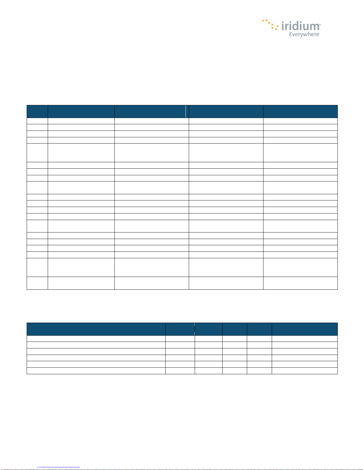
The user connector is surface mount, 0.4mm centerline terminal strip. Individual pin assignments are shown in Table 7 and the
limits for the digital signals are listed in Table 8. Multiple supply grounds are provided and all supply and supply grounds are
required to be connected to the power supply in order to limit the current on any one pin. Multiple signal grounds are provided to
reduce cross-talk.
Table 7: User Connector Pin Allocation
* Note: This is the supply voltage range of the 9603; the 9603N has an extended supply voltage range of +5 V +/- 0.5 V
Table 8: Limits for 3.3V Digital Signals
Proprietary & Confidential Information
Distribution of guide restricted to product developers only • Information contained in this guide is subject to change without notice.
Page 20
Iridium 9603 SBD Transceiver Product Developers Guide
20
Pin 1
Pin 2
Pin 19
Pin 1 is marked on
the connector
Pin 20
Revision 3.1
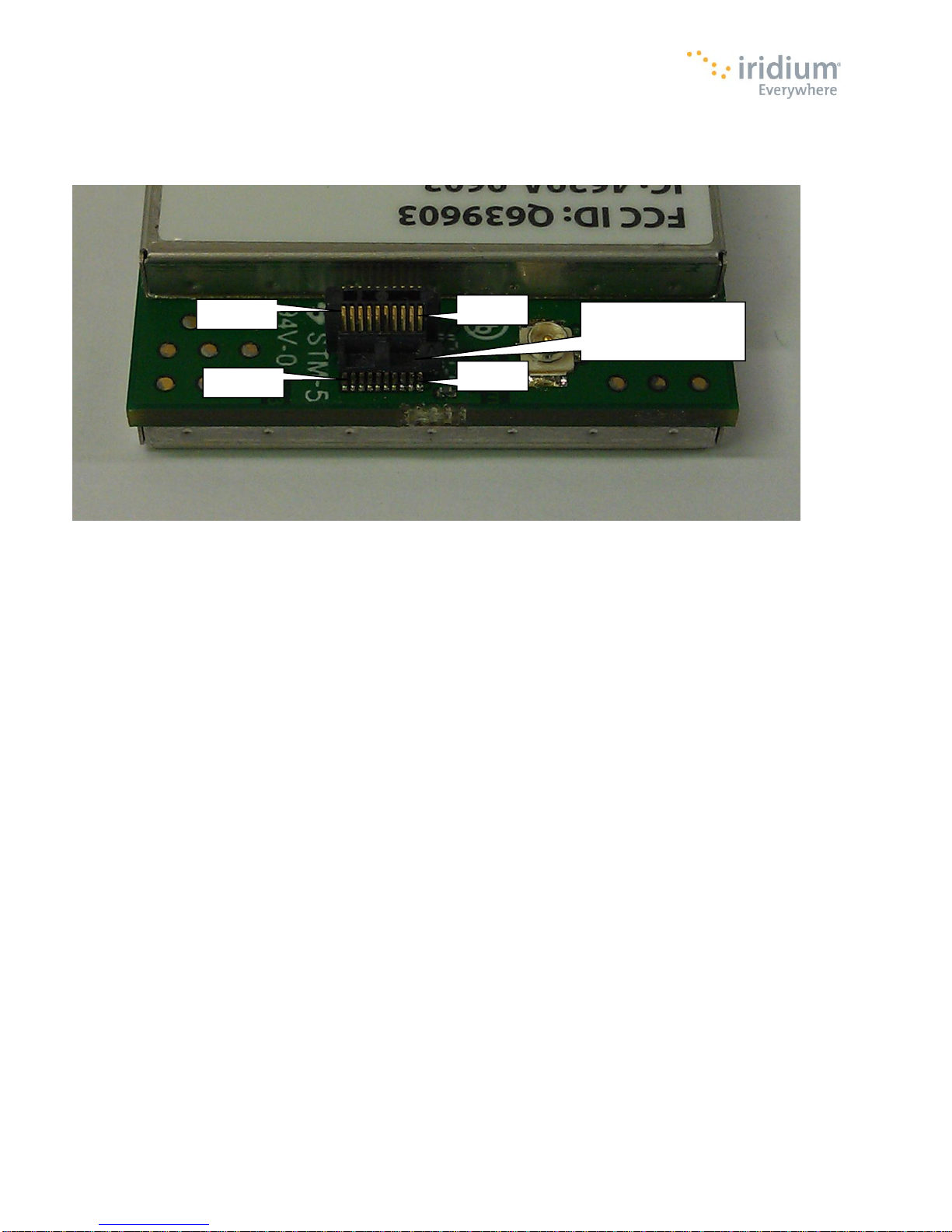
Figure 6 provides a reference for the pin designation. The pins are marked in the figure. Note that Pin 1 is marked on the
connector.
Figure 6. 9603/9603N User Connector Pin Number Designation
3.2 DC Power Interface
The DC power interface is comprised of the DC power inputs and a control signals as summarized in Table 7. The +5V Inputs and
0V supply returns are used to supply DC power to the 9603/9603N and ensure that enough current can be drawn across the
connector without the 9603/9603N malfunctioning during transmit due to lack of current supply. Note that all power and ground
pins should be connected externally.
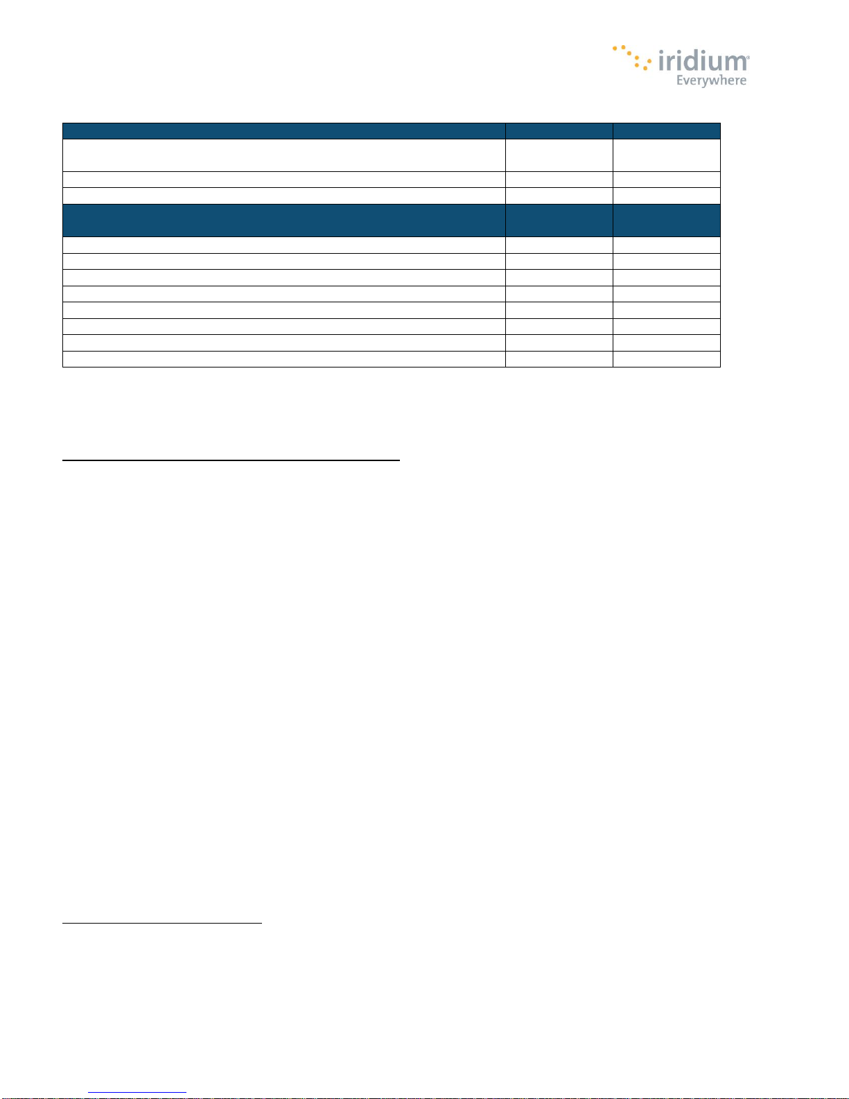
The DC power supply requirements for the 9603/9603N are summarized in Table 9 below. Note that these requirements apply to
DC power measured at the 9603/9603N User connector input and not at the output of the power supply. Long power supply cables
can cause a voltage drop sufficient to cause the voltage to be out of specification at the physical power supply input to the
9603/9603N.
Proprietary & Confidential Information
Distribution of guide restricted to product developers only • Information contained in this guide is subject to change without notice.
Page 21
Iridium 9603 SBD Transceiver Product Developers Guide
21
Parameter
9603 Value
9603N Value
Supply Input Voltage Range
5.0V DC +/-
0.2V**
5.0V DC +/-
0.2V**
Supply Input Voltage Ripple
< 40 mV pp
< 40 mV pp
Typical Power Consumption at +5.0 VDC
9603 Value
9603N Value
Idle Current (average*)
45mA
34mA
Idle Current (peak)
195mA
156mA
Transmit Current (peak)
1.5 A
1.3 A
Transmit Current (average*)
190mA
145mA
Receive Current (peak)
195mA
156mA
Receive Current (average*)
45mA
39mA
SBD message transfer - average current*
190 mA
158mA
SBD message transfer - average power*
<= 1.0 W
<= 0.8 W
1
2
Revision 3.1
Table 9: DC Power Input Specifications
* Note: The average power consumption will vary depending on the view of the satellite constellation from the antenna.
** Note: Includes Tx Burst droop. This is the supply voltage range of the 9603; the 9603N has an extended supply voltage range of
+5 V +/- 0.5 V
The external power supply needs to guarantee the following:
The supply voltage droop over for a 8.3ms burst of 1.5A current should not be more than 0.2 Volts1.
The power supply should limit the in-rush2 current to 4 Amps maximum
The power source shall provide for over current protection in case of device malfunction.
The supply noise should be less than the limits in the following profile:
100 mVpp from 0 to 50 kHz
5 mVpp at 1 MHz measured in 50 kHz bandwidth
10 mVpp at 1 MHz measured in 1MHz bandwidth
5 mVpp above 5 MHz measured in 1 MHz bandwidth.
On the 9603N the supply droop should not be more than 0.5 volts.
In rush limit refers to the impedance of the modem when it is unpowered is very low. When power is supplied from an
unlimited supply the instantaneous current can exceed 4 Amps If the current exceeds this value damage can occur. This can be
limited in several ways, included using a supply that cannot provide more than 4 Amps instantaneously; or providing some
series inductance/resistance to the supply lead.
Proprietary & Confidential Information
Distribution of guide restricted to product developers only • Information contained in this guide is subject to change without notice.
Page 22

Iridium 9603 SBD Transceiver Product Developers Guide
22
Revision 3.1
3.2.1 Power On/Off Control
An external on/off input is provided on a pin of the User connector. The 9603/9603N starts up when power is applied and the
power on/off input is high. As long as the input voltage is applied, logic high on this line turns the transceiver on and a logic low
turns it off. If this line is not required then it must be connected directly to the +5 V supply.
Note that this on/off control is similar to the Iridium 9601 and 9602 products, but it is not the same as the 9522, 9522A or 9522B
products.
Prior to turning off the modem a “flush memory” (AT*F) command should be issued to ensure all memory write activity is
completed. When a transceiver has been turned off, Product Developers should not reapply power on a unit until more than 2
seconds has elapsed after power has reached 0V. Additionally, if a unit does not respond to AT commands, power off the module,
wait for 2 seconds and then power it back on.
When a 9603/9603N is powered off the power on reset circuit requires 2 seconds for voltages to decay. If the 2 second wait time is
not adhered to the reset circuit may not operate and the modem could be placed in a non-operational state. The state is not
permanent and can be rectified by the above procedure.
3.2.2 Typical Power Usage Profile
This section is designed to give the Product Developer some insight to the electrical power profile that the 9603/9603N uses. It
does not describe every situation and permutation possible. It should be used as a starting point for the Product Developer to
continue its own development design. The actual usage profile can vary for a number of reasons:
1) View of the sky – if in poor visibility of the sky where a clear line of sight is not available between the transceiver and the
satellite.
2) The higher the antenna VSWR the higher the current consumed
3) How often the 9603/9603N module is activated/deactivated by the Host Controller system
4) Manufacturing variation from transceiver to transceiver.
The host system designer should ensure their design covers for worst case power consumption scenarios.
Proprietary & Confidential Information
Distribution of guide restricted to product developers only • Information contained in this guide is subject to change without notice.
Page 23

Iridium 9603 SBD Transceiver Product Developers Guide
23
Revision 3.1
3.3 Serial Data Interface
The data/fax serial interface is an RS-232 9-wire interface at 3.3V digital signal levels over which the 9603/9603N and FA transfer
commands, responses, and SBD message data. With respect to this interface, the 9603/9603N behaves as a DCE (Data
Communication Equipment), and the FA behaves as a DTE (Data Terminal Equipment).
If RS-232 voltage levels are needed, the FA must include an LVTTL/RS-232 level-shifter.
Autobaud is not supported. The baud rate can be set via the AT+IPR command. The default rate is 19200 bps.
See the ISU AT Command Reference Specification for information on the data/fax interface.
3.4 Network Available Output
This is a digital output that can be used by an application to know when the transceiver has visibility to the satellite network. This is
useful in applications where the transceiver may move around terrain that reduces the amount of time that clear line of sight to the
satellite constellation is available. The Product Developer can use this output to preserve battery life by reducing the number of
attempted transmissions by including this logic output in the application decision logic.
Network Available means only that the 9603/9603N can successfully receive the Ring Channel, or, put more simply, it can see an
Iridium satellite. Network Available is not a guarantee that a message can be successfully sent. The Network Available state is
evaluated every time the Ring Channel is received or missed. If the Ring Channel is visible, then that is typically every 4 seconds.
If the Ring Channel is not currently visible, then the update period can be as long as 2 minutes, depending on how long the lack of
satellite visibility existed. This is because the 9603/9603N attempts to conserve power by increasing the ring search interval while
the satellites are not visible. Every time a ring search fails, the time to wait is increased and eventually limits at 120 seconds.
If Network Available is currently off, the Field Application may still attempt an SBDI[X] session. This will force the 9603/9603N
Transceiver to look for the Ring Channel immediately, and on finding it, to attempt to send the message. In this case Network
Available will not come on immediately. The Network Available does not turn on while in a +SBDI session. It will however turn on 4
seconds later assuming that the Ring Channel is present. After the SBD session completes, the 9603/9603N performs a new Ring
Channel search sequence, at the end of which Network Available gets turned on. That can take between 4 and 12 seconds.
The wait time between search windows is reset to 4 seconds every time a search succeeds. Otherwise it continues to increase. So
if the +SBDI attempt fails to find the ring channel, the search window does not reset to 4 seconds.
Note that the behavior of +CIEV:1 is identical in to that of the Network Available output.
3.5 DC Supply Indicator Output
A DC supply indicator signal is provided by the 9603/9603N which could be used directly for driving an LED to provide a visible
indication that the Transceiver supply is on. Alternatively the output signal could be used in application logic to determine if the
internal Transceiver power supply is on.
Proprietary & Confidential Information
Distribution of guide restricted to product developers only • Information contained in this guide is subject to change without notice.
Page 24
Iridium 9603 SBD Transceiver Product Developers Guide
24
Parameter
Value
Impedance
50 Ohms nominal
Gain (maximum)
3dBi
Polarization
RHCP
VSWR (in Iridium band)
1.5:1
VSWR (out of band)
3:1
Revision 3.1
4 RF Interface
This section describes the physical characteristics of the RF connectors and specifications of the RF Interface.
4.1 RF Connector
The 9603/9603N RF connector is a U.FL connector produced by Hirose. The part number is U.FL-R-SMT-1. This is a surface
mount connector that is directly attached to the 9603/9603N module. The U.FL connector mates with a pigtail which can link to an
antenna.
Note: The 9603/9603N module has a different antenna connector than other Iridium transceivers.
Note that for safety reasons, the RF connector on the 9603/9603N module should not be directly connected to an external antenna
cable or cable distribution system. Paragraph 7.3 of EN60950-1:2006 safety standard requires that users are protected against
high voltages that might appear on these cables. This can be achieved either by inserting a high-voltage isolating capacitor in
series with the signal or by grounding the shield of the coaxial cable. The 9602 RF connector has limited voltage capacity;
therefore, protection needs to be provided in the host application. Developers are encouraged to review the EN60950-1:2006
standard for additional details.
4.2 Antenna Implementation
4.2.1 Antenna Characteristics
The 9603/9603N should be connected to an Iridium-band antenna with the following antenna connector characteristics as
described in Table 11.
Table 11: Antenna Characteristics
4.2.2 Important Design Guidance for the 9603
The 9603* requires a load, i.e. antenna plus cable, to present a VSWR of less than 3:1 over the frequency range of 1.2 GHz to 2.0
GHz at the 9603 RF connector. This is the out-of-band VSWR requirement. In the event a particular antenna design does not meet
the out-of-band VSWR requirement, a combination of cable loss and passive attenuation, i.e. an attenuator, can be used to satisfy
the out-of-band VSWR requirement provided the total attenuation, cable plus attenuator, between the 9603’s RF connector and
antenna does not exceed 3 dB. A minimal amount of attenuation should be used to meet the out-of-band VSWR requirement for
best performance as well as a lower VSWR in the Iridium band.
*Note: The above design guidance applies only to the 9603 and not the 9603N
Note: Existing certified antennas will require different RF connector types than those for the 9601, 9602, 9522, 9522A and 9522B
Proprietary & Confidential Information
Distribution of guide restricted to product developers only • Information contained in this guide is subject to change without notice.
Page 25
Iridium 9603 SBD Transceiver Product Developers Guide
25
Parameter
Value
Frequency Range
1616 MHz to 1626.5 MHz
Duplexing Method
TDD (Time Domain Duplex)
Input/Output Impedance
50Ω
Multiplexing Method
TDMA/FDMA
Parameter
Value
Average Power during a transmit slot (max)
1.5W
Receiver sensitivity (Typical level at module connector)
-116dBm
Max Cable loss permitted (Note 1)
2dB
Link Margin – Downlink (Note 2)
13dB
Link Margin – Uplink (Note 2)
7dB
Revision 3.1
4.3 RF Interface Specifications
The RF interface requirements for the 9603/9603N are summarized in Table 12 below.
Table 12: General RF Parameters
4.4 Radio Characteristics
Table 13 contains radio characteristics of the 9603/9603N SBD Transceiver.
Table 13: Radio Characteristics
Note 1: Cable losses should be minimized. The total implementation loss for an antenna, connectors, cable, lightening arrestor and
any other RF component between the transceiver and the antenna should not exceed 3dB. The total cable loss between the
antenna and the modem includes losses in the motherboard. Implementation loss higher than this will affect the Iridium link
performance and quality of service. Solutions with a loss higher than 3dB will not meet the requirements of Iridium Solution
Certification.
Note 2: Link Margins are given assuming a free-space propagation model.
4.5 S-meter Performance
The numbers “reported over the AT command interface indicate the signal strength of the ring channel. Care should be taken when
using the S-meter readings for comparisons between devices. Of particular note are the following:
1. There is a 0.5 dB tolerance on calibrating the S-meter.
2. Each bar represents a 2 dB increment
3. Multiple ring channels can be present at the same time so units can lock to different signals.
4. If the reading is near the decision threshold it would be easy to see a 1 bar difference
5 AT Command Set Description
The 9603/9603N is configured and operated through the use of AT commands. See the “ISU AT Command Reference” for the full
set of AT commands and responses. Note that versions 3.2 and earlier of the ISU AT Command Reference do not mention the
9603/9603N. Subsequent versions of the reference will do so. At the time of writing of this version of this document, all information
contained in the ISU AT Command Reference for the 9602 applies equally to the 9603/9603N. For differences in AT command
support between 9603/9603N software releases, see the relevant software release notes, which are made available to authorized
Iridium VARs and VAMs on the Iridium Developer Extranet. It is the responsibility of Product Developers to check compatibility of
applications software with the AT Commands on all 9603/9603Ns used for both development and commercial deployments. See
also the “Iridium Short Burst Data Service Developers Guide” for information on how SBD operates on the Iridium system.
Proprietary & Confidential Information
Distribution of guide restricted to product developers only • Information contained in this guide is subject to change without notice.
 Loading...