

Irf AFL28XXS Service Manual
www.DataSheet4U.com
HYBRID-HIGH RELIABILITY
DC/DC CONVERTER
Description
The AFL Series of DC/DC converters feature high power
density with no derating over the full military
temperature range. This series is offered as part of a
complete family of converters providing single and dual
output voltages and operating from nominal +28V or
+270V inputs with output power ranging from 80W to
120W. For applications requiring higher output power,
individual converters can be operated in parallel. The
internal current sharing circuits assure equal current
distribution among the paralleled converters. This series
incorporates International Rectifier’s proprietary
magnetic pulse feedback technology providing
optimum dynamic line and load regulation response.
This feedback system samples the output voltage at
the pulse width modulator fixed clock frequency,
nominally 550KHz. Multiple converters can be
synchronized to a system clock in the 500KHz to 700KHz
range or to the synchronization output of one converter.
Undervoltage lockout, primary and secondary
referenced inhibit, soft-start and load fault protection
are provided on all models.
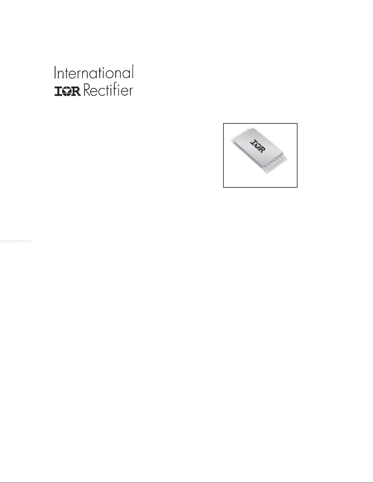
These converters are hermetically packaged in two
enclosure variations, utilizing copper core pins to
minimize resistive DC losses. Three lead styles are
available, each fabricated with International Rectifier’s
rugged ceramic lead-to-package seal assuring long
term hermeticity in the most harsh environments.
PD-94460C
AFL28XXS SERIES
28V Input, Single Output
AFL
Features
n 16V To 40V Input Range
n 5V, 7V, 8V, 9V,12V,15V and 28V Outputs
Available
n High Power Density - up to 84W/in
n Up To 120W Output Power
n Parallel Operation with Power Sharing
n Low Profile (0.380") Seam Welded Package
n Ceramic Feedthru Copper Core Pins
n High Efficiency - to 85%
n Full Military Temperature Range
n Continuous Short Circuit and Overload
Protection
n Primary and Secondary Referenced
Inhibit Functions
n Line Rejection > 40dB - DC to 50KHz
n External Synchronization Port
n Fault Tolerant Design
n Dual Output Versions Available
n Standard Microcircuit Drawings Available
3
Manufactured in a facility fully qualified to MIL-PRF38534, these converters are fabricated utilizing DSCC
qualified processes. For available screening options,
refer to device screening table in the data sheet.
Variations in electrical, mechanical and screening can
be accommodated. Contact IR Santa Clara for special
requirements.
www.irf.com 1
12/18/06
AFL28XXS Series
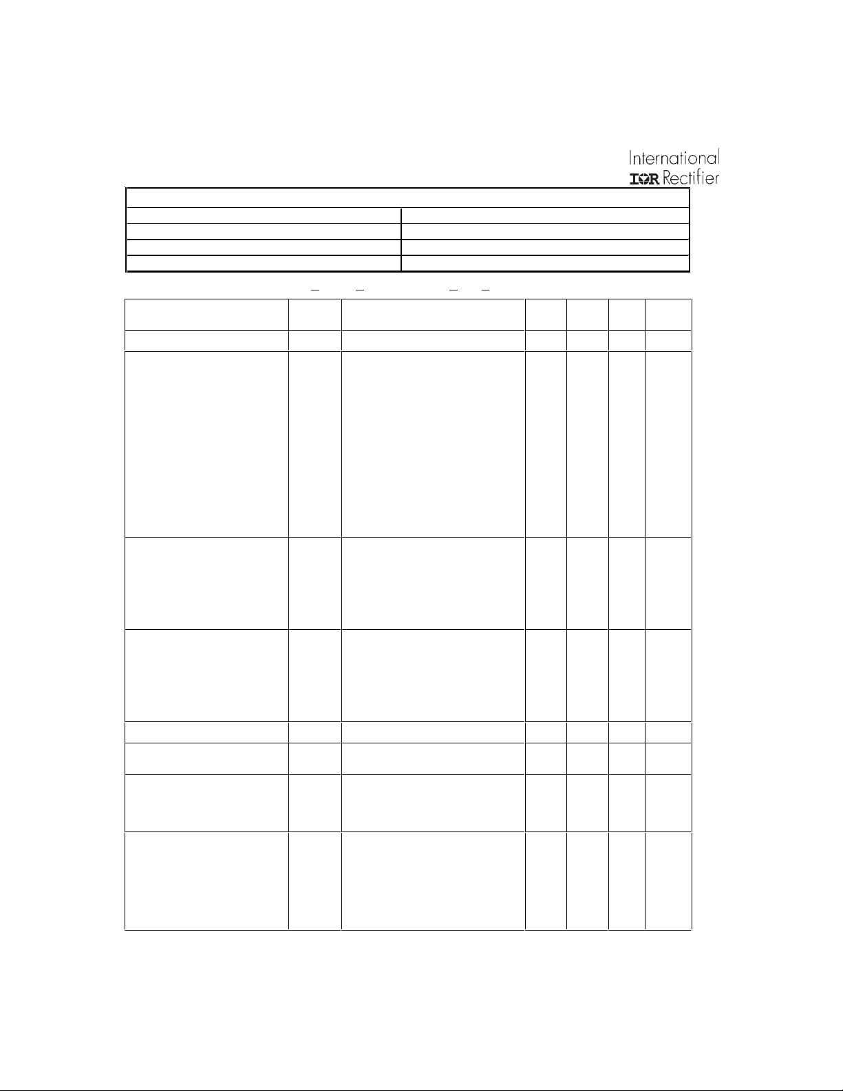
Specifications
Absolute Maximum Ratings
Input voltage -0.5V to +50VDC
Soldering temperature 300°C for 10 seconds
Operating case temperature -55°C to +125°C
Storage case temperature -65°C to +135°C
Static Characteristics -55°C < T
Parameter
INPUT VOLTAGE Note 6 16 28 40 V
OUTPUT VOLTAGE
AFL2805S
AFL2807S
AFL2808S
AFL2809S
AFL2812S
AFL2815S
AFL2828S
AFL2805S
AFL2807S
AFL2808S
AFL2809S
AFL2812S
AFL2815S
AFL2828S
OUTPUT CURRENT
AFL2805S
AFL2807S
AFL2809S
AFL2812S
AFL2815S
AFL2828S
OUTPUT POWER
AFL2805S
AFL2807S
AFL2809S
AFL2812S
AFL2815S
AFL2828S
MAXIMUM CAPACITIVE LOAD Note 1 10,000
OUTPUT VOLTAGE
TEMPERATURE COEFFICIENT
OUTPUT VOLTAGE REGULATION
AFL2828S Line
All Others Line
Load
OUTPUT RIPPLE VOLTAGE
AFL2805S
AFL2807S
AFL2808S
AFL2809S
AFL2812S
AFL2815S
AFL2828S
For Notes to Specifications, refer to page 4
AFL2808S
AFL2808S
Subgroups
Group A
2, 3
2, 3
2, 3
2, 3
2, 3
2, 3
2, 3
1, 2, 3
1, 2, 3
1, 2, 3
1, 2, 3
1, 2, 3
1, 2, 3
1, 2, 3
1, 2, 3
1, 2, 3
1, 2, 3
< +125°C, 16V< VIN < 40V unless otherwise specified.
CASE
Test Conditions
VIN = 28 Volts, 100% Load
1
1
1
1
1
1
1
VIN = 16, 28, 40 Volts - Note 6
Note 6
VIN = 28 Volts, 100% Load - Note 1, 6 -0.015 +0.015 %/°C
No Load, 50% Load, 100% Load
VIN = 16, 28, 40 Volts
VIN = 16, 28, 40 Volts, 100% Load,
BW = 10MHz
Min Nom Max Unit
4.95
6.93
7.92
8.91
11.88
14.85
27.72
4.90
6.86
7.84
8.82
11.76
14.70
27.44
-70
-20
-1.0
5.00
7.00
8.00
9.00
12.00
15.00
28.00
5.05
7.07
8.08
9.09
12.12
15.15
28.28
5.10
7.17
8.16
9.18
12.24
15.30
28.56
16
11.4
10
10
9.0
8.0
4.0
80
80
80
90
108
120
112
+70
+20
+1.0
30
40
40
40
45
50
100
2 www.irf.com
mV
V
A
W
µF
mV
mV
%
pp
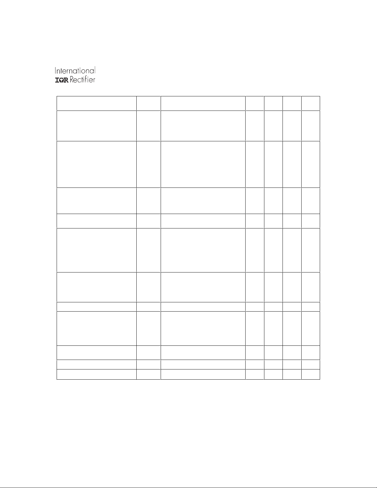
Static Characteristics (Continued)
Parameter
INPUT CURRENT
No Load
Inhibit 1
Inhibit 2
INPUT RIPPLE CURRENT
AFL2805S
AFL2807S
AFL2809S
AFL2812S
AFL2815S
AFL2828S
CURRENT LIMIT POINT
As a percentage of full rated load
LOAD FAULT POWER DISSIPATION
Overload or Short Circuit
EFFICIENCY
AFL2805S
AFL2807S
AFL2809S
AFL2812S
AFL2815S
AFL2828S
ENABLE INPUTS
Sink Current
Converter On
Sink Current
SWITCHING FREQUENCY
SYNCHRONIZATION INPUT
Pulse Amplitude, Hi
Pulse Amplitude, Lo
Pulse Ris e Time
Pulse Duty Cycle
ISOLATION
DEVICE WEIGHT
MTBF
AFL2808S
AFL2808S
(Inhibit Function)
Converter Off
Frequency Range
1 Input to Output or Any Pin to Case
Group A
Subgroups
1
2, 3
1, 2, 3
1, 2, 3
1, 2, 3
1, 2, 3
1, 2, 3
1, 2, 3
1, 2, 3
1, 2, 3
1, 2, 3
1
2
3
1, 2, 3
1, 2, 3
1, 2, 3
1, 2, 3
1, 2, 3
1, 2, 3
1, 2, 3
1, 2, 3
1, 2, 3
1, 2, 3
1, 2, 3 500 550 600 KHz
1, 2, 3
1, 2, 3
1, 2, 3
Slight Variations with Case Style 85 g
MIL-HDBK-217F, AIF @ TC = 70°C 300 KHrs
Test Condit ion s
V
= 28 Volts
IN
I
= 0
OUT
Pin 4 Shorted to Pin 2
Pin 12 Shorted to Pin 8
VIN = 28 Volts, 100% Load, BW = 10MHz
= 90% V
V
OUT
Note 5
= 28 Volts
V
IN
= 28 Volts, 100% Load
V
IN
Logical Low on Pin 4 or Pin 12
Note 1
Logical High on Pin 4 and Pin 12 - Note 9
Note 1
Note 1
Note 1
(except Pin 3). Test @ 500VDC
, VIN = 28 Volts
NOM
AFL28XXS Series
Min Nom Max Unit
115
105
125
78
79
79
80
80
81
81
-0.5
2.0
500
2.0
-0.5
20
100
81
82
82
83
84
85
84
80
100
5.0
50
60
60
60
60
60
60
60
125
115
140
33
0.8
100
50
100
700
10
0.8
100
80
mA
mA
µA
µ
KHz
ns
MΩ
%
W
%
V
V
V
V
%
A
pp
For Notes to Specifications, refer to page 4
www.irf.com 3

AFL28XXS Series
Dynamic Characteristics -55°C < T
Param eter
LOAD TRANSIENT RESPONSE
AFL2805S Amplitude
Recovery
Amplit ude
Recovery
AFL2807S Amplitude
Recovery
Amplit ude
Recovery
AFL2808S Amplitude
Recovery
Amplit ude
Recovery
AFL2809S Amplitude
Recovery
Amplit ude
Recovery
AFL2812S Amplitude
Recovery
Amplit ude
Recovery
AFL2815S Amplitude
Recovery
Amplit ude
Recovery
AFL2828S Amplitude
Recovery
Amplit ude
Recovery
LINE TRANSIENT RESPONSE
Amplit ude
Recovery
TURN-ON CHARACTERISTICS
Overshoot
Delay
LOAD FAULT RECOVERY Same as Turn On Characteristics.
LINE REJECTION
Notes to Specifications:
1. Parameters not 100% tested but are guaranteed to the limits specified in the table.
2. Recovery time is measured from the initiation of the transient to where V
3. Line transient transition time ≥ 100µs.
4. Turn-on delay is measured with an input voltage rise time of between 100V and 500V per millisecond.
5. Current limit point is that condition of excess load causing output voltage to drop to 90% of nominal.
6. Parameter verified as part of another test.
7. All electrical tests are performed with the remote sense leads connected to the output leads at the load.
8. Load transient transition time ≥ 10µs.
9. Enable inputs internally pulled high. Nominal open circuit voltage ≈ 4.0VDC.
Group A
Subgroups
4, 5, 6
4, 5, 6
4, 5, 6
4, 5, 6
4, 5, 6
4, 5, 6
4, 5, 6
4, 5, 6
4, 5, 6
4, 5, 6
4, 5, 6
4, 5, 6
4, 5, 6
4, 5, 6
4, 5, 6
4, 5, 6
4, 5, 6
4, 5, 6
4, 5, 6
4, 5, 6
4, 5, 6
4, 5, 6
4, 5, 6
4, 5, 6
4, 5, 6
4, 5, 6
4, 5, 6
4, 5, 6
4, 5, 6
4, 5, 6
MIL-STD-461D, CS101, 30Hz to 50KHz
< +125°C, VIN=28V unless otherwise specified.
CASE
Test Conditions
Note 2, 8
Load Step 50% ⇔ 100%
Load Step 10% ⇔ 50%
Load Step 50% ⇔ 100%
Load Step 10% ⇔ 50%
Load Step 50% ⇔ 100%
Load Step 10% ⇔ 50%
Load Step 50% ⇔ 100%
Load Step 10% ⇔ 50%
Load Step 50% ⇔ 100%
Load Step 10% ⇔ 50%
Load Step 50% ⇔ 100%
Load Step 10% ⇔ 50%
Load Step 50% ⇔ 100%
Load Step 10% ⇔ 50%
Note 1, 2, 3
VIN Step = 16 ⇔ 40 Volts
VIN = 16, 28, 40 Volts. Note 4
Enabl e 1, 2 on. (Pins 4, 12 high or
open)
Note 1
has returned to within ±1.0% of V
OUT
Min Nom Max Unit
-450
-450
-500
-500
-500
-500
-600
-600
-750
-750
-750
-750
-1200
-1200
-500
0
40 50 dB
4.0
450
200
450
400
500
200
500
400
500
200
500
400
600
200
600
400
750
200
750
400
750
200
750
400
1200
200
1200
400
500
500
250
10
at 50% load.
OUT
mV
µs
mV
µ
mV
µs
mV
µ
mV
µs
mV
µs
mV
µs
mV
µs
mV
µs
mV
µs
mV
µs
mV
µs
mV
µs
mV
µs
mV
µs
mV
ms
s
s
4 www.irf.com
 Loading...