

IR Energy Even-Tube ETO-100 Series Installation, Operation And Service Instructions
Series Even-Tube
Model ETO-100
Infrared Patio Heater
Installation, Operation and Service Instructions
WARNING: FOR OUTDOOR USE ONLY
DANGER
If you smell gas:
1. Shut off gas to appliance.
2. Extinguish any open flame.
3. If odour continues, immediately
call your gas supplier.
FOR YOUR SAFETY
Do not store or use gasoline or other
flammable vapours and liquids in the
vicinity of this or any other appliance.
An LP cylinder not connected for use
shall not be stored in the vicinity of
this or any other appliance.
WARNING:
Improper installation, adjustment, alteration,
service or maintenance can cause injury or
property damage. Read the installation, operating
and maintenance instructions thoroughly before
installing or servicing this equipment.
INSTALLER:
Installer must leave these instructions with the
owner. Only those who are certified to do so
should perform service on these heaters.
OWNER:
Retain these instructions for future reference.
23-428 Millen Road
Stoney Creek, ON. L8E 3N9 Canada
www.irenergy.ca

SERIESEVEN‐TUBE 2 JULY/25/2012

Table Of Contents
CAUTIONANDGENERALSAFETY.............................................................................................................4
S
AFETYREQUIREMENTS.............................................................................................................................................4
GENERAL................................................................................................................................................5
I
NSTALLATIONCODES................................................................................................................................................5
G
ENERALINSTALLATIONANDGASCODES.....................................................................................................................5
ASSUPPLYLINES............................................................................................................................... .....................5
G
LECTRICAL..............................................................................................................................................................5
E
SPECIFICATIONS......................................................................................................................................6
H
EATERCOMPONENTS:.............................................................................................................................................6
D
IMENSIONALDETAILS:............................................................................................................................... ..............8
INSTALLATIONREQUIREMENTS............................................................................................................10
P
OWER&GASSPECIFICATIONS................................................................................................................................10
C
LEARANCETOCOMBUSTIBLES.................................................................................................................................11
EATERMOUNTING...............................................................................................................................................13
H
INSTALLATIONINSTRUCTIONS..............................................................................................................14
NSTALLATIONSEQUENCE:.......................................................................................................................................14
I
ANGERINSTALLATION:..........................................................................................................................................15
H
T
UBEINSTALLATION:...............................................................................................................................................16
EATERINSTALLATION:...........................................................................................................................................18
H
AFFLEINSTALLATION:............................................................................................................................................19
B
F
RESHAIRINLETINSTALLATION:...............................................................................................................................20
IRSTSYSTEMINSTALLATIONCHECK:.........................................................................................................................21
F
R
EFLECTORINSTALLATION:............................................................................................................................... ........22
ECO‐GRILLEINSTALLATION:....................................................................................................................................26
D
V
ENTING...............................................................................................................................................................30
GASCONNECTIONS...............................................................................................................................31
I
NSTALLATION/CODEREQUIREMENTS.......................................................................................................................31
WIRINGDIAGRAMS..............................................................................................................................32
G
ENERALREQUIREMENTS........................................................................................................................................32
LIGHTING&SHUTDOWNINSTRUCTIONS..............................................................................................34
IGHTING..............................................................................................................................................................34
L
HUTDOWN.........................................................................................................................................................34
S
MAINTENANCE&TROUBLESHOOTING................................................................................................35
M
AINTENANCE.......................................................................................................................................................35
ROUBLESHOOTING...............................................................................................................................................35
T
T
ROUBLESHOOTINGCHART......................................................................................................................................37
PARTSLIST............................................................................................................................................38
WARRANTY..........................................................................................................................................39
SERIESEVEN‐TUBE 3 JULY/25/2012

Caution and General Safety
CAUTION: FIRE OR BURN INJURY HAZARD
• At all times maintain clearance to combustible materials as further specified in this manual.
Failure to do so can result in serious fire hazard.
• Never operate heaters in atmosphere containing flammable vapours or combustible dusts.
• This heater is equipped with an electronic and automatic ignition device. Do not attempt to
light the burner by hand. Failure to comply can result in a serious fire and personal injury
hazard.
• Certain materials, when stored under this heater are subjected to radiant heat can soften,
distort or otherwise be damaged, special care should be taken of plastic materials
• Appliance surfaces, other than the obvious flame and emitter surfaces, attain elevated
temperatures during operation. Do not touch the heater head during operation. Everyone
should be alerted to this hazard to avoid burning.
• Children should be strictly supervised when in the area of this heating appliance. Playing or
running around the structure should be strictly forbidden.
• Clothing or other flammable materials should not be hung on or near this heater.
• Any guard or other protective device removed for servicing the heater must be replaced
prior to operating the heater.
• Installation and repair should be done by a qualified service person. The heater should be
inspected before use and at least annually by a qualified service person.
Safety Requirements
1. Never locate the heater directly below electrical lines, gas lines or sprinkler systems.
2. Do not locate heater too close to vinyl or plastic wall coverings. These materials may
discolour or soften well before they reach combustible limits.
3. The heater requires a minimum clearance from combustible materials. See the
Clearance to Combustible Materials section for specific requirements.
4. Always allow room for maintenance purposes.
5. The heater aspirates air for combustion. Do not locate heater where there are severe
draft conditions or airflow restrictions to the burner.
SERIESEVEN‐TUBE 4 JULY/25/2012

General
Installation Codes
Installations must comply with local building codes, or in their absence, the latest edition of the
national regulations and procedures as listed below.
General Installation and Gas Codes
Heaters must be installed only for use with the type of gas appearing on the rating plate, and the
installation must conform to the National Fuel Gas Code, ANSI Z223.1/NFPA 54 in the US and
CAN/CGA B149.1 and B149.2 Installation Codes in Canada.
This heater maybe approved for either indoor or outdoor installation. Not for use in residential
dwellings, refer to Rating plate.
Gas Supply Lines
Gas supply pipe sizing must be in accordance with the National Fuel Gas Code, ANSI
Z223.1/NFPA 54 in the US and CAN/CGA B149.1 and B149.2 Installation Codes in Canada.
A 1/8" NPT plugged tap must be installed in the gas line connection immediately upstream of the
burner farthest from the gas supply meter to allow checking of system gas pressure.
Electrical
All heaters must be electrically grounded in accordance with the National Electric Code,
ANSI/NFPA 70 in the US, and the Canadian Electric Code, CSA C22.1 in Canada, and must
comply with all local requirements.
SERIESEVEN‐TUBE 5 JULY/25/2012

Specifications
Heater Components:
#8-32 x 1-1/4"
Hanger
QTY (3)
Heater
5/16 Nut
QTY (5)
5/16 J-Bolt
QTY (1)
Reflector
Bracket
QTY (1)
Screws
QTY (6)
5/16 Lock
Washer
QTY (4)
Spring Clip
QTY (1)
Coupling
QTY (1)
Front
End Cap
QTY (1)
Gasket
QTY (1)
End Cap
Extension
QTY (1)
S/S Band
Exhaust Screen
QTY (1)
Clamp
QTY (1)
Cross Strap
QTY (2)
Exhaust
End Cap
QTY (1)
Fresh
Air
Inlet
QTY (1)
SERIESEVEN‐TUBE 6 JULY/25/2012
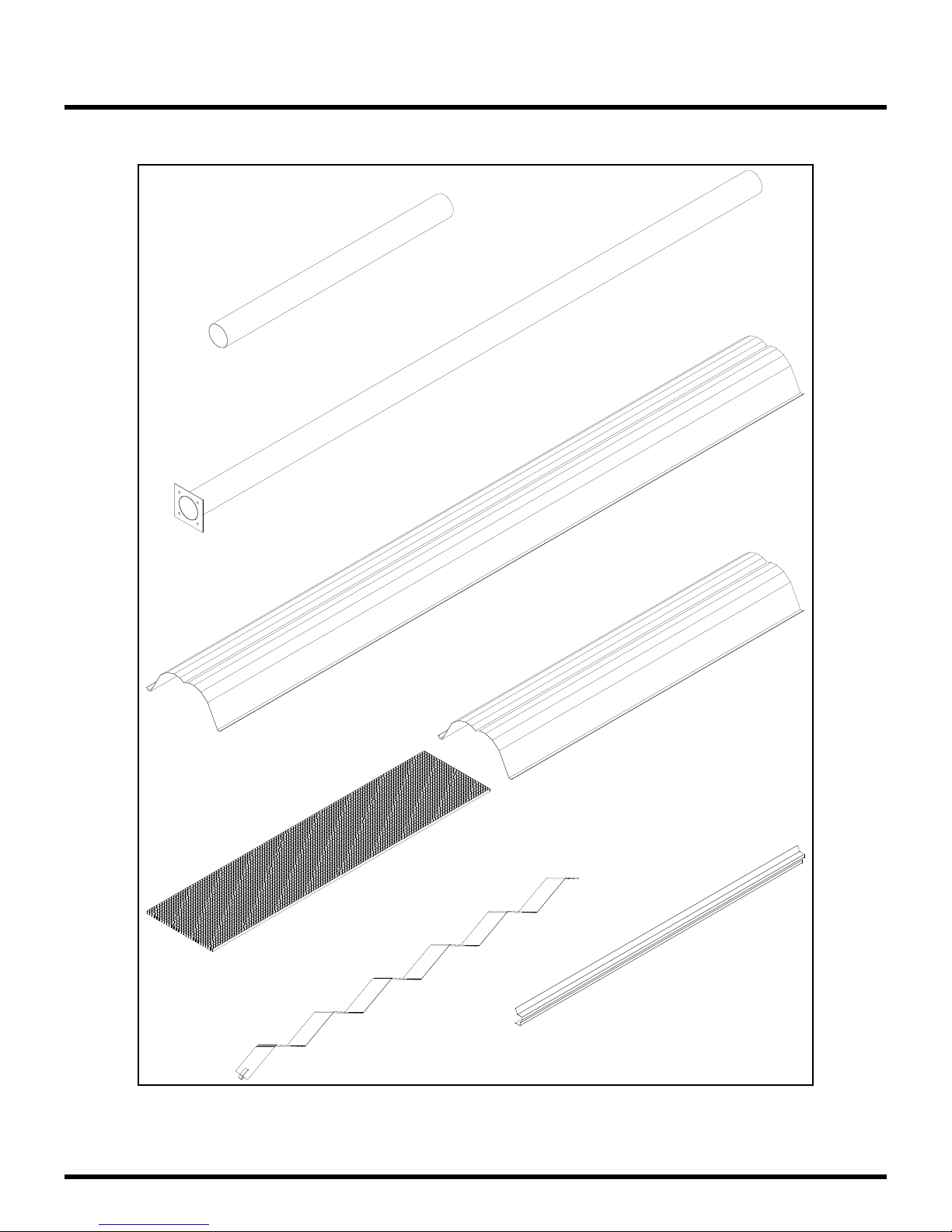
Heater Components continued:
4' Extension
Tube
QTY (1)
Specifications
10' Tube
QTY (1)
Deco-Grille
QTY (3)
Baffle
QTY (1)
10' Reflector
QTY (1)
5' Reflector
QTY (1)
Deco Grille Side Support
QTY (6)
SERIESEVEN‐TUBE 7 JULY/25/2012
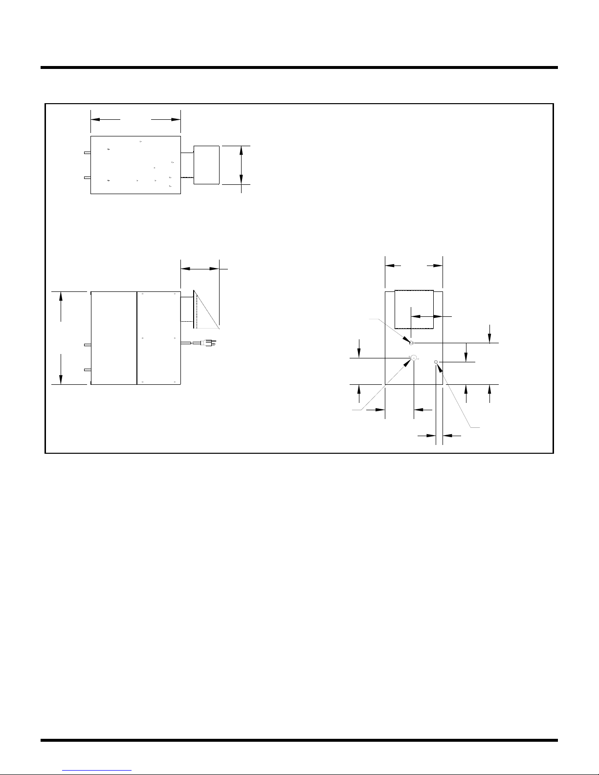
Specifications
Dimensional Details:
14.1
6.0
5.9
Electrical
Cord Location
14.5
Location
Note: All dimensions are in inches.
Gas
inlet
4.2
4.5
1.1
9.0
4.9
6.5
3.5
Thermostat
Connection
SERIESEVEN‐TUBE 8 JULY/25/2012

Dimensional Details continued:
Specifications
14.5
16.7
9.0
6.0
3.8108.048.0
14.0
194.9
Note: All dimensions are in inches.
SERIESEVEN‐TUBE 9 JULY/25/2012
180.0

Installation Requirements
Power & Gas Specifications
Gas Supply
Rated Input Hi Fire Low Fire
100,000 BTU 75,000 BTU
Inlet Pressure
Min. 5.0” W.C. 11.5” W.C.
Max. 14.0” W.C. 14.0” W.C.
Manifold Pressure Natural Gas: Propane Gas:
High Rate 3.3” W.C. 10.2” W.C.
Low Rate 2.0” W.C. 6.4” W.C.
Inlet Connection Natural Gas: Propane Gas:
Natural Gas: Propane Gas:
½” Female NPT ½” Female NPT
Electrical Supply
120 VAC, 60Hz. 1Amp: 36” Cord with grounded 3 prong plug.
Important
Installation or repair should only be done by a qualified service person. The heater should
be inspected before use and at least annually by a qualified service person.
The appliance and its individual shutoff valve must be disconnected from the gas supply
piping system during any pressure testing of that system at test pressures in excess of ½
psig (3.5 kPa)
The appliance must be isolated from the gas supply piping system by closing its individual
manual shutoff valve during any pressure testing of the gas supply piping system at test
pressures equal to or less than ½ psig (3.5 kPa)
SERIESEVEN‐TUBE 10 JULY/25/2012

Installation Requirements
Clearance to Combustibles
A general clearance of 18” (0.5 m) in every direction is recommended for servicing only around
each Burner, also to ensure adequate air flow in and around the Heating System.
In addition to this it is very important to observe the minimum clearance to combustibles at
all times to avoid any possibility of property damage or personal injury.
Table below lists the minimum clearance to combustible materials for various installation
configurations. Additional clearance may be required for glass, painted surfaces and other
materials which maybe damaged by radiant or convective heat.
Combustible materials are considered to be wood, compressed paper, plant fibres, plastics,
Plexiglas or other materials capable of being ignited and burned. Such materials shall be
considered combustible even though flame-proofed, fire-retardant treated or plastered.
Adequate clearance to sprinkler heads must be maintained.
The stated clearance to combustibles represents a surface temperature of 90°F (50°C) above
room temperature. Building materials with low heat tolerance (such as plastics, vinyl siding,
canvas, tri-ply, etc…) maybe subject to degradation at lower temperatures. It is the installer’s
responsibility to assure that adjacent materials are protected from degradation.
Note with an ambient temperature of 70°F the surface temperatures at the clearance
distances listed below could reach 160°F, Care should be taken with placement of plastic or
vinyl in the proximity of the heater as they tend to distort and soften at these temperatures.
NOTE: Sprinkler head heat fuse link performance may alter with age.
SERIESEVEN‐TUBE 11 JULY/25/2012

Installation Requirements
Reflector Configurations Dim ETO-100
Horizontal
Model No.:
A
B
C
45° Reflector Tilt
A
B
C
Ends (both sides)
This heater can be installed between wood beams with minimum distances as shown. Air flow
MUST NOT be restricted.
D
D
A
B
C
D
A
B
C
D
4”
4"
29"
73.5"
29"
8"
2.5"
55.5"
43"
Trusses CAN'T be enclosed
NOTE: Some materials deteriorate or soften at sustained temperatures below 160°F.
Consult material manufacturer for recommendations
SERIESEVEN‐TUBE 12 JULY/25/2012
Wood Beam
1/2"
 Loading...