

Irbit Motorcycle Factory Gear Up (2004), Patrol (2004), Tourist (2004), Troyka (2004) Owner's Manual
Irbit Motorcycle Factory
Irbit Motorworks of America
Owners Manual
2004 Model
Gear Up, Patrol, Tourist, Troyka
www .imz-ural.com

2

Contents
Introduction...............................................................................................................................................................7
W arnings, Cautions, Notes.........................................................................................................................................9
Chapter 1 Specifications
Specifications .........................................................................................................................................................11
T orque Specifications............................................................................................................................................. 15
Chapter 2 Motorcycle Controls and Instruments
Motorcycle Controls & Instrumentation.................................................................................................................. 17
Controls ................................................................................................................................................................ 17
Control and Instrument maintenance ....................................................................................................................... 25
Chapter 3 Engine Operation
Engine Operation and Maintenance ........................................................................................................................ 27
Pre-Trip Preliminaries ............................................................................................................................................ 27
Starting the Engine ................................................................................................................................................. 27
Operating Precautions............................................................................................................................................ 31
Running-In the New Motorcycle ............................................................................................................................ 32
Chapter 4 Engine Design
Brief Description of Design .................................................................................................................................. 33
Lubrication System ................................................................................................................................................ 34
Fuel System........................................................................................................................................................... 35
Ignition System ...................................................................................................................................................... 37
Chapter 5 Carburetors
Carburetors ........................................................................................................................................................... 39
Carburetor Maintenance ........................................................................................................................................ 40
Chapter 6 Power T ransmission
Power Transmission............................................................................................................................................... 41
Clutch ................................................................................................................................................................... 41
Gearbox ................................................................................................................................................................ 41
Final Drive............................................................................................................................................................. 42
3

Chapter 7 Running Gear
Running Gear......................................................................................................................................................... 43
Motorcycle and Sidecar Frames ............................................................................................................................ 43
Spring-Loaded Hydraulic Shock Absorber............................................................................................................. 44
Adjustment of Sidecar Installation ........................................................................................................................ ..45
Front Fork ............................................................................................................................................................ 46
Steering Head Bearings............................................................................................................................................48
Chapter 8 Wheel & Tires
Wheels and Tires ................................................................................................................................................... 49
Tire Data ................................................................................................................................................................50
Running Gear Maintenance .................................................................................................................................... 51
Chapter 9 Brakes
Brakes .................................................................................................................................................................. 53
Brake Adjustment .................................................................................................................................................. 53
Chapter 1 1 Electrical
Electrical Equipment .............................................................................................................................................. 57
Electrical Circuits.....................................................................................................................................................59
Electrical Equipment Maintenance .......................................................................................................................... 59
Wiring Diagram...................................................................................................................................................... 60
Chapter 12 Maintenance
Maintenance of Motorcycle ................................................................................................................................... 61
List of Recommended Lubricants ........................................................................................................................... 61
Lubrication Chart................................................................................................................................................... 63
Required Lubrication ............................................................................................................................................. 64
Care of Motorcycle Paint....................................................................................................................................... 64
Preservation and Storage ....................................................................................................................................... 65
Battery .................................................................................................................................................................. 65
List of Individual T ool Set, Spare Parts, Accessories & Documents......................................................................... 66
Chapter 13 Gear-Up & Patrol Motorcycle With Engageable Sidecar Drive
Patrol Motorcycle with Engageable Sidecar Drive ................................................................................................. 69
Description ............................................................................................................................................................ 69
Handling Differences from the Single Wheel Drive .................................................................................................. 69
Sidecar Maintenance ............................................................................................................................................. 70
Chapter 14 Learning to Ride the URAL
Learning to Ride the Ural Motorcycle with Sidecar Accessory ................................................................................ 71
Safe Operating Rules ............................................................................................................................................. 73
4

Chapter 15 Warranty
Warranty............................................................................................................................................................... 75
W arranty Claim Form........................................................................................................................................... 81
Flat Rate Schedule ............................................................................................................................................... 82
Chapter 16 Service Coupons
Service Coupons ................................................................................................................................................... 85
New Address Form ............................................................................................................................................... 95
New Owner Form ................................................................................................................................................. 96
URAL S tarting and Running Tips ............................................................................................................................ 97
5

6

INTRODUCTION
Welcome to the URAL Motorcycling Family! Y our Ural has been built by the Irbit Motorcycle Factory in
Russia and distributed by Irbit Motorworks of America, the United S tates affiliate of the Irbit Motorcycle
Factory . The Ural motorcycle conforms to all applicable US Federal Motor V ehicle Safety Standards and
US Environmental Protection Agency regulations effective on the date of manufacture. This manual
covers the Gear-Up, Patrol, and T ourist models.
This manual has been prepared to acquaint you with the operation, care and maintenance of your
motorcycle, and to provide you with important safety information. Follow these instructions carefully for
maximum motorcycle performance and for your personal motorcycling safety and pleasure. Please pay
particular attention to the section “Learning to Ride the Ural Motorcycle with Sidecar”. It is critical that a
beginning sidecar driver becomes thoroughly familiar with the special operating characteristics of
sidecar outfits before venturing out on the busy roads.
Y our Owner’s Manual contains instructions for operation, maintenance and minor repairs. Major repairs
require the attention of a skilled mechanic and the use of special tools and equipment. Y our Authorized
IMWA Ural Dealer has the facilities, experience and genuine Ural parts necessary to properly render this
valuable service.
Any suggestions or comments are welcome! Write to us or post an e-mail on the Ural Discussion
bulletin board at www.imz-ural.com.
Happy Riding!
7

8

Important Notice!
St atements in this manual preceded by the following words are of special importance:
WARNING: MEANS THERE IS THE POSSIBILITY OF PERSONAL INJURY TO
YOURSELF
OR OTHERS.
CAUTION: Means there is the possibility of damage to the vehicle.
NOTE: Other information of particular importance has been placed in
italic type.
CAUTION! During the initial 1,500 km, a fundamental bedding-in of parts for all the
mechanisms of the motorcycle takes place. During this period do not race, overload, or lug the
engine.
Note the riding procedures described in the section “Running-In of New Motorcycle.”
Following those procedures will ensure that you have the most powerful & smoothly operating
engine after break-in.
Maintenance intervals recommended are based on operational experience under various climatic and
road conditions. However, these intervals may be modified following repeated checks of the lubricant
condition and general mechanical condition of the motorcycle.
Carefully study this Owner’s Manual before starting the motorcycle.
Specifications and design are subject to change without notice.
9

10

Chapter 1
SPECIFICATIONS
GENERAL
Patrol & Gear-Up Tourist
Maximum speed of motorcycle 95 km/h 59 mph 105 km/h 65 mph
Dry mass of motorcycle 736 lb 736 lb.
Maximum Gross Vehicle W eight 1344lb. 1344 lb.
Noise level below 80db below 80db
Fuel consumption 31.3 mpg 31.3mpg
OVERALL DIMENSIONS
Length 2580 mm / 8 ft
Width 1700 mm / 5 ft 6 in
Height 1 100 mm / 3 ft 6 in
Road Clearance 125 mm / 5 in
Seat height 840 mm / 33 in
Wheel base 1470 mm / 58 in
ENGINE
Type 4 stroke, overhead valves, opposed twin-cylinder
Displacement 745 cc
Cylinder bore 78 mm
Piston stroke 78 mm
Compression ratio 8.6 :1
Rated horsepower 23 KW / 45 BHp
Rated rotational speed 5600 RPM
Rated torque 52 N -M @ 3750 RPM
Lubrication system Dual system of forced lubrication and splashing
Lubricant SAE 20W/50
CARBURETOR
Carburetor type 32 CVK Keihin
Number of carburetors 2
Air cleaner Paper Filter Element
Fuel 91 octane premium unleaded gasoline
PCV V alve Internal Breather
11

ELECTRICAL
Ignition system Electronic Ignition
Sp ark plugs NGK BP7HS or Equivalent
Ignition timing Automatic advance
Alternator 35 amp / 12 V olt
Battery V ART A YB18L-A or equivalent
Headlight Hela, 7" round sealed beam
TRANSMISSION
Clutch Dry double-disk clutch
Gearbox 4 speed gearbox with reverse
GEAR RA TIOS
I gear 3.6
II gear 2.28
III gear 1.56
IV gear 1.19
Reverse gear 4.36
Speedometer drive ratio 0.4
Final drive ratio 4.62
FLUID CAP ACITIES
Patrol, Gear Up T ourist
Fuel tank (gasoline) 5 Gal / 19L 5 Gal / 19L
Reserve (gasoline) .5 Gal / 2L .5 Gal / 2L
Engine (oil) 68 Oz / 2L 68 Oz / 2L
Transmission (oil) 34 Oz / 1 L 34 Oz / 1 L
Final drive (gear oil) 4.5 Oz / 105 ml 3.5 Oz / 135 ml
Shock Absorbers (shock oil) 105 ml / 3.5 oz 105 ml / 3.5 oz
Brake Reservoir DOT 3 or 4 brake fluid to upper line
12

RUNNING GEAR
Frame Tubular welded
Rear wheel suspension Swing arms with
spring shock absorbers
Front fork Leading link
Sidecar Cushioned body (on rubber
cushions) and wheel with
hydraulic spring shock absorber
Sidecar drive Steel shaf t driven by final drive. User selectable for engage
(Patrol and Gear Up only) ment.
Brakes Disc-type with hydraulic drive on front, Shoe type with
mechanical drive on rear and sidecar wheels
Tires 4” x 19”
Front 22 psi cold (1.5 Bar / 150 kPa) Front 22 psi cold
Side 22 psi cold (1.5 Bar / 150 kPa) Side 22 psi cold
Rear 36 psi cold (2.5 Bar / 250 kPa) Rear 36 psi cold
CLEARANCES
mm in
V alves with engine cold 0.05 to 0.1 0.002 to 0.004
Between spark plug electrodes 1.016 0.040
Backlash between tooth faces of
bevel gears in final drive 0.1 - 0.3 0.004
FREE TRA VEL / ADJUSTMENTS
mm in
Hand brake control lever 5 - 8 0.2 - 0.3
Clutch control lever 5 - 8 0.2 - 0.3
Foot brake drive pedal ¼ of full stroke of pedal,
25 - 30 1.0 - 1.2
Toe-in distance 10 m m 3/8 inch
Lean-out 1° away from sidecar
13

This page left intentionally blank
14

TORQUE SPECIFICA TIONS
Metric US Equivalent Location on Bike
54 to 61 Nm 40 ft/lb to 45 ft/lb cylinder heads
237 to 251 Nm 175 ft/lb to 185 ft/lb fly wheel tightening screws
19 to 30 Nm top 14 ft/lb to 22 ft/lb shock absorber
38 to 49 Nm bottom 28 ft/lb to 36 ft/lb shock absorber
30 to 35 Nm 22 ft/lb to 26 ft/lb bearing nut
30 to 35 Nm 22 ft/lb to 26 ft/lb final drive to swing arm bolts
16 to 19 Nm 12 ft/lb to 14 ft/lb oil pump bolt
6.7 to 11 Nm 5 ft/lb to 8 ft/lb engine sump
14 to 19 Nm 10 ft/lb to 14 ft/lb final drive case nuts
25 to 30 Nm 18 ft/lb to 22 ft/lb nut fastening the pinion bearing
(Patrol, Gear Up rear axle only)
68 to 90 Nm 50 ft/lb to 66 ft/lb nut fastening the pinion bearing
22 to 27 Nm 16 ft/lb to 20 ft/lb reverse gear lever nut
19 to 22 Nm 14 ft/lb to 16 ft/lb alternator gear nut
136 to 163 Nm 100 ft/lb to 120 ft/lb steering stem nut
15

This page left intentionally blank
16

Chapter 2
MOTORCYCLE CONTROLS & INSTRUMENTATION
Figure 1. Controls and Instrumentation
1 - Speedometer 12 - Gear shift (foot) pedal
2 - Turn indicator lamp 13 - Turn signal switch
3 - Trip odometer reset knob 14 - Horn push-button
4 - Neutral and reverse gear engagement 15 - “High-low” beam switch
indicator lamp 16 - Clutch control lever
5 - Front brake control lever 17 - Steering damper tightening bolt
6 - Throttle control twist grip 18 - High-beam indicator lamp
7 - Ignition cutoff switch 19 - Ignition Switch
8 - Electric Start Button 20 - Battery discharge warning lamp
9 - Rear brake pedal & sidecar wheel brake 21 - Parking brake
10 - Reverse gear lever
11 - Kick start lever
17
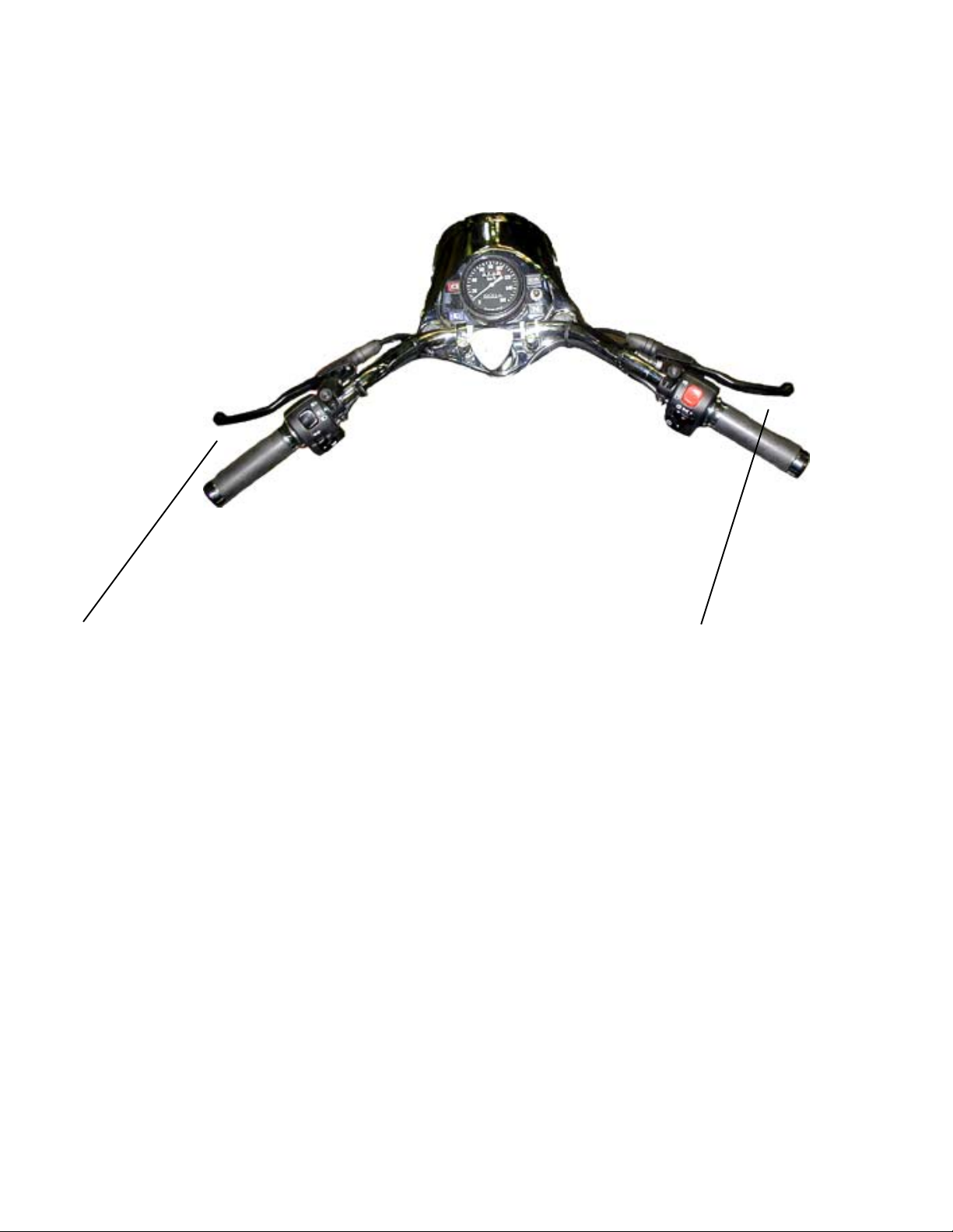
Clutch Control Lever Font Brake Control Lever
Clutch control lever . When the clutch lever is squeezed, the engine is disengaged from the
gearbox. When the lever is released, the engine and gearbox are engaged.
W ARNING: MAKE SURE FINGERS ARE NOT POSITIONED BETWEEN HAND CONTROL LEVERS AND HANDLEBAR
GRIPS
OR OPERATION OF VEHICLE COULD BE IMP AIRED.
W ARNING: BEFORE STARTING ENGINE, ALWAYS SHIFT TRANSMISSION TO NEUTRAL TO PREVENT ACCIDENTAL
MOVEMENT
WHICH COULD CAUSE POSSIBLE DAMAGE TO MOTORCYCLE AND PERSONAL INJURY.
Caution: Always engage the clutch release lever when shifting. Serious internal damage may
result to the transmission if the clutch release lever is not engaged.
Front brake control lever When the lever is squeezed, the front wheel brake is actuated. The
front brake should be used together with rear brake.
When the brake lever is squeezed, the stop signal lights are switched on.
18

Gear Shift Foot Pedal Kick Lever
Kick lever Is designed to start the engine. On pressing the lever the crankshaft of the engine is
actuated through the gearbox. The lever is returned to its initial position by the spring inside the
gearbox.
Gear shift foot pedal Is a two-arm type. When the front arm is depressed, shifting from higher to
lower gear takes place. When the rear arm is depressed, shifting from lower to higher gear takes
place. Since the heel-toe shift lever is short-coupled, you will find it easier to shift into a higher
gear if you do not use your heel to shift, rather the ball of your foot. The neutral position is fixed
between the 1st and 2nd gears. It is important to shift smoothly with a constant force and not to kick
the gear shift pedal. Serious damage may result to the shifting mechanism if the gear shift pedal is
kicked, rather than pushed.
IMPORT ANT! The green pilot lamp will illuminate when either the transmission is in neutral
or when the reverse gear is engaged (see “Starting the Engine”).
19
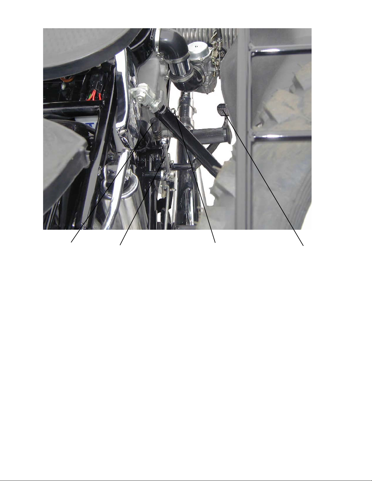
Parking Brake Sidecar Drive Lever Reverse Gear Lever Rear Brake Pedal
Parking Brake is used to hold the bike when parked. To engage, depress the rear brake pedal
and push down then twist the parking brake lever counter clockwise.
Sidecar drive engagement lever is used to engage the drive axle to the sidecar wheel on the
Patrol and Gear Up model motorcycles.
WARNING: Never engage sidecar drive on concrete or hard surface. Severe damage to
drivetrain will result if the sidecar drive is engaged on pavement.
Reverse gear lever is used to move the motorcycle in reverse. The transmission must be in
neutral or 1st gear for reverse gear to be engaged.
Rear brake lever is used to actuate the rear brakes.
W ARNING: D
CAUSE
FRONT
POSSIBLE LOSS OF CONTROL OF THE MOTORCYCLE. ALWA YS USE BOTH BRAKES. NEVER STOP WITH
OR REAR BRAKE ONLY.
O NOT APPLY EITHER BRAKE STRONGLY ENOUGH TO LOCK THE WHEELS BECAUSE THIS MAY
W ARNING: AN IMPROPERLY ADJUSTED REAR BRAKE PEDAL COULD INTERFERE WITH PROPER REAR BRAKE
OPERATION
RESULTING IN POOR BRAKE ACTION.
20

Ignition Switch has three fixed positions of the
key . The position and switching diagram of the
ignition locks are shown above.
Off All electrical systems are off.
R un Voltage is supplied to all electrical systems.
Parking Voltage is supplied to running lights only .
Note: Leaving the key in the Run or Parking position will discharge the battery .
Always return the key to the Off position before removing it.
21
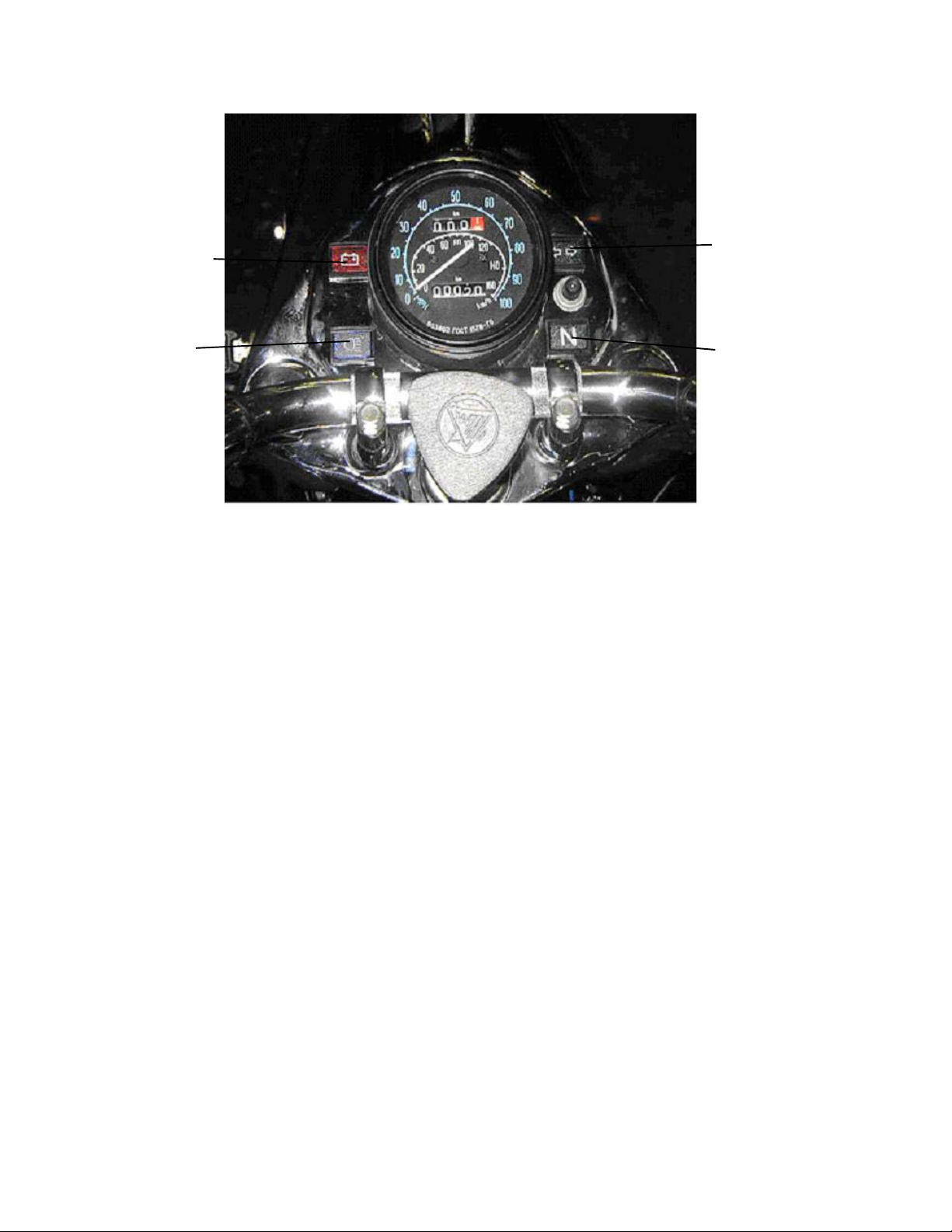
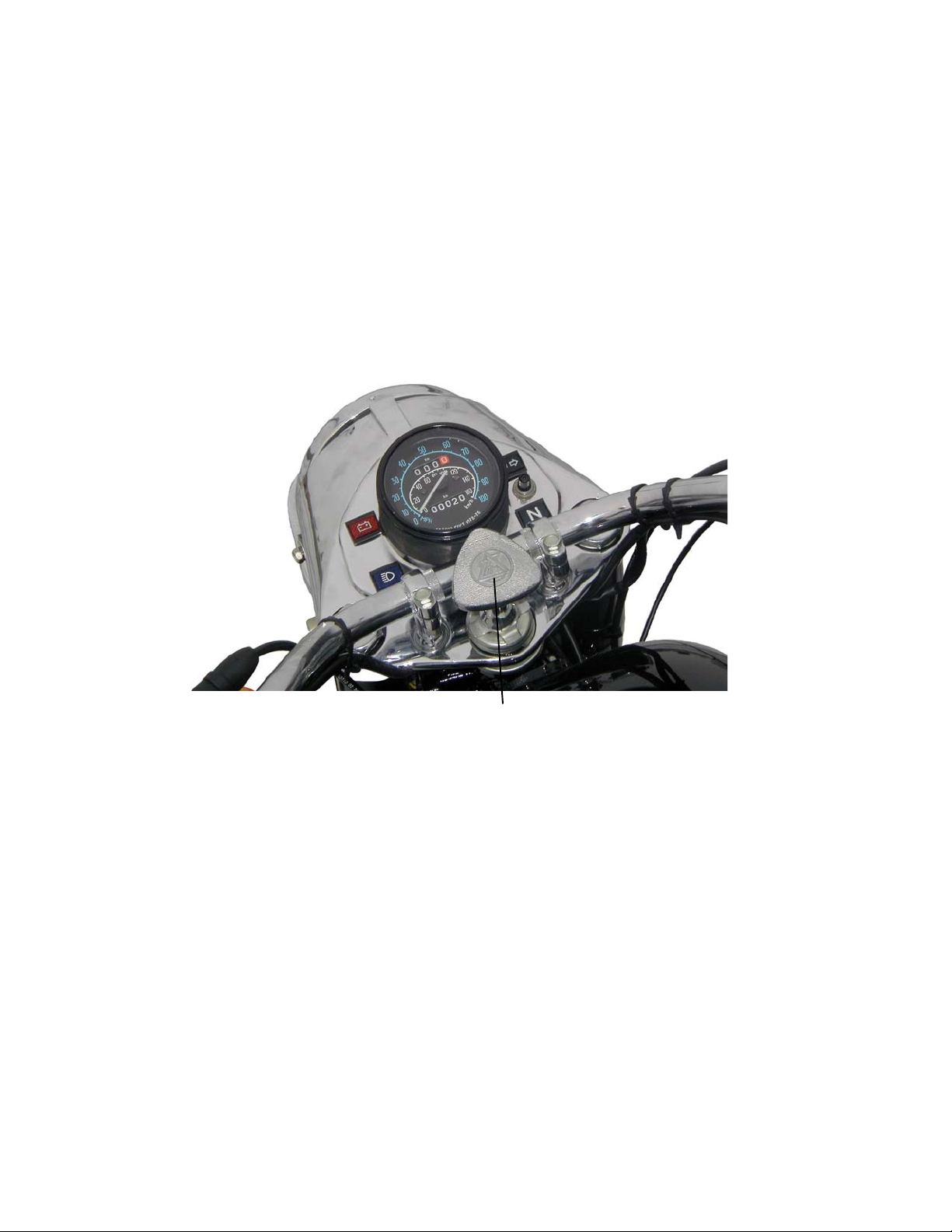
The indicator lamps are mounted on the instrument board:
Alternator failure Turn indicator
indicator lamp pilot lamp
Head lamp high Gearbox neutral
beam indicator indicator lamp
lamp
T urn indicator pilot lamp indicates that the turn signals are activated.
Alternator fault indicator lamp, indicates that the charging system is malfunctioning and needs
immediate attention.
Gearbox neutral and reverse gear engagement, indicates that the gearbox is either in neutral
or in reverse.
Head lamp high beam indicator, indicates that the headlight high beam is activated.
Speedometer is on the dash board, with trip and total odometer . The trip odometer is reset to
zero by rotating knob (Fig.1, # 3) counterclockwise.
Note that the odometer reads in kilometers
not miles.
22
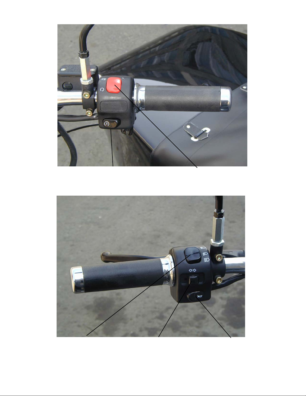
Electric St art Button Ignition Cutoff Switch
Low and High Beam Light Switch T urn Indicator Switch Horn Push Button
23
Throttle Control is on the right handlebar . Turning the twist grip increases engine speed.
Ignition Cutoff Switch has two positions, ignition off (up), and ignition on (down).
Electric Start Button is located on the right-hand twist grip, below the kill switch.
Low and High Beam Light Switch has two positions, high beam (up), and low beam (down).
T urn indicator switch is used for signaling a turn
Horn push-button is used to activate the horn
Steering Damper absorbs lateral kicks to the front wheel. T urning tightening bolt (clockwise in-
creases friction. This can be used while riding over bad roads.
STEERING DAMPER ADJUSTMENT KNOB
W ARNING: DO NOT TIGHTEN THE DAMPER TO THE POINT WHERE THE STEERING BECOMES STIFF. DOING SO
WILL
ADVERSELY AFFECT HANDLING QUALITIES AND MAY DAMAGE THE STEERING MECHANISM.
Parking brake is located on the right side of the motorcycle next to the foot peg. It is engaged by
applying the foot brake pedal fully and turning the handle and pushing it down to hold the foot brake
lever in the applied position.
Always disengage the parking brake before moving the motorcycle.
24

CONTROL CABLE ADJUSTMENT
The control cables are adjusted by screw adjustments at the cable ends.
With the control levers released:
• for the clutch a play at the clutch lever end should be equal to 5 - 8 mm/0.2 - 0.3 in.
• The rear brake pedal equal to about 25 - 30 mm/1- 1.2 in. of the full stroke of the pedal is required
• for the carburetors - carburetor throttle cables synchronized
With the control levers (handles) fully depressed:
• for the clutch — complete disengagement of the engine from the transmission; noiseless shifting
of gears means correct adjustment of the clutch cable.
• for the carburetors — lift of throttles to maximum and equal height
CONTROL CABLE MAINTENANCE
The daily preventative maintenance involves checking the functioning, condition and fastening of
the tie rods, cables and braking action. Refer to the Service Coupons for lubrication schedule.
As per the service coupons;
• check the condition of the brakes
• clean the brake shoes and the active surface of the brake drums
• lubricate the hinge pins and the cams of the brake linings, the joints, the linkage of the rear and
sidecar wheel brakes, the lever axle, the parking brake, the throttle control twist grip, the lever
pins and ends of cables used in the clutch, the front brake control, the control cables used in
the clutch, the front brake and the throttles.
25
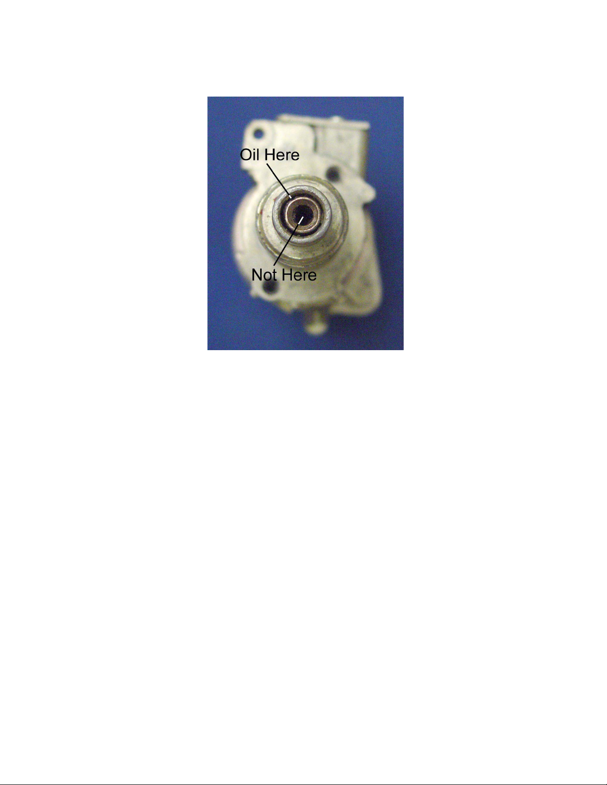
SPEEDOMETER MAINTENANCE
After every 10,000 km, remove the speedometer from the motorcycle and add five or six drops of
oil into the speedometer where the cable inserts into the speedometer . This will lubricate the speedometer internally .
T o lubricate the speedometer cable, remove the cable from the speedometer and extend it in a
straight line. Apply speedometer lubricating oil or light machine oil at one end and allow it to seep
through the length of the cable.
26

Chapter 3
ENGINE OPERATION
PRE-TRIP PRELIMINARIES
Pre-Trip Check List
1. Check all lights and the horn for proper operation.
2. Check the brake and clutch levers and/or pedals.
3. Make sure all wheels and the final drive assemblies are securely fastened .
4. Check the carburetor flanges and air filter ducts for integrity and proper alignment.
5. Check the tire tread depth - should be greater than 1/8 inch.
6. Check the sidecar attachment mounts – all mounts should be securely tightened.
Gasoline level in the fully filled tank should be 10 - 15 mm / ½ - ¾ in. below the lower edge of the
tank filler . Do not overfill the tank.
See that the oil level in the engine crankcase is not higher than the top and not lower than the
bottom marks on the dipstick with the filler plug undone.(See chapter 4 Lubrication System)
CAUTION: When checking the engine oil level, be careful that dirt and debris do not
contaminate the oil.
ST ARTING THE ENGINE
W ARNING: BEFORE STARTING THE ENGINE, MAKE SURE THAT THE GEAR SHIFT MECHANISM IS IN THE
NEUTRAL
CAUSE
IDLING, IT IS ADVISABLE TO USE NEUTRAL GEAR.)
When the ignition is switched on, the green & red lamps on the instrument board should illuminate. Make sure that the reverse gear engagement (lever) is set to the front position. This is
important since the green lamp will also be illuminated if the motorcycle is in reverse gear .
Moving the reverse gear lever forward will put the gearbox in neutral.
POSITION (BETWEEN 1ST AND 2ND GEARS) TO PREVENT ACCIDENT AL MOVEMENT WHICH COULD
POSSIBLE DAMAGE TO MOTORCYCLE AND PERSONAL INJURY. ( FOR MORE THAN JUST STARTING, I.E.
27
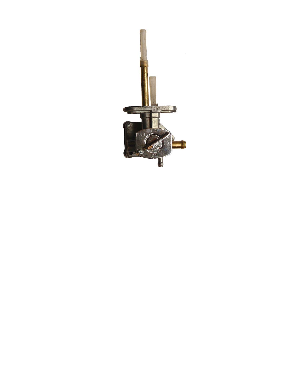
AUTOMATIC PETCOCK
1. When starting the engine after the motorcycle has been parked for an extended period of
time, or after the fuel tank and/or carburetors have been completely emptied of gasoline (e.g.
due to running out of fuel, evaporation, or installation of replacement parts), set the valve to
the “PRI” position. This will allow gasoline to fill the float chambers of the carburetors and
prepare the engine for starting.
2. Start the engine
3. After the engine starts, set the valve to the “ON” position and keep the valve in this position
for regular use of the motorcycle. (When set to “ON”, the valve is automatically activated
when the engine starts and stops, opening and shutting off the supply of fuel to the
carburetors)
4. After using up the main volume of fuel (engines starts stalling due to lack of fuel), set the
valve to the “RES” position and continue driving. After refueling, remember to set the valve
back to “ON” to avoid running out of fuel completely .
IMPORT ANT : When parking the motorcycle for extended periods of time, the valve should
remain in the “ON” position.
WARNING: Never leave the motorcycle with the engine turned off and the valve set to “PRI”
as this may result in a serious damage to the engine and will void your warranty .
28

Enrichener off Enrichener on
The carburetor enricheners provide extra fuel to the mixture. This extra fuel will allow a cold
engine to start and run until it has warmed up sufficiently to allow normal operation. Use caution
when using the enricheners, as they can easily cause the engine to flood, or foul the spark plugs.
The enricheners should only be left on as long as necessary to keep the engine running while
cold and should be turned off as soon as possible.
29

Depending on the engine and ambient temperature, use the carburetor enricheners and starting
procedure as follows:
Manual St arting (without electric starter)
1. T urn on the ignition and depress the kick lever (see Fig. 1) about
1/4 of its travel (enough to firmly get the ball of your foot on the lever) with either your left
foot or right foot, depending on what position is most comfortable with your right hand on the
throttle. T ake up the slack in the throttle until you can feel some slight resist ance from the
return springs in the carburetors, without any advance on the throttle, since this may flood
the engine.
2. Give the kick lever a swift kick. When the engine starts, blip the throttle (quickly increase
and decrease it) to keep the engine running, but not too fast. If the engine doesn’t start,
repeat the kicking procedure. A properly adjusted warm engine should start within a few
kicks. If the engine doesn’t start, try the procedure described below in item
3. If it still doesn’t start or fire, it may be flooded.
Note: Do not completely open the throttle while kicking the engine over since it may flood the
engine and the spark plugs may become fouled with gasoline.
Electric St arting
1. Set carburetor enricheners as with kick starting. Unlike manual starting, however , the
gearbox does not have to be in neutral as the electric starter may be engaged with the clutch
lever pulled in, or with the gearbox in neutral. Make sure the Ignition Cutoff Switch is set to “
Ignition On” and push the starter button to turn over the engine.
2. When the engine has been standing for several hours but the ambient temperature is
high (60°F/15°C degrees or above), try starting it without any enricheners. If it doesn’t fire,
then use the procedure described below.
3. When the engine is cool or cold and the ambient temperature is between40°F-60°F/5°C-
15°C, depress both enricheners to start. As soon as the engine starts, immediately retract
the enricheners. Run the engine at moderate speed for 30-60 seconds. If it starts to die,
blip the twist grip throttle (rapidly twist part way towards full throttle and then back off) to keep
the engine running. After 1 to 3 minutes, depending on ambient temperature, the engine
should run smoothly without “blipping” the throttle.
4. If the engine is cold and ambient temperature is below 40°F , first, give the engine 5-10
(depending on how cold it is) priming kicks with the ignition off. This will get some oil circulated to key internal parts. Engage the enricheners on both carburetors. The engine should
then fire, depending on how cold it is. For example, when the ambient temperature is 0°F, it
30
 Loading...