

iRay Technology Co. Ltd. 1
Digital Flat Panel Detector
Mars1717XF
User Manual
Before operating, please read this user manual and pay attention to all safety precautions. Please
ensure that the user manual is properly maintained so that it can be accessed at any time. Please use
correctly on the basis of full understanding of the content.

To Customers
iRay Technology Co. Ltd. 2
About FCC
This device complies with Part 15 of the FCC Rules. Operation is subject to the following two
conditions:
(1) This device must not cause harmful interference;
(2) This device must accept any interference received, including interference that may cause
undesired operation.
Attention must be paid to the fact that changes or modifications not expressly approved by the
party responsible for compliance can void the user’s authority to operate the equipment.
Note: This product has been tested and found to comply with the limits for a Class B digital
device, pursuant to Part 15 of the FCC Rules. These limits are designed to provide reasonable
protection against harmful interference in a residential installation. This product generates,
uses, and can radiate radio frequency energy and, if not installed and used in accordance with
the instructions, may cause harmful interference to radio communications. However, there is no
guarantee that interference will not occur in a particular installation. If this product does cause
harmful interference to radio or television reception, which can be determined by turning the
equipment off and on, the user is encouraged to try to correct the interference by one or more of
the following measures:
—Reorient or relocate the receiving antenna.
—Increase the separation between the equipment and receiver.
—Connect the equipment to an outlet on a circuit different from that to which the receiver is
connected.
—Consult the dealer or an experienced radio/TV technician for help.
This equipment complies with FCC exposure limits set forth for an uncontrolled environment.
Sterilization and Shelf Life
This does not apply.
Notes on usage and management of equipment
1. Read all instructions in the user guide before operation. Pay attention to all safety
precautions.
2. Only a physician or a legally certified operator should use this product.
3. The equipment should be maintained in a safe and operable condition by

To Customers
iRay Technology Co. Ltd. 3
maintenance personnel.
4. Use only computers and image display monitors complying with IEC 60601-1 or
IEC 60950-1. For details, consult our sales representative or local dealer.
5. Use dedicated cables. Do not use cables other than those supplied with the
product.
6. Do not open the cover of the product without approval.
7. Request your sales representative or local dealer to install this product.
Caring for your environment
This symbol indicates that the product cannot be disposed of with your residential
or commercial waste.
Recycling Equipment
Please do not dispose of this product with your residential or commercial waste.
Improper handling of this type of waste will have a negative impact on health and
the environment. Some countries or regions, such as the European Union, have set
up systems to collect and recycle electrical or electronic waste items. Contact your
local authorities for information about practices established in your region. If
collection systems are not available, call official dealer for assistance.
Disclaimer
• Manufacturer shall not be liable for any damage, loss, or injury incurred to the
purchaser and the third parties as a result of fire, earthquake, any accident,
misuse or abuse of the product.
• Manufacturer shall not be liable for any damage, loss, or injury arising from
unauthorized modifications, repairs, or alterations or failure to strictly comply
with operation and maintenance instructions.
• Manufacturer shall not be liable for any damage or loss arising from use of any
option or consumer goods other than those dedicated as original products.
• It is the responsibility of users and physicians to maintain the privacy of image
data and provide a medical care service. Manufacturer shall not be responsible
for the legality of image processing, reading and storage, nor shall it be
responsible for loss of image data for any reason.
• Information regarding specifications, components, and appearance of the
product is subject to change without prior notice.
Copyright
To Customers
iRay Technology Co. Ltd. 4
All rights reserved
No part of this publication may be reproduced in any form or by any means without
the written permission of manufacturer. The information included is designed only
for use with product.
Trademarks
The iRay name and iRay logo are registered trademarks of iRay Technology Co.
Ltd.
Symbols and Conventions
The following symbols and conventions are used throughout the user guide.
This symbol is used to identify conditions under
which improper use of the product may cause
death or serious injury.
This notice is used to identify conditions under
which improper use of the product may cause
minor injury.
This notice is used to identify conditions under
which improper use of the product may cause
property damage.
This is used to indicate a prohibited operation.
This is used to indicate an action that must be
performed.
This is used to indicate important operations and
restrictions.
This is used to indicate operations for reference
and complementary information.
Labels and markings on the equipment
The labels and markings on the product are indicated below:
Marking
Description

To Customers
iRay Technology Co. Ltd. 5
Caution: please refer to instructions in the user manual.
This symbol is used to indicate that equipment has passed
CE testing, and it is followed by a CE number.
This symbol is used to identify the manufacturing series
number which is after, below or adjacent to the symbol. The
series number of the product is usually composed of 13 digits
as shown below:
This symbol is used to indicate the name and address of the
manufacturer.
This symbol is used to indicate the name and address of
authorized representatives in the European region.
This symbol is used to indicate the need to consult the user
guide for general information.
Safety Signs: please refer to the user guide for safety
instructions.
Safety Signs: Dangerous voltage levels.
Stand-by.
Handle with care.
Numerical Order
Year
Date
Month
Version
A1A2A3A4 C1C2 M DD Y XXX

To Customers
iRay Technology Co. Ltd. 6
FPD is allowed to withstand 100kg on its surface
This symbol is used to indicate operation temperature range.
This symbol is used to indicate storage temperature range.
Non-ionizing radiation
FCC
Federal Communications Commission certificate
Package symbol: fragile.
Package symbol: keep away from sunlight.
Package symbol: keep dry.
Package symbol: this symbol is used to indicate humidity
range.
Package symbol: keep equipment upright.
Package symbol: do not roll package.
Package symbol: this symbol is used to indicate stacking limit
number.

To Customers
iRay Technology Co. Ltd. 7
Detector symbol: the device passes IPX4 test
Rx Only
Device is for prescription use only.

Contents
iRay Technology Co. Ltd. 8
1 Safety Information ...................................................................................................................... 11
1.1 Safety Precautions 11
1.2 Notes for Use 15
2 General Description .................................................................................................................... 17
2.1 Scope 17
2.2 Lineup 17
2.3 Characteristics 18
2.4 Intended Use 18
2.5 Product Components 18
2.6 Components Description 20
2.6.1 Detector ............................................................................... 20
2.6.2 Battery Pack ........................................................................ 21
2.6.3 Battery Charger ................................................................... 22
2.7 Product Specifications 23
2.7.1 Detector ............................................................................... 23
2.7.2 Battery ................................................................................. 26
2.7.3 Battery Charger ................................................................... 26
2.7.4 Environment ........................................................................ 27
3 Preparation .................................................................................................................................. 28
3.1 Detector Installation 28
3.1.1 Attach Battery Pack ............................................................. 28
3.1.2 Booting Up .......................................................................... 28
3.1.3 Adapter ................................................................................ 31
4 Operation .................................................................................................................................... 31
4.1 Main Operation 31
4.1.1 Software Mode .................................................................... 32
4.1.2 AED Mode .......................................................................... 34
4.2 Connection Build 36
4.3 Panel Configuration 36

Contents
iRay Technology Co. Ltd. 9
4.4 Correction Template Generation 38
4.4.1 Pre-offset Template Generation ........................................... 38
4.4.2 Gain Template Generation ................................................... 40
4.4.3 Defect Template Generation ................................................ 43
4.5 Image Check and Upload 45
4.5.1 Local Image Check.............................................................. 45
4.5.2 Panel Image Upload ............................................................ 46
4.5.3 Defect Template Check and Modification ........................... 48
4.6 Correction Template Management 49
4.6.1 Template Synchronization ................................................... 49
4.6.2 Correction Activation .......................................................... 54
4.7 Firmware Update 56
4.8 Short cut 58
4.9 Software 59
4.9.1 Main GUI ............................................................................ 59
4.9.2 Home Page .......................................................................... 59
4.9.3 Acquire Page ....................................................................... 60
4.9.4 SDK Page ............................................................................ 63
4.9.5 Detector Page ...................................................................... 64
4.9.6 Calibrate Page ..................................................................... 69
4.9.7 Local File Page .................................................................... 69
4.10 IT-network 70
4.10.1 Purpose for IT-network ....................................................... 70
4.10.2 Required characteristics ...................................................... 70
4.10.3 Required configuration ........................................................ 70
4.10.4 Technical specifications ...................................................... 70
4.10.5 Intended information flow ................................................... 71
4.10.6 Hazardous Situations Resulting from Failure of the IT
Network 71

Contents
iRay Technology Co. Ltd. 10
4.10.7 Warning ............................................................................... 71
4.10.8 Changes to IT Network Include: ......................................... 72
5 Charger Installation ..................................................................................................................... 73
6 Regulatory Information ............................................................................................................... 74
6.1 Manufacturer’s Information 74
6.2 Medical Equipment Safety Standards 74
6.3 Guidance and manufacture’s declaration for EMC 77
6.3.1 EMI Compliance Table ....................................................... 77
6.3.2 EMS Compliance Table ....................................................... 78
6.4 Radio Frequency Compliance Information 80
6.5 Battery Safety Standards 81
6.6 Product Label 81
7 Troubleshooting .......................................................................................................................... 85
8 Product Maintenance .................................................................................................................. 86
8.1 Expected Service Life 86
8.2 Regular Inspection and Maintenance 86
8.3 Repair 86
Safety Information
iRay Technology Co. Ltd. 11
1 Safety Information
1.1 Safety Precautions
Follow these safety guides and properly use the device to prevent injury and damage.
WARNING
Installation and environment
of use
Do not use or store the device near flammable chemicals such
as alcohol, thinner, benzene, etc.
If chemical is spilled or evaporates, it may result in fire or electric
shock through contact with electric parts inside the device. Also,
some disinfectants are flammable. Be sure to take care when
using them.
Do not connect the device with anything other than those
specified.
Doing so may result in fire or electric shock.
All patients with active implantable medical devices should be
kept away from the device.
Power supply
Do not operate using any type of power supply other than those
indicated on rated label.
Otherwise, it may result in fire or electric shock.
Do not handle with wet hands.
You may experience electric shock that could result in death or
serious injury.
Do not place heavy objects such as medical equipment on
cables and cords. Do not pull, bend, bundle, or step on the
cables and cords to prevent the sheath from being damaged,
and do not alter the cables and cords either.
Doing so may damage the cords which could result in fire or
electric shock.
Do not supply power to more than one piece of equipment using
the same AC outlet.
Doing so may result in fire or electric shock.
Do not turn on system power when condensation has formed on
the device.
Doing so may result in fire or electric shock.
Do not connect multiple portable socket-outlets or extension
cords to system.
Doing so may result in fire or electric shock.
To avoid the risk of electric shock, the device must be
connected to a power supply with a protective earth.
Not doing so may result in fire or electric shock.
Safety Information
iRay Technology Co. Ltd. 12
Securely plug power cord into AC outlet.
If contact failure occurs or metal objects contact with exposed
metal prongs of the plug, this may result in fire or electric shock.
Be sure to turn off power to each piece of the device before
connecting or disconnecting cords.
Otherwise, you may get electric shock that could result in death
or serious injury.
Be sure to hold plug or connector to disconnect cord.
If you pull cords, the core wire may be damaged, resulting in fire
or electric shock.
WARNING
Handling
Never disassemble or modify the device. No modification is
allowed.
Doing so may result in fire or electric shock. Also, since the
device contains components that may cause electric shock and
other hazardous parts, touching them may cause death or
serious injury.
Do not place anything on top of the device.
The object may fall and cause an injury. Also, if metal objects
such as needles or clips fall inside, it may result in fire or electric
shock.
Do not hit or drop the device.
The device may be damaged if receiving a strong jolt, which may
result in fire or electric shock if the device is used without being
repaired.
Do not put the device and pointed objects together.
It may be damaged. The device is recommended to be used in
Bucky.
Have the patient take a fixed posture and only let them touch the
parts of the device they need to touch.
If patients touch connectors or switches, it may result in electric
shock or malfunction.
When problem occurs
Should any of the following occur, immediately unplug the
power cord, and contact a sales representative or local dealer:
When there is smoke, odd smell or abnormal sound.
When liquid has been spilled inside or a metal object has
entered through an opening.
When the device has been dropped and damaged.
Maintenance and inspection
Please turn off the power of the device and unplug the adaptor
power cord before cleaning.
For safety reasons, never use alcohol, ether and other
flammable cleaning agent. Never use methanol, benzene, acid
and base because they will erode the device.
Don’t dip the device into liquid.
Please make sure that the device’s surface and plug are dry
before turning the device on.
Otherwise, it may result in fire or electric shock.
Clean the plug of the power cord periodically by unplugging it
from the AC outlet and removing dust or dirt from the plug, its
periphery and the AC outlet with a dry cloth.
Safety Information
iRay Technology Co. Ltd. 13
If the cord is kept plugged in for a long time in a dusty, humid or
sooty place, dust around the plug will attract moisture; this could
cause insulation failure that may result in fire.
For safety reasons, be sure to turn off the power to each piece of
the device when performing inspections indicated in this
manual.
Otherwise, an electric shock may occur.
CAUTION
Installation and environment
of use
Do not install the device in any of the locations listed below.
Doing so may result in failure, malfunction, falling, fire or injury.
Close to facilities where water is used
Where it will be exposed to sunlight directly
Close to an air outlet of an air-conditioner or ventilation
equipment
Close to a heat source such as a heater
Where the power supply is unstable
In a dusty environment
In a saline or sulfurous environment
Where the temperature or humidity is high
Where there is freezing water or condensation
In areas prone to vibration
On an incline or unstable area
Take care that cables do not become tangled during use. Also,
be careful not to get your feet caught by the cable.
Otherwise, it may cause a malfunction of the device or injury of
the user due to tripping over the cable.
Non-medical equipment such as a battery charger and access
point cannot be used in the patient’s vicinity.
Power supply
Always connect the three-core power cord plug to the grounded
AC power outlet.
To make it easy to disconnect the plug at any time, avoid putting
any obstacles near the outlet. Otherwise, it may be impossible to
disconnect the plug in an emergency.
Be sure to ground the device to an indoor grounded connector.
Also, be sure to connect all the grounds of the system together.
Do not use any power source other than that provided.
Otherwise, fire or electric shock may be caused due to leakage.
Handling
Do not spill liquid or chemicals onto the device. In case the
patient is injured, do not allow blood or other body fluids to
contact the device.
Doing so may result in fire or electric shock.
In such situation, protect the device with a disposable cover as
necessary.
Turn off the power and pull out the plug to each piece of the
device for safety when not used.
Safety Information
iRay Technology Co. Ltd. 14
CAUTION
Handling
Handle carefully.
Do not submerge the device in water.
The internal image sensor may be damaged if something hits it
or is dropped. If it is dropped, the shock label inside will turn red
and the device will not be warranted by Manufacturer.
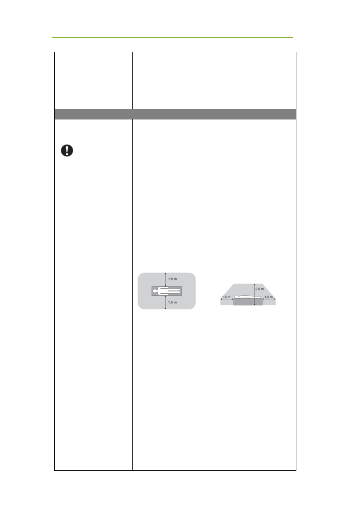
Do not place excessive weight on the device.
Otherwise, the internal image sensor may be damaged and
images may be incorrect
Uniform load:150 kg over the whole area of the detector
surface
Local load:100 kg on an area 4 cm in diameter
Be sure to use the equipment on a flat surface so it will not bend.
Otherwise, the internal image sensor may be damaged.
Be sure to securely hold the detector while using it in upright
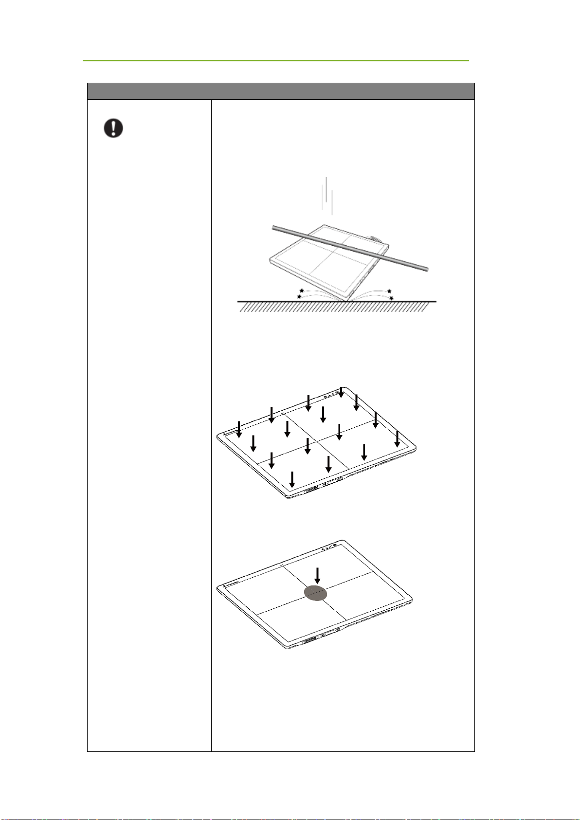
positions. Otherwise, the detector may fall over, resulting in injury
to the user or patient, or may flip over, resulting in damage to the
device.
Safety Information
iRay Technology Co. Ltd. 15
Keep the
same load
(the same
pressure)
on the
detector
when
acquiring
an image,
or the
image will be incorrect.
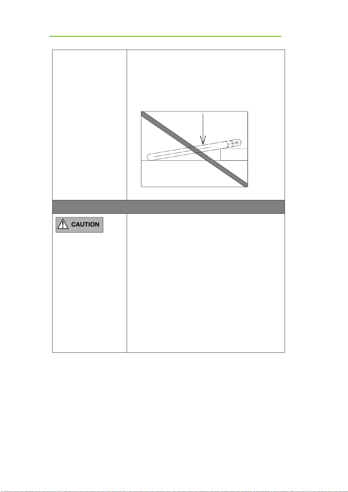
CAUTION
Do not operate close to fire, do not use in high temperatures
Do not invert positive and negative poles
Do not contact with metal in case of a short circuit
Do not insert sharp objects into the battery
Do not hit the battery
Do not stand on the battery
Do not use the battery for purposes other than those stipulated in
the rules
Do not dispose of the battery or change its internal structure
Do not submerge the battery in water; please keep it dry in
storage and do not contact with water while in use
Please charge the battery with the charger provided by
Manufacturer
Do not mix the battery with ones not provided by Manufacturer
Do not charge the battery with a broken charger.
Charge the battery regularly to avoid over-discharge failure.
Do not use the battery when it is severe ballooning.
1.2 Notes for Use
When using the device, take the following precautions. Otherwise, problems may occur and there
may be a malfunction.
Before exposure
Be sure to check the device daily and confirm that it works properly.
Be sure there is a battery installed in the product to avoid a sudden power off

Safety Information
iRay Technology Co. Ltd. 16
Sudden heating of the room in cold areas will cause condensation to form on the
device. In this case, wait until condensation evaporates before performing an
exposure. If it is used while condensation is formed, problems may occur in the
quality of captured images. When an air-conditioner is used, be sure to
raise/lower the temperature slowly so that a difference in temperature in the
room and the device does not occur, to prevent condensation.
The detector should be warmed for more than 20 minutes before exposure or
updating gain or defect template.
During exposure
Do not move the power cable during exposure as it may cause image noise or
artifacts, or even incorrect images.
Do not use the equipment near detectors generating strong magnetic fields.
Otherwise, it may cause image noise, artifacts or even incorrect images.
Do not make an exposure within 60 seconds after 4 full range exposures.
Otherwise, the image will be incorrect. Do not make an exposure within 30
seconds after a full-range exposure. The larger the dose used, the longer the
wait should be before the next exposure.
During image acquisition, product should not be influenced in a physical or
electrical way.
After exposure
If the detector will not be used for 5 days, it is required to take out the battery. If
the battery will not be used for a long time, it must be charged to 30%~50%
every 3 months or 50%~70% every 6 months.
Disinfecting and Cleaning
After every examination, wipe the patient contact surfaces with disinfectants
such as Benzalkonium chloride or Benzalkonium bromide, to prevent the risk of
infection. For details on how to sterilize the device, consult a specialist.
Do not spray the detector directly with disinfectants or detergents.
Wipe it with a slightly damp cloth with a neutral detergent. Do not use solvents
such as alcohol, thinner, benzene, acid and base. Doing so may damage the
surface of the detector.
It's recommended to use a waterproof non-woven cover as an isolated layer
between the detector and blooding patient.

General Description
iRay Technology Co. Ltd. 17
2 General Description
The product is a cassette-size wireless X-ray flat panel detector based on amorphous silicon thinfilm transistor technologies. It is developed to provide the highest quality of radiographic images,
and contains an active matrix of 2832×2836 with 150um pixel pitch. The detector’s scintillator has
two options: GOS (Gadolinium Sulfoxylate) and CsI (Caesium Iodide). However, the greatest
improvement is wireless communication between the detectors and PC. In addition, it can be
powered with a battery for portable panel use.
2.1 Scope
This manual contains information about the Mars1717XF. All operators must read and understand
this manual before using the device. All information in this manual, including illustrations, is based
on an equipment prototype. If your configuration does not have any of these items, information
about these items in the manual does not apply to your detector.
2.2 Lineup
Mars □ □- □
GSI: GOS; CSI: CSI
XF
1717: 17-inch X 17-inch
Mars series

General Description
iRay Technology Co. Ltd. 18
2.3 Characteristics
Wireless static Flat Panel Detector used for general radiography.
17 × 17 inch
AED trigger
Easy-to-change cable and charge in tray.
Battery rechargeable
IPX4
2.4 Intended Use
Wireless Digital Flat Panel Detector is intended for digital imaging solutions and designed to
provide general radiographic diagnosis of the human anatomy. It is intended to replace
radiographic CR and DR systems in all general-purpose diagnostic procedures. This device is not
intended for mammography or dental applications.
The detector can be used for general X-ray diagnosis of certain body parts. It is not intended for
mammography, dental applications, neonatal and fluoroscopy. More care should be taken when
making a diagnosis of people with allergies. In addition, it is also prohibited for use on pregnant
women. Shielding of none-inspection body areas is necessary during X-ray exposure. There is
no contraindication.
According to product’s intended use and results of risk management, essential performance is
identified and described as the following:
To acquire dark images, product shall be not influenced by imaging acquisition.
To maintain data transmission, product shall be not influenced by data and signal
transmission.
2.5 Product Components
The product is configured with the components below
Item
Description
General Description
iRay Technology Co. Ltd. 19
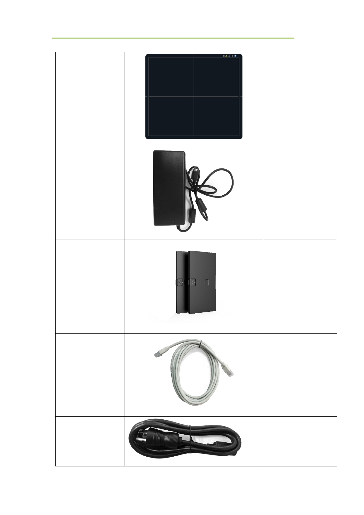
Mars1717XF Detector
Mars1717XF GSI/CSI
Medical adapter for
detector and battery
charger
24V (DC) power adapter
Battery pack
7.6V battery pack
Gigabit ethernet cable
Ethernet cable for
wireless router
AC power cable
AC cable for adapter
General Description
iRay Technology Co. Ltd. 20
Battery charger
Battery charger
User Manual
Paper print
CD-ROM
User Manual
Service tool
Note: The product package may be different based on requirements.
2.6 Components Description
2.6.1 Detector
External Signals Input and Control Panel
Control Panel
General Description
iRay Technology Co. Ltd. 21
NO.
Item
Description
A
DC Input Interface
24V DC input
B
Reserved
Reserved
C
Status Indicator
Detector Status indicator
D
Reserved
Reserved
E
Link Indicator
Detector Link indicator
F
Power Indicator
Detector Power indicator
G
Power Button
Power button
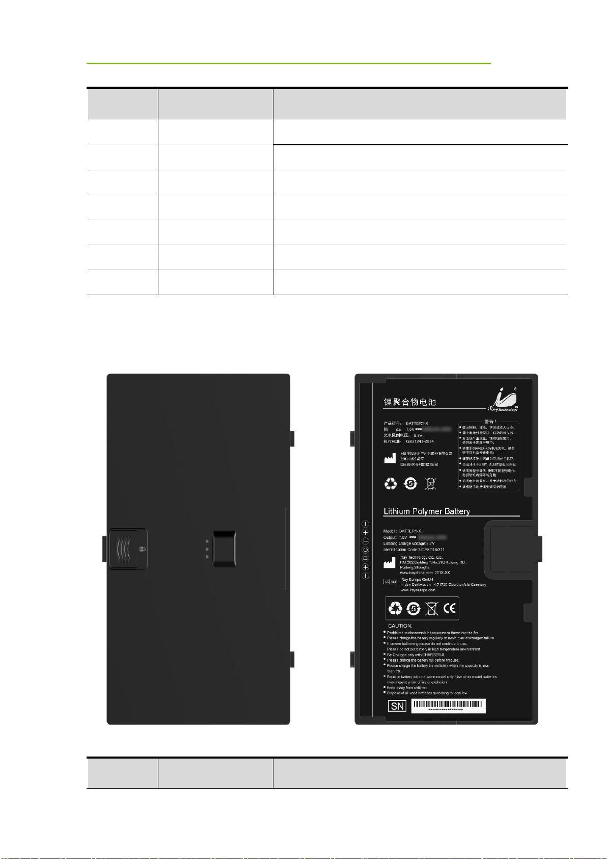
2.6.2 Battery Pack
NO.
Item
Description
D
E A B
C
General Description
iRay Technology Co. Ltd. 22
A
Battery Label
/ B Battery Interface
7-pin battery connector
C
Guide Block
/ D Latch
Attach the battery lock to the detector
E
Touch Display
Show battery level after touching
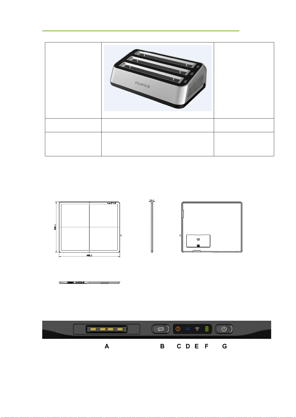
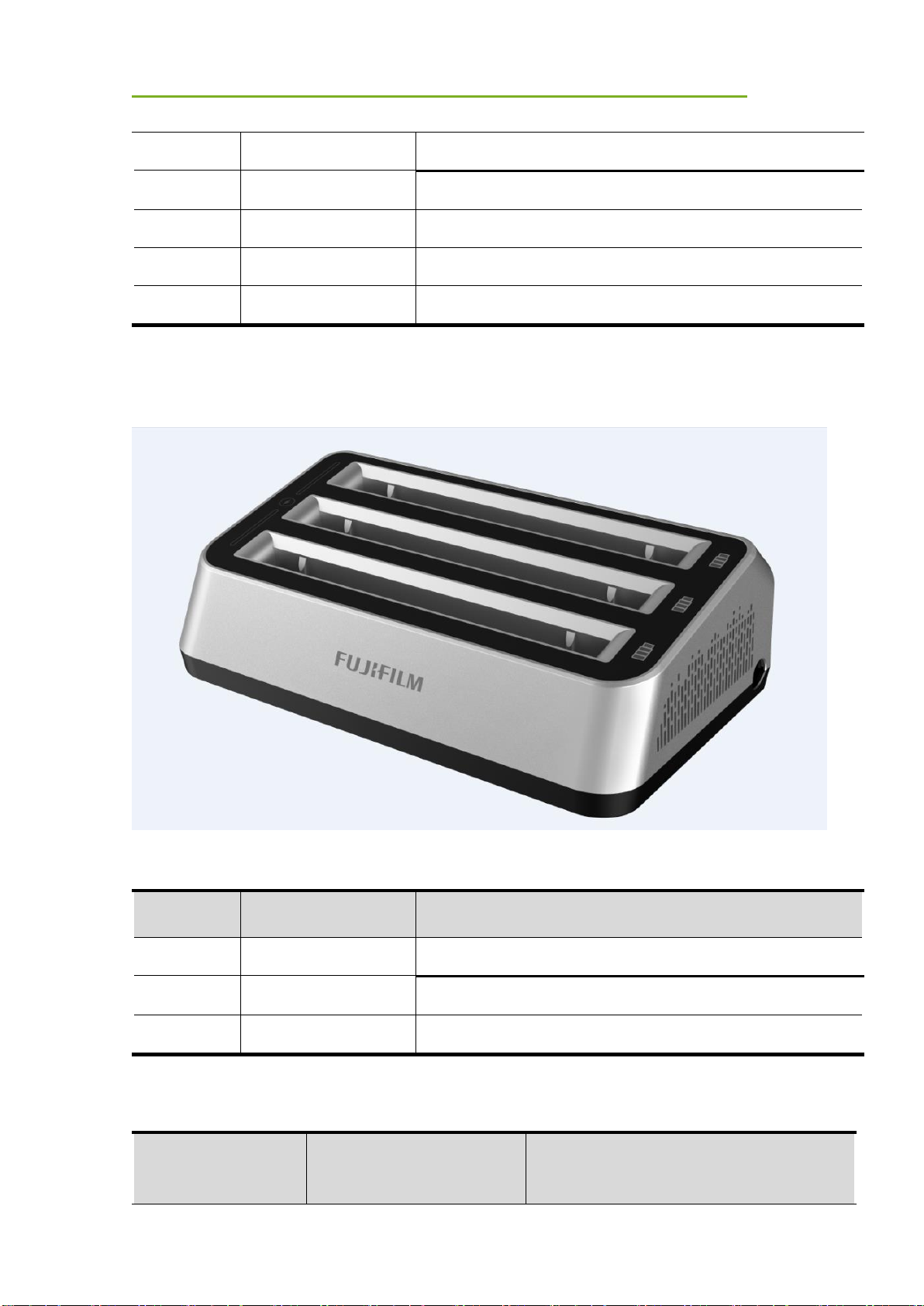
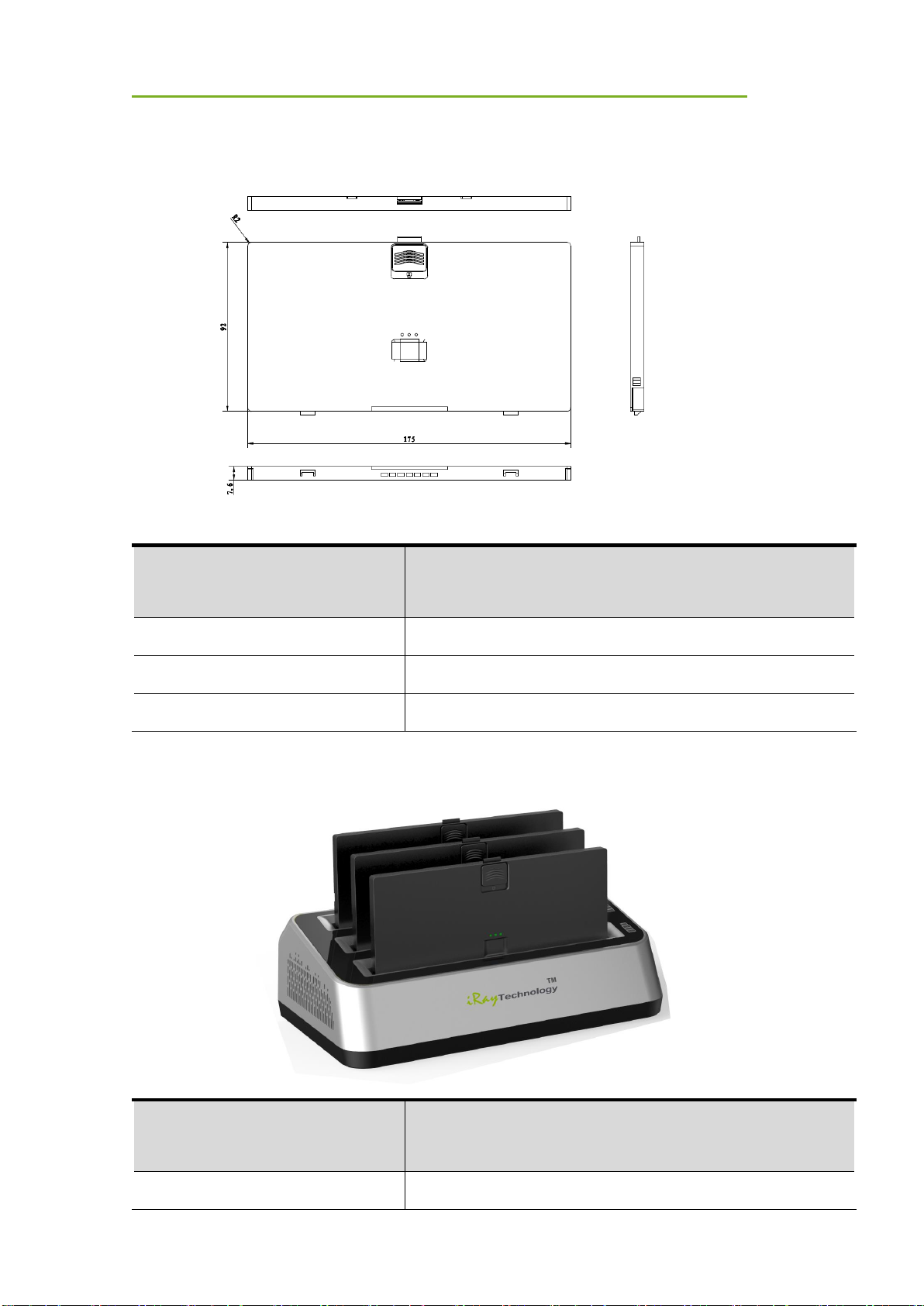
2.6.3 Battery Charger
Item
Item
Description
A
Battery Slot
3 batteries inserted
B
Capacity Indicator
The indicator definition is as below
C
DC Jack
24V DC input
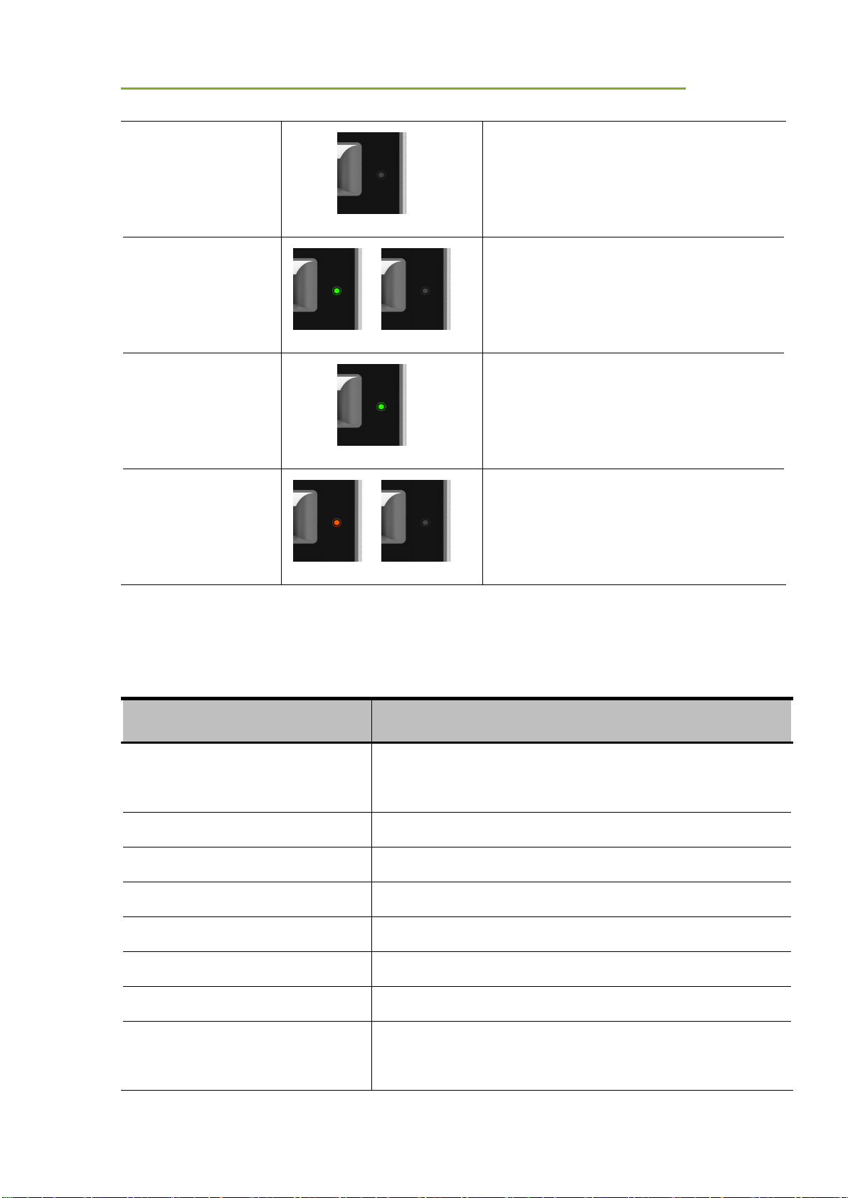
The battery charging capacity indicator definition:
Indicator
Lighting Status
Operating Status
B C A
General Description
iRay Technology Co. Ltd. 23
OFF No battery insert
Green blinking
Battery insert with capacity ≤95%, charging
Green ON
Battery insert with capacity >95%
Orange blinking
Battery slot malfunction
2.7 Product Specifications
2.7.1 Detector
Item
Specification
Model
Mars1717XF-GSI (GOS)
Mars1717XF-CSI (CsI)
Pixel Size
150 μm
Effective Array
2832 x 2836 (Note)
Effective Area (H x V)
424.8mm x 425.4mm
Greyscales
16 bit
Image Transfer
Wireless: IEEE802.11a/b/g/n
Wireless Frequency Range
2.412~2.472GHz, 5.18~5.22GHz; 5.745~5.85GHz
Data Transmission Power
13dBm (Typ.) @802.11a
16dBm (Typ.) @802.11b

General Description
iRay Technology Co. Ltd. 24
14dBm (Typ.) @802.11g
13dBm (Typ.) @802.11n HT20
11dBm (Typ.) @802.11n HT40
16dBm@2.4GHz
13dBm@5.8GHz
Wireless Modulation
11b: DSSS (DBPSK, DQPSK and CCK)
11a/g/n: OFDM (BPSK, QPSK,16QAM, 64QAM)
Wireless Band
2.4GHz≤40MHz
5.19GHz≤40MHz
5.8GHz≤40MHz
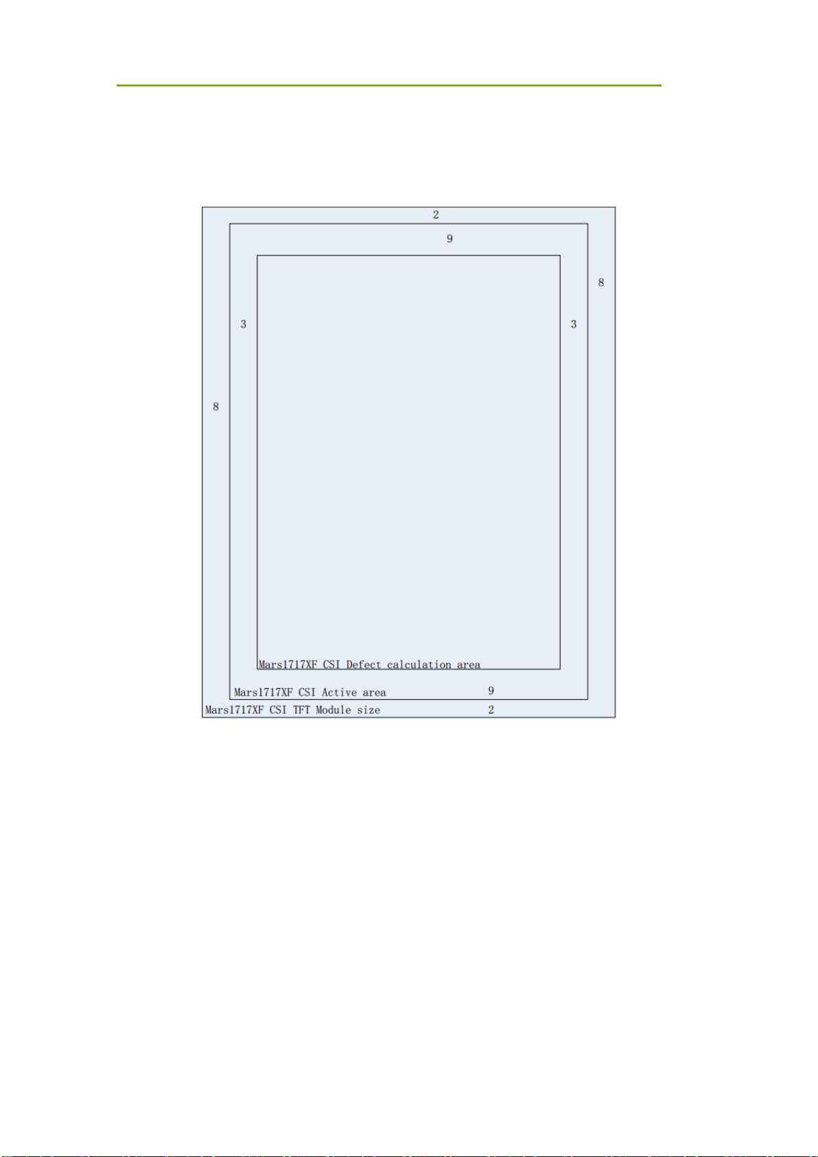
Note: The Mars1717XF-GSI’s active area and defect calculation area is 2832 x 2836; the TFT
module size is 2848 x 2840. Please see figure below
8
2
8
2Mars1717XF GSI TFT Module size
Mars1717XF GSI Active area && defect calculation area
General Description
iRay Technology Co. Ltd. 25
The Mars1717XF-CSI defect calculation area is 2826 x 2818, the active area is 2832 x 2836 and the
TFT module size is 2848 x 2840
General Description
iRay Technology Co. Ltd. 26
2.7.2 Battery
Item
Specifications
Model
Battery-KX
Rated Capacity
Min. 3500mAh, Typ.3800mAh @ Discharge 0.5C
Rated Voltage
7.6V
2.7.3 Battery Charger
Item
Specifications
Model
Charger-KX

General Description
iRay Technology Co. Ltd. 27
Simultaneous Charging
3 battery packs
Full Charging Time
2.5 hours
2.7.4 Environment
Temperature
Temperature
Variation
Humidity
Atmospheric
Pressure
Atmospheric
Pressure Variation
Operating
5~30℃
<1k/min
10%~80%
RH
700~1060hPa
<10kp/min
(1kp=1.0197E-5Pa)
Storage
(without
battery)
-20~50℃
<1k/min
10%~90%
RH
700~1060hPa
<10kp/min
(1kp=1.0197E-5Pa)
Detectors should operate at altitudes of not more than 3,000m; the requirement is only for the detector.
If storing with a battery, the temperature should be in the range of -20℃~45℃ when the expected
storage time is less than 3 months. For -20℃~25℃, the storage time is 12 months.

Operation
iRay Technology Co. Ltd. 28
3 Preparation
3.1 Detector Installation
3.1.1 Attach Battery Pack
The product can be powered by both a battery pack and DC power. Once the battery pack is
inserted or DC power is connected, detectors will be turned on immediately. If neither battery
nor DC power is connected, panel will power off. Please see below for battery installation.
Make sure that connectors on the battery pack
are pointed to the opening in the battery
compartment.
Slide battery package into battery compartment
(Make sure battery capacity overpass is 15%).
Slide the battery lock lever.
3.1.2 Booting Up
On the control panel, users can press the power button to turn on/off.

Operation
iRay Technology Co. Ltd. 29
When the detector is powered down, the user
presses the button for 4 seconds to turn on the
detector if the battery is inserted and the capacity
is not less than 15%, or DC power is connected.
When the detector is powered on, the user
presses the button for 4 seconds to shut down the
detector. On the other hand, it can also be used as
a reset internal control IC when the button is
activated for 8 seconds.
After booting up, users can check the indicator of the detector.
Power indicator
Power Indicator
Lighting Status
Status
Battery Capacity
DC Input
Description
OFF NO
NO
Detector is turned off
Orange ON
≥7% & ≤15%
NO
Detector is turned on
Green ON
>15%
NO
Detector is turned on
NO
YES
Orange Blinking
≥7% & <15%
YES
Detector is turned on
Green Blinking
≥15% & <95%
YES
Detector is turned on
or detector is in sleep
mode
Link indicator:
Link Indicator
Lighting Status
Description
OFF
Detector is turned off

Operation
iRay Technology Co. Ltd. 30
Wired connection broken and wireless
connection not ready
Blue ON
Wireless connection is enabled
Green ON
Wired connection is enabled (Service Mode)
Blue blinking
Detector Initialization
Wireless configuration reset
Green blinking
Wireless configuration reset
Mode indicator:
Mode Indicator
Lighting Status
Description
Blue ON
Default
OFF
Detector is turned off
Status indicator:
Status Indicator
Lighting Status
Description
OFF
Detector is turned off
Exposure prohibited
Green ON
Ready for exposure
Orange blinking
Safety Mode
Orange ON
Fatal Error

Operation
iRay Technology Co. Ltd. 31
Green blinking
Wireless configuration reset
3.1.3 Adapter
The detector supports an externally powered It gets CB certificate No. SG PSB-MD-00005 and
NRTL certificate No. U8V 093768 0016. Port defined as bellowing:
No.
Definition
Voltage Range
Rated Current
P1
DC Power Negative
0~0.5V
0~0.42A
P2
DC Power Positive
23~25V
0~0.42A
P3
DC Power Positive
23~25V
0~0.42A
P4
DC Power Negative
0~0.5V
0~0.42A
In order to meet the safety and function requirements of the detector, standard components are
recommended.
AC Adapter
4 Operation
The detector provides user SDK for integration into the DR system. Additionally, it also provides
application demonstration, i.e., iDetector.
4.1 Main Operation
The detector mainly acquires X-ray images. More importantly, the detector should build

Operation
iRay Technology Co. Ltd. 32
synchronization with the X-ray generator, i.e., Software Mode and AED Mode.
4.1.1 Software Mode
4.1.1.1 Block Diagram
Software mode builds the first X-ray image acquisition step. Please see the figure below for
general features. Software mode is configured by selecting “prep” in Trigger mode and
“prepcapmode_acq2” in Prep capmode.
The workstation hosts the PC device installed with FDR SE Console or iDetector. Chapter 3.3
describes how to establish connection between detectors and the workstation. In Software
mode, the workstation does not control the X-ray generator; users decide when to take an X-ray.
4.1.1.2 Work flow
Detector clears until warning message changes
from “Exposure prohibit” to “Exposure Enable”
Click “Acquire”
Shoot x ray in exposure window. But the longer
time user waits, the worse image would be
Wait for image uploaded

Operation
iRay Technology Co. Ltd. 33
4.1.1.3 Timing Setting
To get a clear view of the workflow, see the diagram below for details
Clear Exposure Acquisition
Detector
Anode
Rotate
Exposure Enable
X ray
shooting
Exposure
Prohibited
Workstation
Xray
Generator
Process
Exposure
Prohibited
1
2
3
4
5
6
7 8
9
10 11
12
1. Workstation receives “Acquire” request, send command “Clear” to detector.
2. Detector receives “clear” from workstation and begins flushing panel. Meanwhile,
replies to workstation “Exposure Prohibited”.
3. Detector finishes “Clear” and sends message “Exposure Enable”
4. “Exposure Enable” is shown on iDetector’s bar, user takes X-ray.
5. User triggers X-ray generator to initialize and do anode rotation to prepare for X-ray.
6. X-ray generator finishes preparation and replies to user
7. X-ray generator begins releasing X-ray
8. X-ray generator finishes taking X-rays.
9. Workstation prepares receiving image.
10. Detector begins data acquisition after time limits.
11. Detector completes image acquisition and begins image transmission.
12. Workstation receives all images.
Images received will be preview images; preview images are those without much correction which
causes some stripes; they cannot be used for final diagnosis.
The detector will make another dark image acquisition for offset correction. If Hardware Post offset
and Hardware calibration are selected, the detector uploads the processed image to the
workstation after offset, gain and defect calibration.
If Software Post offset and Software calibration are selected, the corrected image is shown on
the screen after the workstation finishes offset, gain and defect calibration.
Note: If the wireless condition is bad, the detector cannot send even one package in 30s. It will
stop trying to send image packages. Users have to retrieve images from the detector when the
wireless condition is good enough.

Operation
iRay Technology Co. Ltd. 34
4.1.2 AED Mode
4.1.2.1 Block Diagram
Please see the figure below for general features. AED mode is configured by selecting “inner” in
Trigger mode and “cycleacq” in inner trigger subflow.
The workstation hosts the PC device installed with FDR SE Console or iDetector. Chapter 3.3
describes how to establish the connection between detectors and the workstation. In AED mode,
the workstation does not control the X-ray generator; the user decides when to take the X-ray.
4.1.2.2 Work Flow
4.1.2.3 Timing Setting
To get a clear view of the workflow, see the diagram below for details
Wait for image uploaded
Take X-ray in exposure window.
Detector clears until warning message changes
from “Exposure prohibit” to “Exposure Enable”
Click “Acquire”

Operation
iRay Technology Co. Ltd. 35
Clear Exposure Acquisition
Detector
Anode
Rotate
Exposure Enable
X ray
shooting
Exposure
Prohibited
Workstation
Xray
Generator
Process
Exposure
Prohibited
1
2
3
4
5
6
7 8
11
9 10
12
1. Workstation receives “Acquire” request and sends “Clear” to detectors.
2. Detector receives “clear” from workstation and begins flushing panel. Meanwhile, replies to
workstation “Exposure Prohibited”.
3. Detector finishes “Clear” and sends message “Exposure Enable”.
4. “Exposure Enable” is shown on iDetector’s bar, user takes X-ray.
5. User triggers X-ray generator to initialize and do anode rotation to prepare for X-ray.
6. X-ray generator finishes preparation and replies to user
7. X-ray generator begins releasing X-ray
8. X-ray generator finishes taking X-rays.
9. Detector begins data acquisition after time limits.
10. Detector completes image acquisition and begins image transmission.
11. Workstation begins receiving all images.
12. Workstation finishes receiving all images.
Images received will be preview images. Preview images are those without much correction which
causes some stripes; they cannot be used for final diagnosis.
The detector will make another dark image acquisition for offset correction. If Hardware Post offset
and Hardware calibration are selected, the detector uploads the processed image to the
workstation after offset, gain and defect calibration.
If Software Post offset and Software calibration are selected, the corrected image is shown on
the screen after the workstation finishes offset, gain and defect calibration.
Note: If the wireless condition is bad, the detector cannot even send one package in 30 seconds.
It will stop trying to send an image package. Users have to retrieve images from the detector
when the wireless is good enough.

Operation
iRay Technology Co. Ltd. 36
4.1.2.4 Abnormal Action
If users do not want to take an X-ray, it is possible to cancel the exposure window manually.
4.1.2.5 Exposure Window
The exposure window can be configured with: 0.7s, 1.2s, 2.2s, 3.2s, 4.2s.
4.2 Connection Build
Open iDetector and click “Connect”
based on product name
Notes:
1. Users must re-connect the detector with a different IP address when changing the
connection from a different net card.
2. Switching between wired and wireless connection does not need any extra operation.
3. The rule of multi-share is based on the IP address. The second terminal with a different
IP address is not allowed to operate when the first is connected. If there is no command
transmission between the detector and the workstation (FDR SE Console or iDetector) over
5 minutes, the detector releases access authority.
4.3 Panel Configuration
Choose iDetector menu-related modules

Operation
iRay Technology Co. Ltd. 37
“Acquire” module:
Choose offset mode, load gain and
defect template
Acquire images: “Prepacq”, “Acquire”
and so on
“SDK” module:
IP address, MAC address and so on
“Detector” module:
Trigger module, wireless configuration
and so on

Operation
iRay Technology Co. Ltd. 38
“Calibrate” module:
Template generation and management.
“Local File” module:
Read raw or dcm image
4.4 Correction Template Generation
Manufacturer recommends users correction template generation after installation, any major
change on system settings or hardware configuration. On the other hand, it is also
recommended to do template generation every 6 months.
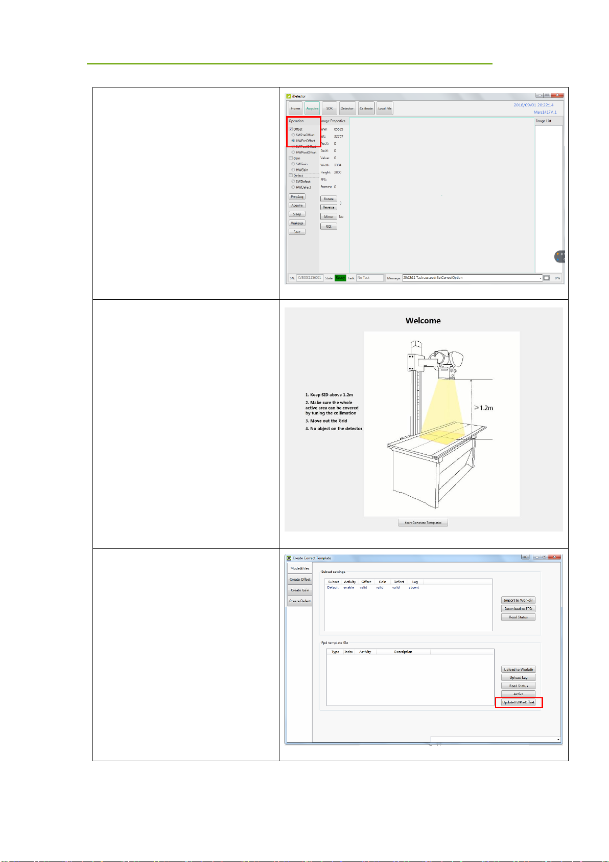
4.4.1 Pre-offset Template Generation
The pre-offset template is necessary for preview image. See below
Operation
iRay Technology Co. Ltd. 39
Go to “Acquire” module, choose
“HWPostOffset”
Go to “Calibrate” module, click “Start
Generate Templates”
Click “UpdateHWPreOffset”, wait until
image acquisition ends

Operation
iRay Technology Co. Ltd. 40
4.4.2 Gain Template Generation
Before gain template generation, make sure SID=1.2m; no copper is required,
Go to “Acquire” module, choose
“HWPostoffset”
Go to “Calibrate” module, click “Start
Generate Templates”

Operation
iRay Technology Co. Ltd. 41
Click “ Create Gain”
Click “Start”
Set X-ray dose to meet the expected
value.
Click “PREP”, wait for exposure bar to
count down. Before window ends, take
X-ray.

Operation
iRay Technology Co. Ltd. 42
There will be a prompt in the region of
the current value if the dosage is
incorrect. (Note 1)
Change dosage and exposure again
until image is accepted.
Click “Accept” if box is green,
Click “PREP” to start another X-ray
take.
Gain calibration template needs 5 X-
ray images.
After 5 images acquired, click
“Generate”, wait until “Task
succeed:FinishGenerationProcess”
Note:
1. X-ray image has three states: green, yellow and red.
Green means image meets requirements.

Operation
iRay Technology Co. Ltd. 43
Yellow means image does not meet requirements, but can generate template.
Red means image does not meet requirements, cannot generate template, must be
taken again.
4.4.3 Defect Template Generation
Before defect template generation, make sure SID=1.2m, no copper is required,
Click” Create Defect”
Click “Start”, Defect template needs 8
X-ray images.

Operation
iRay Technology Co. Ltd. 44
Set X-ray dose according to expected
value.
Click “prep”, wait for exposure bar to
count down. Before window ends, take
X-ray.
There will be a prompt in the box if the
dosage is improper. (Note 1)
Change dosage and exposure again
until image is accepted.
Click “Accept” if box is green,
Click “PREP” to start another X-ray
take.

Operation
iRay Technology Co. Ltd. 45
Calibration template needs 8 X-ray
images.
After images acquire, click “Generate”,
wait until “Task
succeed:FinishGenerationProcess”
. Note:
1. X-ray image has three states: green, yellow and red.
Green means image meets requirements.
Yellow means image does not meet requirements, but template can be generated.
Red means image does not meet requirements, template cannot be generated, must
take another shot.
4.5 Image Check and Upload
“Local Image Check” defines the function checking image saved in the workstation (FDR SE
Console or iDetector). “Panel Image Upload” defines function uploading images stored in the
detector.
4.5.1 Local Image Check
Choose “Local File”

Operation
iRay Technology Co. Ltd. 46
Click “Local File” to open dicom, Raw
and tif file
Click “Open”
/
4.5.2 Panel Image Upload
Double-check firewall is closed
Panel Image is uploaded as below.

Operation
iRay Technology Co. Ltd. 47
Choose “Detector” -> “Images”
Click “Query Images”, image info listed
below
Click “Upload Images”
Input the index number of images
Click “OK”
Waiting for status from "Busy" into
"Ready"
Check upload images
Click "Stop Uploading" to stop image
upload
Images uploaded is stored in "work_dir \
Mars1717XF_Client \ upload \serial
number"

Operation
iRay Technology Co. Ltd. 48
4.5.3 Defect Template Check and Modification
iDetector provides function checking defect template. If the defect template has updates, the
user can add and delete defect pixels or lines.
4.5.3.1 Defect Template Check
Select “Local File” module
Click “Local File”
Choose template type “*.dft”, open it
4.5.3.2 Defect Template Modification
Open defect template

Operation
iRay Technology Co. Ltd. 49
If there are new defect pixels, type in
coordinates, click "Add".
If defect templates have dummy lines,
type in coordinates, click "Delete".
If there are new defect lines, type in
starting and ending coordinates, click
"Add".
If defect templates have dummy lines,
type in coordinates, click "Delete".
Click "Save" to save modified defect
template.
4.6 Correction Template Management
4.6.1 Template Synchronization
The detector supports correction template storage, which means templates can be transmitted
not only from the detector to the workstation(FDR SE Console or iDetector), but also from the
workstation(FDR SE Console or iDetector) to the detector.

Operation
iRay Technology Co. Ltd. 50
Make sure the firewall is turned off
Choose “Calibrate”,
Click “Start Generate Templates”
Click “Read Status” besides “Subset
settings”

Operation
iRay Technology Co. Ltd. 51
Click the template to be downloaded
Click “Download to FPD”
Check whether information is right.
Change Index in FPD if necessary.
Click “Download”.
Wait until “Task succeed: Download
CaliFile”

Operation
iRay Technology Co. Ltd. 52
Click “Read Status” to read template
Choose template number according to
requirements
Click “Active” to activate template
Upload templates
Make sure firewall is turned off

Operation
iRay Technology Co. Ltd. 53
Choose “Calibrate”,
Click “Start Generate template”
Click “Read status” besides FPD
template file.
Click template which needs to be
uploaded.
Click subset settings
Click “upload to Workdir”.
If information listed is right, click “OK”.
Wait until “Upload FPD file succeed!”

Operation
iRay Technology Co. Ltd. 54
Check template uploaded in
“work_dir\Mars1717XF_192.168.100.8\
Correct\Default”
4.6.2 Correction Activation
The detector supports two ways to do corrections. Software correction defines a scenario in
which the workstation(FDR SE Console or iDetector) finishes a correction. If the detector does
itself, that is hardware correction and calibration.
4.6.2.1 Software Correction
Make sure templates are saved in
“work_dir\Mars1717XF_192.168.100.8\
Correct\Default”
Choose “Acquire”

Operation
iRay Technology Co. Ltd. 55
Offset mode “SWPostOffset”,
Gain mode “SWGain”,
Defect mode “SWDefect”
4.6.2.2 Hardware Correction
Click “Read Status” to read template

Operation
iRay Technology Co. Ltd. 56
Choose template number according to
requirements
Click “Active” to activate template
Offset mode “HWPostOffset”
Gain mode “HWGain”
Defect mode “HWDefect”
/
4.7 Firmware Update
The detector supports firmware updating with the website; if the user needs to update firmware,
please follow the steps below
Preparation before updating
Go to page “Detector”
Operation
iRay Technology Co. Ltd. 57
Change Trigger mode to
“TriggerMode_Prep”
Change Prep Capmode to
“PrepCapMode_Acq2”
Click “Write”
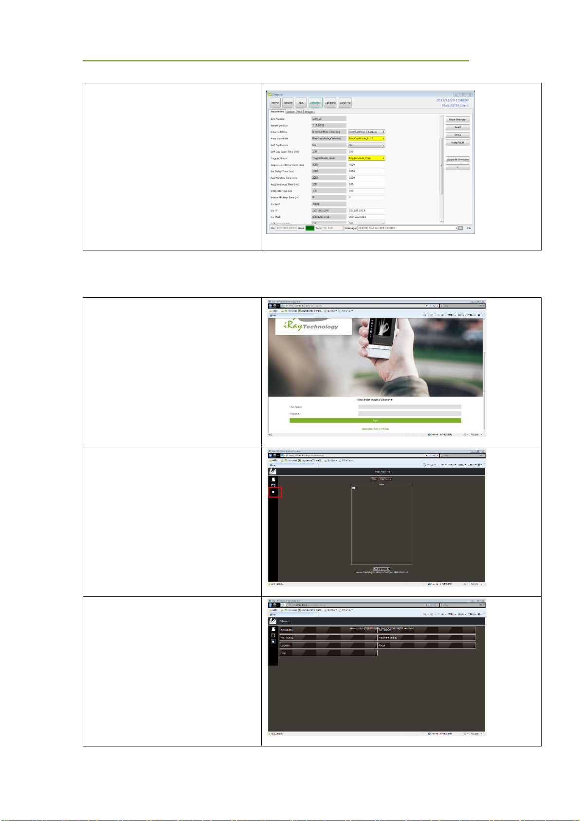
Firmware updating
Open IE browser.
Input 192.168.100.8
User name: admin
Password: iray
Click button in red box
Choose “upgrade”

Operation
iRay Technology Co. Ltd. 58
Click “browse” on the right
Choose”
Mars1717XF_IMAGE_41_ALL_XXXX
_XX_XX.ifrm”
Click “upgrade”
Click “close” when “upload image
success” pops up
Wait until upgrade is done.
Note:
1. Please insert the battery (more than 25%) in the detector, in case power is down when
upgrading. On the other hand, the detector should reboot after updating.
4.8 Short cut
iDetector supports some shortcuts as follows:
Double-click left mouse: image displayed in center with maximum size.
Press and drag left mouse: drag image displayed.
“F3”: Quickly adjust the image window width and window level.

Operation
iRay Technology Co. Ltd. 59
4.9 Software
4.9.1 Main GUI
Double-click iDetector, main interface is shown on the screen. See the table below for a detailed
function description.
Item
Function description
Home
Connect detector, check connection status
Acquire
Image acquisition, correction mode, image storage and processing
SDK
Config.ini setting and Log level setting
Detector
Detector configuration, synchronization methods, etc.
Calibrate
Correction template generation and management
Local File
Local image check and image processing
4.9.2 Home Page
Item and button description are shown as follows.
Item
Function description
Name
Detector name
SN
Detector SN number

Operation
iRay Technology Co. Ltd. 60
Product Type
Product type
State
Three states: Bind, Unknown, Ready
Button
Function description
Connect
Build connection with specific detector
Close
Disconnect with specific detector
Add
Add additional working directory
Remove
Delete working directory
4.9.3 Acquire Page
This page works mainly for image acquisition. In the “operation” box, the user chooses the
image correction method according to requirements. “image properties” shows simple
information of the image acquired. “Image list” shows the last 5 images; if the user wants to
check an image, then double click. The user can rotate images and do other image processing
with “ROI”.
Figure 4.13.2
The state of the detector, SN and Message is on the bottom of the page.
Item
Function description
SN
Connected detector SN number

Operation
iRay Technology Co. Ltd. 61
State
Detector status, such as Busy or Ready
Task
What detector is doing
Message
Feedback of detector action, such as succeeded or failed
Image operation and property of SDK is shown below
Correction Menu
Function description
Offset
SWPreOffset
Reserved
HWPreOffset
Reserved
SWPostOffset
DR Software does post offset correction
HWPostOffset
Detector does post offset correction
Gain
SWGain
DR Software does gain correction
HWGain
Detector does gain correction
Defect
SWDefect
DR Software does defect correction
HWDefect
Detector does gain correction
Acquisition
Functional description
PrepAcq
Flush the panel and then do image acquisition
Acquire
Start image acquisition
Stop
Stop continuous image acquisition
Save
Save images
SeqSaveSet
Save image frames in continuous image acquisition mode
(document type and path can be set)
Image Properties/
Image Process
Functional description
WW
Window width
WL
Window level
PosX
Cursor X coordination
PosY
Cursor Y coordination
Value
Value of cursor
Width
Image width

Operation
iRay Technology Co. Ltd. 62
Height
Image height
FPS
Frame rate
Frames
Frame number
Rotate
Rotate image 90 degrees in clockwise direction
Reverse
Rotate image 90 degrees in counterclockwise direction
Mirror
Mirror image horizontally
ROI
Statistic of image such as AVG and SV
Image List
Latest 5 images
Image preview shortcut is stated below:
• Double left click: image displayed in center with maximum size.
• Double right click: window level and width adjusted to WL: 32767/WW: 65535.
• Drag left mouse: drag image displayed.
• Lateral drag right mouse: adjust window width
• Vertical drag right mouse: adjust window level
• F3: Quickly adjust window width and level.
Note: correlation between image acquired and physical panel direction
Image
Panel
A A B D C C D
B

Operation
iRay Technology Co. Ltd. 63
4.9.4 SDK Page
The page is used to configure config.ini and set log level in real time, as shown below
A
B
C
D
D
C B A

Operation
iRay Technology Co. Ltd. 64
4.9.5 Detector Page
4.9.5.1 Parameters
Parameter tab is activated in default. Five boxes on the page are defined as follows:
Zone 1: parameters
Zone 2: parameters reading from detector
Zone 3: parameters written into detector
Zone 4: function button
Zone 5: simple message from detector and state

Operation
iRay Technology Co. Ltd. 65
Configuration parameter items
ParmName
Description
Modifiable
Main Version
Detector FPGA version
NO
Read Version
Detector Read version
NO
Product No
Product number
NO
SN
Serial number
NO
Trigger Mode
Static X-ray synchronization mode
YES
Fluro Sync
Dynamic X-ray synchronization mode
YES
Set Delay Time
Delay time for “prepacq”
YES
Acquire Delay
Reserved
YES
Integrate Time
Reserved
YES
Tube Ready
Reserved
YES
Function button description
Function Button
Description
Reset Detector
Reboot detector

Operation
iRay Technology Co. Ltd. 66
Read
Read configuration
Write
Write configuration
Upgrade Firmware
Reserved
4.9.5.2 Sensor
This page includes temperature and humidity information.
Sensor
Description
Modifiable
Temperature
Read temperature in detector
NO
Humidity
Read humidity in detector
NO
4.9.5.3 Wireless configuration
Mode should be checked with client.

Operation
iRay Technology Co. Ltd. 67
Parameters
Description
Client
Add
Add default SSID in wifi list
Del
Delete specified SSID in wifi list
Up
Move up
Down
Move down
Select
Set specified SSID as default one which means it will be loaded
automatically after powering up
SSID Key
List 10 optional SSID names
Others
Read Config
Read wireless configuration from detector
Write Config
Write wireless configuration to detector
Read WiFi Status
Check wireless link status in detector
Scan from FPD
Scan SSID in air with FPD wifi module
Wifi Status Info
Wireless link status is shown in this area
Wireless Network
Available wireless networks are shown in this area

Operation
iRay Technology Co. Ltd. 68
4.9.5.4 Images
Parameters
Description
Query images
Query image list in detector
Upload images
Upload specific images in detector
Stop upload
Stop uploading accidently
Index
Item No. which is roll counting
Filename
Image No. which is defined and saved in detector
Create time
Time image is saved
Delay time
Acquisition delay time
Image attr
Image type
Note:
1. If “HWPostoffset” is chosen, the image saved in the detector will be the corrected one. If not
or “SWPostoffset” is chosen, it will be the incorrect one.

Operation
iRay Technology Co. Ltd. 69
4.9.6 Calibrate Page
This page works for template management and generation.
Function Button
Description
Start to Generate Templates
Start template generation and template management
4.9.7 Local File Page
This page works for local image check.

Operation
iRay Technology Co. Ltd. 70
Function Button
Description
Rotate
Rotate image 90 degrees in a clockwise direction
Reverse
Rotate image 90 degrees in a counterclockwise direction
Mirror
Mirror image horizontally
ROI
Region of interest image statistic such as AVG and SV
Right press mouse, draw a box
4.10 IT-network
4.10.1 Purpose for IT-network
Transmission between the detector and the workstation(FDR SE Console or iDetector) is image
data and command/status communication.
4.10.2 Required characteristics
Wireless communication follows IEEE 802.11a/b/g/n protocol. It works on 2.4GHz and 5GHz.
It supports at least 2 routers.
4.10.3 Required configuration
The wireless card and the detector must work on the same IP segment such as
192.168.100.XXX
They must support IEEE 802.11.a/b/g/n.
4.10.4 Technical specifications(Only for CE)
Image Transfer
Wireless: IEEE802.11a/b/g/n
Wireless frequency range
2.412~2.472GHz, 5.18~5.22GHz;5.745~5.85GHz
Data Transmission Power
13dBm (Typ.) @802.11a
16dBm (Typ.) @802.11b
14dBm (Typ.) @802.11g
13dBm (Typ.) @802.11n HT20
11dBm (Typ.) @802.11n HT40

Operation
iRay Technology Co. Ltd. 71
16dBm@2.4GHz
13dBm@5.8GHz
Wireless Modulation
11b: DSSS (DBPSK, DQPSK and CCK)
11a/g/n: OFDM (BPSK, QPSK,16QAM, 64QAM)
Wireless Band
2.4GHz≤40MHz
5.19GHz≤40MHz
5.8GHz≤40MHz
4.10.5 Intended information flow
The detector sends image data acquired to the workstation (FDR SE Console or iDetector). The
workstation(FDR SE Console or iDetector) sends users’ commands to the detector.
4.10.6 Hazardous Situations Resulting from Failure of the IT Network
Failure of completing essential performance
Failure of finishing configuration of product
Operating system is not compatible
Change or update software failed
Compatibility of interface
Data transfer protocol error
Inconsistency of interface or format leads to data distortion;
Data output failed;
4.10.7 Warning
Connection of the main unit to an IT-network that includes other equipment can result in
previously unidentified risks.
The manufacturer of the X-ray machine should identify, analyze, evaluate and control these
risks.
Subsequent changes to the IT-network can introduce new risks and require additional
analysis.

Operation
iRay Technology Co. Ltd. 72
4.10.8 Changes to IT Network Include:
changes in IT network configuration;
connection of additional items to IT network;
disconnecting items from IT network;
update of equipment connected to IT network.

Charger Installation
iRay Technology Co. Ltd. 73
5 Charger Installation
Insert battery into battery charger
Note: Insert direction as in figure
Make sure the battery is inserted to the bottom of
the opening
Unload battery from charger after charging
completes.

Regulatory Information
iRay Technology Co. Ltd. 74
6 Regulatory Information
Product safety regulatory information includes safety of the detector, charger and other
accessories.
6.1 Manufacturer’s Information
COMPANY: iRay Technology Co., Ltd
ADDRESS: Rm. 202, Building 7, No. 590, Ruiqing Rd., Zhangjiang East,
Pudong, Shanghai, China
ZIP CODE: 201201
TELEPHONE: +86-21-50720560
European Representative
COMPANY: iRay Europe GmbH
ADDRESS: In den Dorfwiesen 14, 71720 Oberstenfeld Germany
www.irayeurope.com
TEL: +49-7062-977 88 00
FAX: +49-7062-976 05 71
Email: S.feng@iraychina.com
6.2 Medical Equipment Safety Standards
Medical equipment classification
Protection type against electrical shock
Class I equipment, using medically approved adaptor
supply
Internally powered equipment, using battery power supply
Protection degree against electrical shock
B Type
Note1
Protection degree against water
penetration
IPX4 (Detector)
IPX0 (Charger-KX)

Regulatory Information
iRay Technology Co. Ltd. 75
Mode of operation
Continuous operation
Flammable anesthetics
Not suitable for use in situation with flammable anesthetic
mixture with air, oxygen or nitrous oxide
Not suitable for use in oxygen-rich situation
The detector has two power supply modes (power adaptor and battery pack) and a single way for
signal transmission (wireless)
Note 1.When connected to patient, it was only allowed be powered by battery and shall
disconnect adapter cord
Safety standards reference
Wireless detector safety standards cover the detector, charger, battery pack and other
accessories.
MDD (93/42/EEC)
Medical Device Directive
Directive 2011/65/EU
substances (RoHS)
EN ISO 13485:2016
Medical devices– Quality management
systems– Requirements for regulatory purposes
EN ISO14971: 2012
Medical device – Application of risk
management to medical devices
IEC 60601 1: 2005 + CORR. 1 (2006) + CORR. 2 (2007) + AM1
(2012)
Medical electrical equipment –Part 1: General
requirements for basic safety and essential
performance
EN 60601-1:2006+A11:2011+A1:2013+A12:2014
Medical electrical equipment – Part 1: General
requirements for basic safety and essential
performance
BS EN 60601-1:2006+A11:2011
Medical electrical equipment –Part 1: General
requirements for basic safety and essential
performance
ANSI/AAMI ES60601-
1:2005/(R)2012+A1:2012+C1:2009/(R)2012+A2:2010/(R)2012
Medical electrical equipment – Part 1: General
requirements for basic safety and essential
performance
CAN/CSA-C22.2 No.60601-1:14
Medical electrical equipment –Part 1: General
requirements for basic safety and essential
performance

Regulatory Information
iRay Technology Co. Ltd. 76
KS C IEC 60601-1
Medical electrical equipment –Part 1: General
requirements for basic safety and essential
performance
JIS T0601-1:2012
Medical electrical equipment– Part 1: General
requirements for basic safety and essential
performance
SS-EN 60601-1:2006+A11:2011+A1:2013+AC1:2014+A12:2014
Medical electrical equipment – Part 1: General
requirements for basic safety and essential
performance
IEC 60601-2-54:2009+A1:2015
Medical electrical equipment –Part 2-54:
Particular requirements for the basic safety and
essential performance of X-ray equipment for
radiography and radioscopy
CAN/CSA-C22.2 NO. 60601-2-54:11
Medical electrical equipment –Part 2-54:
Particular requirements for the basic safety and
essential performance of X-ray equipment for
radiography and radioscopy
KS C IEC 60601-2-54:2012
Medical electrical equipment –Part 2-54:
Particular requirements for the basic safety and
essential performance of X-ray equipment for
radiography and radioscopy
SS-EN 60601-2-54:2010+A1:2015
Medical electrical equipment –Part 2-54:
Particular requirements for the basic safety and
essential performance of X-ray equipment for
radiography and radioscopy
IEC 60601-1-6:2010+A1:2013
Medical electrical equipment Part 1-6: General
requirements for basic safety and essential
performance — Collateral standard: Usability
CAN/CSA-C22.2 NO. 60601-1-6:11+A1:2015
Medical electrical equipment Part 1-6: General
requirements for basic safety and essential
performance — Collateral standard: Usability
KS C IEC 60601-1-6:2011
Medical electrical equipment Part 1-6: General
requirements for basic safety and essential
performance — Collateral standard: Usability
EN 60601-1-6:2010+A1:2015
Medical electrical equipment Part 1-6: General
requirements for basic safety and essential

Regulatory Information
iRay Technology Co. Ltd. 77
performance — Collateral standard: Usability
EN 60601-1-2:2015
Medical electrical equipment – Part 1-2: General
requirements for basic safety and essential
performance– Collateral standard:
Electromagnetic disturbances– Requirements
and tests
IEC 62133:2012
Secondary cells and batteries containing
alkaline or other non-acid electrolytes –
Safety requirements for portable sealed
secondary cells, and for batteries made
from them, for use in portable applications
EN 62220-1:2004
Medical electrical equipment – Characteristics of
digital X-ray imaging devices–Part 1:
Determination of the detective quantum
efficiency
EN 62304:2006/AC:2008
Medical device software – Software life-cycle
processes
EN 62366:2008
Medical devices – Application of usability
engineering to medical devices
ANSI/AAMI ES60601-1:2005+ Amendment 1:2012+ Amendment
2:2010
Medical Electrical Equipment – Part 1: General
requirements for safety and essential
performance
CAN/CSA C22.2 No. 60601-1-14
Medical Electrical Equipment – Part 1: General
requirements for safety and essential
performance
ISO 15223-1:2016
Medical devices-symbols to be used with
medical device labels, labeling and information
to be supplied–Part1:General requirements
6.3 Guidance and manufacture’s declaration for EMC
6.3.1 EMI Compliance Table
Emissions
Phenomenon
Compliance
Electromagnetic environment
RF emissions
CISPR 11
Group 1, Class B
Professional healthcare facility environment
Harmonic distortion
IEC 61000-3-2
Professional healthcare facility environment

Regulatory Information
iRay Technology Co. Ltd. 78
Class A
Voltage fluctuations
and flicker
IEC 61000-3-3
Compliance
Professional healthcare facility environment
6.3.2 EMS Compliance Table
Enclosure Port
Phenomenon
Basic EMC standard
Immunity test levels
Professional healthcare facility environment
Electrostatic
Discharge
IEC 61000-4-2
±8 kV contact
±2kV, ±4kV, ±8kV, ±15kV air
Radiated RF EM field
IEC 61000-4-3
3V/m
80MHz-2.7GHz
80% AM at 1kHz
Near fields from RF
wireless
communications
equipment
IEC 61000-4-3
Refer to table “Near fields from RF wireless
communications equipment”
Rated power
frequency magnetic
fields
IEC 61000-4-8
30A/m
50Hz or 60Hz
Near fields from RF wireless communications equipment
Test frequency
(MHz)
Band
(MHz)
Immunity test levels
Professional healthcare facility environment
385
380-390
Pulse modulation 18Hz, 27V/m
450
430-470
FM, ±5kHz deviation, 1kHz sine, 28V/m
710
704-787
Pulse modulation 217Hz, 9V/m
745
780
810
800-960
Pulse modulation 18Hz, 28V/m
870
930

Regulatory Information
iRay Technology Co. Ltd. 79
1720
1700-1990
Pulse modulation 217Hz, 28V/m
1845
1970
2450
2400-2570
Pulse modulation 217Hz, 28V/m
5240
5100-5800
Pulse modulation 217Hz, 9V/m
5500
5785
Input a.c. power port
Phenomenon
Basic EMC
standard
Immunity test levels
Professional healthcare facility environment
Electrical fast
transients/burst
IEC 61000-4-4
±2 kV
100kHz repetition frequency
Surges
Line-to-line
IEC 61000-4-5
±0.5 kV, ±1 kV
Surges
Line-to-ground
IEC 61000-4-5
±0.5 kV, ±1 kV, ±2 kV
Conducted
disturbances induced
by RF fields
IEC 61000-4-6
3V, 0.15MHz-80MHz
6V in ISM bands between 0.15MHz and 80MHz
80%AM at 1kHz
Voltage dips
IEC 61000-4-11
0% U
T
; 0.5 cycle
At 0º, 45º, 90º, 135º, 180º, 225º, 270º and 315º
0% U
T
; 1 cycle
and
70% U
T
; 25/30 cycles
Single phase: at 0º
Voltage interruptions
IEC 61000-4-11
0% U
T;
250/300 cycles
Recommended separation distances between portable or mobile RF communication
device and detector:
Portable RF communications equipment, including antennas, can effect medical electrical
equipment. The warning should include a use distance such as “be used no closer than 30 cm
(12 inches) to any part of the [ME EQUIPMENT or ME SYSTEM], including cables specified by
the manufacturer”.

Regulatory Information
iRay Technology Co. Ltd. 80
Cable provided for EMC
Cable
Recommended
length
Shield/Unshielded
Number
Cable classification
AC power cable
1.8m
Unshielded
1 piece
AC power
DC power cable
3m
Unshielded
1 piece
DC power
Electromagnetic Compatibility (EMC)
The Mars1717XF series wireless flat panel detector needs special precautions regarding EMC,
and should be installed by authorized personnel and follow EMC guidance in the user manual.
The Mars1717XF series product when in use may interfere with portable and mobile RF
communication devices such as mobile (cellular) telephones. Electromagnetic interference may
result in incorrect operation of the system and a potentially dangerous situation.
The Mars1717XF series wireless flat panel detector should not be stacked with or adjacent to
other devices. If inevitable, verify the detector.
The Mars1717XF series wireless flat panel detector conforms to this EN60601-1-2:2007
standard on both immunity and emissions.
Accessories, transmitters and cables other than those specified by the user manual or sold
together with product may result in increased emissions or decreased immunity of the detector.
6.4 Radio Frequency Compliance Information
Country
Item
U.S.A.
KDB 865664 D01
47 CFR part 15, subpart B
47 CFR part 15,subpart C 15.247
47 CFR part 15,subpart C 15.407
47 CFR §2.1091
KDB447498 D01 General Exposure Guidance v06
European Union
EN 301 489-1 V 2.1.1
EN 301 489-17 V 3.1.1
EN 300 440 V 2.1.1
Regulatory Information
iRay Technology Co. Ltd. 81
EN 300 328 V 2.1.1;
EN 301 893 V 2.1.1
EN 62311:2008
EN 62209-2:2010
EN 50566:2017
EN 62476:2010
EN 55032:2015
EN 61000-3-2:2014
EN 61000-3-3:2013
6.5 Battery Safety Standards
Standards
Description
UL1642
Component recognition on secondary Li-ion cells
UL 2054:2004 R9.11
Household and commercial batteries
IEC 62133:2012
Secondary cells and batteries containing alkaline or other non-
acid electrolytes
UN38.3
United Nations Recommendations on the Transport of
dangerous goods Manual of tests and Criteria
ST/SG/AC.10/11/Rev.5/Amend.1&Amend.2
6.6 Product Label
Mars1717XF-GSI Detector Label

Regulatory Information
iRay Technology Co. Ltd. 82
Mars1717XF CSI Detector Label
Battery Charger Label

Regulatory Information
iRay Technology Co. Ltd. 83
Battery Label

Regulatory Information
iRay Technology Co. Ltd. 84

Trouble shooting
iRay Technology Co. Ltd. 85
7 Troubleshooting
Please refer to the service manual. If the problem remains unsolved, turn off the detector and
contact the Fujifilm service department. We will provide the best service possible.

Product Maintenance
iRay Technology Co. Ltd. 86
8 Product Maintenance
8.1 Expected Service Life
Estimated product lifetime is 7 years with regular inspection and maintenance.
8.2 Regular Inspection and Maintenance
The detector needs regular inspection at least once a year not only for the safety of patients, the
operator and third parties, but also for performance and reliability. If necessary, contact Fujifilm
service office or local dealer for regular inspection or maintenance.
There is a lithium battery in the detector whose lifetime is more than 5 years; the battery needs
to be replaced when it finishes. Contact Fujifilm after-sales service departments or authorized
product distributors.
8.3 Repair
If a problem cannot be solved, contact your sales representative or local dealer. Please provide
the following information:
Product Name:
Series Number:
Description of Problem: as clearly as possible.

Appendix
iRay Technology Co. Ltd. 87
 Loading...