

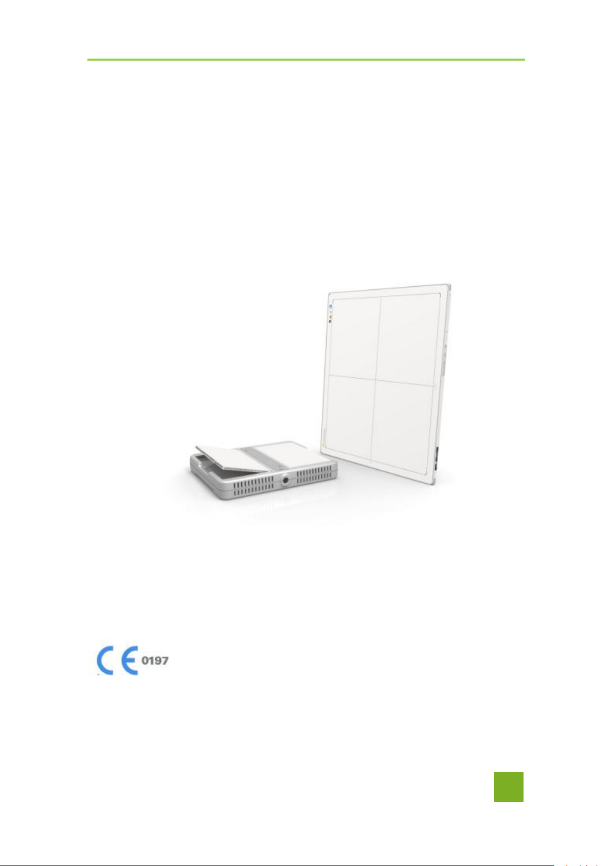
Wireless Digital Flat Panel Detector
E
Mars1417V
User Manual
To Customer
Document Version: A1
Document ID: 085-201-02
Release Date: 2019-08-22
Before operating, please read this user manual and pay attention to all safety precautions.
Please ensure that this user's manual is properly maintained so that it can be accessed at any time
(reserve).
Please use it correctly on the basis of full understanding of the content.
iRay Technology Co. Ltd.………………………………………………………………………………………………………………………………….………..
1

Mars1417V Digital Flat Panel Detector User Manual
Congratulations on your purchase of iRay Mars1417V (configuration: Mars1417V3)
Digital Flat Panel. At iRay, we strive to not only make the world-class products that
Service Office
Tel: +86 21 50720560
Fax: +86 21 50720561
E-mail: service@iraygroup.com
Location: Rm. NO.33 Xinggang Road, Taicang Port Economic and
Technological Development Zone, Jiangsu, China, PC: 215434
deliver the best value to our users but also offer the highest quality of service and customer care. Please
take time to read user manual to utilize the product effectively. We hope you enjoy the experience with
Mars1417V (configuration: Mars1417V3).
If you have any questions or suggestions, please feel free to contact us.
Notes on usage and management of the equipment
1. Read all of the instructions in user manual before operation. Give particular attention
to all safety precautions.
2. Only a physician or a legally certified operator could use the product.
3. The product should be maintained in a safe and operable condition by maintenance
personnel.
4. Use computers and image display monitors complying with IEC 60601-1 or IEC
60950-1. For details, consult our sales representative or local iRay dealer.
5. Use dedicated cables. Do not use any cables other than those supplied with the
product.
6. Request your sales representative or local iRay dealer to install the product
2
..................................................................................................................................................iRay Technology Co. Ltd.

Caring for your environment
This symbol indicates that this product is not to be disposed of with your residential or
commercial waste
Recycling iRay Equipment
Please do not dispose of this product with your residential or commercial waste. Improper
handling of this type of waste could have a negative impact on health and on environment.
Some countries or regions, such as the European Union, have set up systems to collect and
recycle electrical or electronic waste. Contact your local authorities for information about
dropping off waste product for recycling. If collection systems are not available, call iRay
Customer Service for assistance.
Disclaimer
1. iRay shall not be liable to the purchaser of this product or third parties for any
damage, loss, or injury incurred by purchaser or third parties as a result of fire,
To Customer
Copyright
earthquake, any accident, misuse or abuse of the product.
2. iRay shall not be liable to any damage, loss, or injury arising from unauthorized
modifications, repairs, or alterations to the product or failure to strictly comply with
iRay’s operating and maintenance instructions.
3. iRay shall not be liable for any damage or loss arising from the use of any options or
consumable products other than those dedicated as Original products by iRay
Technology.
4. It is the responsibilities of user or physician to maintain the privacy of image data
and provid medical care services. iRay shall not be responsible for the legality of
image processing , reading and storage nor it shall be responsible for loss of image
data for any reason.
5. Information regarding specification, compositions, and appearance of this product is
subject to change without prior notice.
1. All rights reserved
2. No part of this publication may be reproduced in any form or by any means without
the written permission of iRay. The information contained herein is designed only
for use with iRay Mars1417V.
Trademarks
The iRay name and iRay logo are registered trademarks of Shanghai iRay Technology Ltd.
iRay Technology Co. Ltd.……………………………………………………………………………………………………………………………….………..
3
Mars1417V Digital Flat Panel Detector User Manual
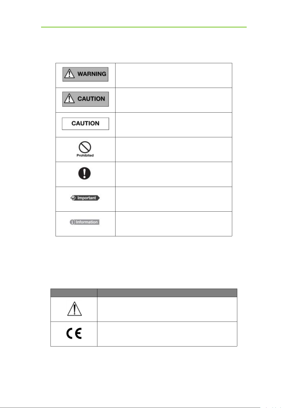
This symbol is used to identify conditions under which
improper use of the product may cause death or serious
personal injury.
This notice is used to identify conditions under which
improper use of the product may cause minor personal
injury.
This notice is used to identify conditions under which
improper use of the product may cause property damage.
This is used to indicate a prohibited operation.
This is used to indicate an action that must be performed.
This is used to indicate important operations and
restrictions.
This is used to indicate operations for reference and
complementary information.
ICON
MEANING
Caution: please refer to the instructions in user manual.
This symbol indicates that the product has passed CE certification
and followed by CE number.
Symbols and Conventions
The following symbols and conventions are used in user manual.
Labels and markings on the equipment
The contents of the labels and markings on Mars1417V (configuration: Mars1417V3) product are
indicated below:
4
..................................................................................................................................................iRay Technology Co. Ltd.
To Customer
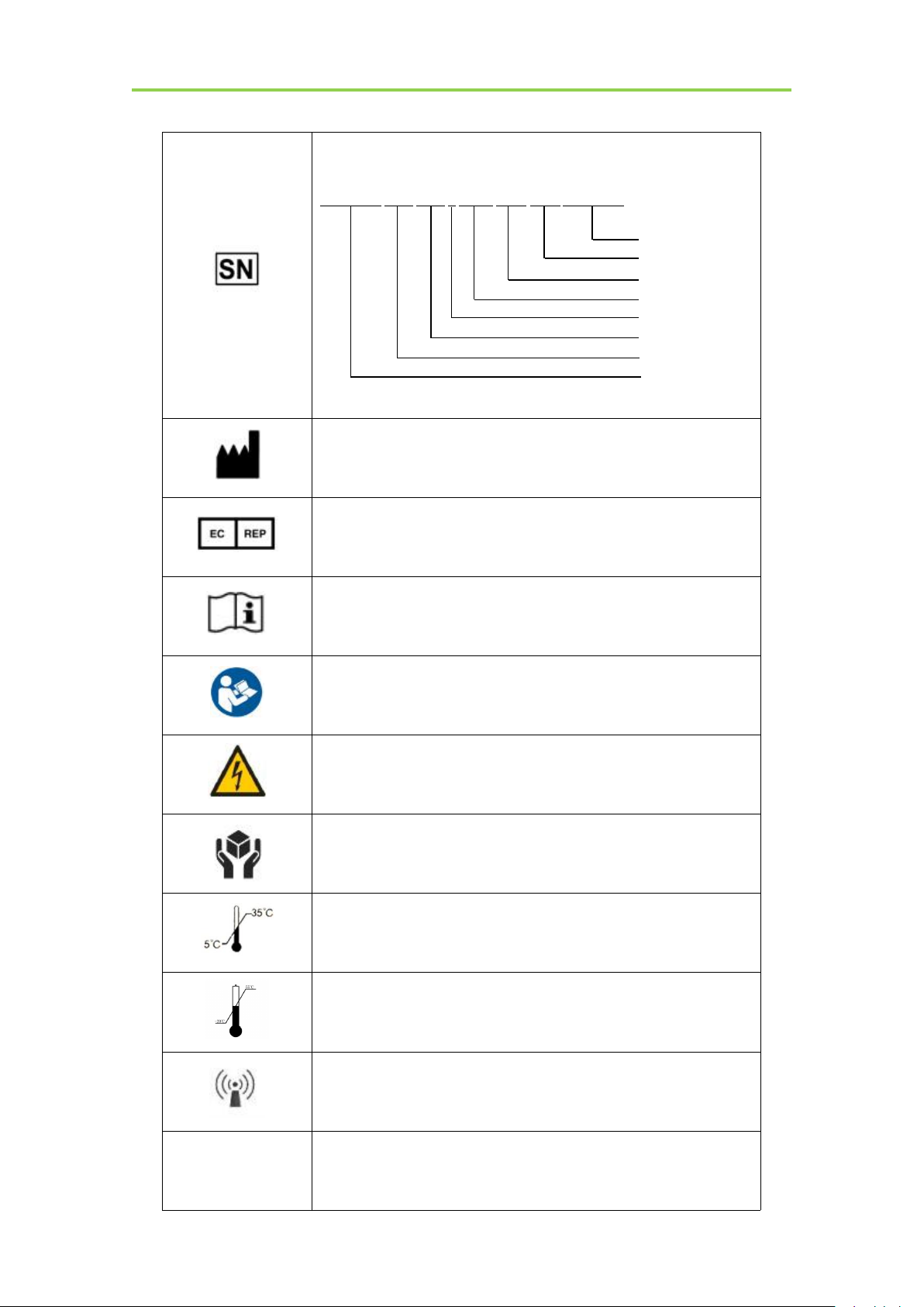
This symbol is used to identify the manufacture series number which
is after, below or adjacent to the symbol. The series number of iRay
products is usually made of nineteen digits as shown below:
A1A2A3A4 B1B2 C1C2 L M1M2 D1D2 Y1Y2 X1X2X3X4
Numerical Order
Year
Date
Month
Production site
Version
Derived classes
Product Code
This symbol indicates the name and address of manufacturer.
This symbol indicates the name and address of iRay authorized
representative in the European region.
This symbol is used to indicate consultation of the user guide for
general information.
Safety Signs: please refer to user manual for safety instructions
Safety Signs: Dangerous Voltage
Handled with care
This symbol indicates operational temperature limits.
This symbol indicates storage temperature limits.
This symbol indicates the product radiates wireless signal.
FCC
This symbol indicates the product has passed FCC certification.
iRay Technology Co. Ltd.……………………………………………………………………………………………………………………………….………..
5
Mars1417V Digital Flat Panel Detector User Manual
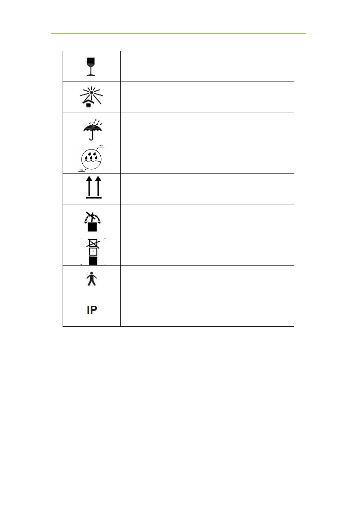
Package symbol, fragile.
Package symbol, keep away from sunlight.
Package symbol, keep dry.
This symbol indicates the humidity limits.
Keep the product up right
Do not roll the transportation package.
This symbol indicates stacking limit number.
Type-B applied part
IPX1 for working surface only
6
..................................................................................................................................................iRay Technology Co. Ltd.

Mars1417V Digital Flat Panel Detector User Manual
Contents
1. SAFETY
1.1. Safety precautions
1.2. Notes for Using
2. GENERAL DESCRIPTION
2.1. Scope
2.2. Model
2.3. Characteristic
2.4. Intended use/ essential performance/ application specification
2.4.1. Intended use.............................................................................................................................21
2.5. Essential performance
....................................................................................................................
..........................................................................................................................
................................................................................................................................
...........................................................................................
.................................................................................................................................................
..................................................................................................................................................
...................................................................................................................................
.......................................
..................................................................................................................
12
12
17
20
20
20
21
21
21
2.5.1. Application specification............................................................................................................21
2.6. The relative position between patient and detector
2.7. Product Components
2.8. Components Description
2.8.1. Detector......................................................................................................................................24
2.8.2. Battery........................................................................................................................................ 25
2.8.3. Battery Charger......................................................................................................................... 25
2.9. Product Specification
2.9.1. Detector......................................................................................................................................27
2.9.2. Battery........................................................................................................................................ 28
2.9.3. Battery Charger......................................................................................................................... 29
2.9.4. Power supply.............................................................................................................................. 29
2.9.5. AP Router...................................................................................................................................30
.....................................................................................................................
..............................................................................................................
....................................................................................................................
..............................................................
22
22
24
27
2.9.6. Wireless Communication........................................................................................................... 30
2.9.7. Recommended Application Condition........................................................................................30
2.9.8. Mechanical Outlines.................................................................................................................. 31
7
..................................................................................................................................................iRay Technology Co. Ltd.

Mars1417V Digital Flat Panel Detector User Manual
2.9.9. Use Environment........................................................................................................................31
2.10. IT network
2.10.1. Purpose for IT-network.............................................................................................................. 31
2.10.2. Required characteristics............................................................................................................ 32
2.10.3. Required configuration.............................................................................................................. 32
2.10.4. Technical specifications............................................................................................................. 32
2.10.5. Intended information flow.......................................................................................................... 32
2.10.6. Hazardous situations resulting from failure of the IT-network................................................. 32
2.10.7. Warning......................................................................................................................................33
2.10.8. Changes to the IT-network include............................................................................................ 33
3. INSTALLATION
3.1. Panel Installation
3.1.1. Attach Battery Pack....................................................................................................................35
3.1.2. Attach DC Power....................................................................................................................... 35
3.1.3. Booting Up................................................................................................................................. 36
....................................................................................................................................
..........................................................................................................
............................................................................................................................
31
35
35
3.1.4. Button function........................................................................................................................... 38
3.2. Battery Charger Installation
3.3. Software Installation
3.4. Panel Infrastructure
3.4.1. Wireless Client Mode................................................................................................................. 40
3.4.2. Wireless AP Mode...................................................................................................................... 44
4. OPERATION
4.1. Main Operation
4.1.1. Software Mode........................................................................................................................... 50
4.1.2. Inner2 Mode............................................................................................................................... 52
4.1.3. Freesync Mode...........................................................................................................................54
4.2. Connection Build
...............................................................................................................
......................................................................................................................
........................................................................................................................
................................................................................................................................
............................................................................................................................
.........................................................................................................
38
39
39
50
50
55
4.3. Panel Configuration
4.4. Correction and Calibration Template Generation
8
..................................................................................................................................................iRay Technology Co. Ltd.
.......................................................................................................................
..................................................................
56
57

Contents
4.4.1. Pre-offset Template Generation................................................................................................. 57
4.4.2. Gain Calibration Template Generation..................................................................................... 59
4.4.3. Defect Correction Template Generation....................................................................................60
4.5. Image Check and upload
4.5.1. Local Image Check.....................................................................................................................62
4.5.2. Panel Image Upload.................................................................................................................. 63
4.6. Defect Template Check and Modification
4.6.1. Defect Template Check.............................................................................................................. 64
4.6.2. Defect Template Modification.................................................................................................... 65
4.7. Correction and Calibration Management
4.7.1. Correction and Calibration template synchronization.............................................................. 66
4.7.2. Correction and Calibration management.................................................................................. 67
4.8. Firmware Update
4.8.1. MCU Update.............................................................................................................................. 68
4.8.2. FPGA Update............................................................................................................................. 71
4.8.3. ARM Update............................................................................................................................... 73
4.8.4. ALL FIRMWARE Update........................................................................................................... 75
.............................................................................................................................
..............................................................................................................
................................................................................
.................................................................................
62
63
66
68
4.9. Short cut
4.10. Software
4.10.1. Main GUI................................................................................................................................... 76
4.10.2. Message Box...............................................................................................................................77
4.10.3. Configuration GUI..................................................................................................................... 78
4.11. List of the HAZARDOUS SITUATIONS resulting from a failure of the IT-
NETWORK
5. REGULATORY INFORMATION
5.1. Medical equipment safety standards
5.2. The compliance for each EMISSIONS and IMMUNITY standard or test specified by
IEC60601-1-2 standard
5.3. Radio Frequency Compliance Information
............................................................................................................................................
.......................................................................................................................................
.........................................................................................................................................
...................................................................................
........................................................................................
..................................................................................................................
..............................................................................
75
76
81
83
83
84
87
iRay Technology Co. Ltd.……………………………………………………………………………………………………………………………….………..
9

Mars1417V Digital Flat Panel Detector User Manual
5.3.1. FCC Compliance........................................................................................................................87
5.4. Battery Safety Standards
6. TROUBLE SHOOTING
7. SERVICE INFORMATION
7.1. Product Lifetime
7.2. Regular Inspection and Maintenance
7.3. Repair
7.4. Replacement Parts Support
APPENDIX A INFORMATION OF MANUFACTURES
APPENDIX B INFORMATION OF MEDICAL DEVICE DIRECTIVE EUROPEAN
REPRESENTATIVE
.................................................................................................................................................
..............................................................................................................................
.....................................................................................................
..............................................................................................................
.................................................................................................
...........................................................................................
........................................................................................
.........................................................................................................
...........................................................
88
90
92
92
92
92
92
94
95
10
..................................................................................................................................................iRay Technology Co.
Ltd.

Mars1417V Digital Flat Panel Detector User Manual
1. SAFETY
1.1. Safety precautions
1.2. Notes for Using
......................................................................................................................
................................................................................................................................
..........................................................................................................................
12
12
17
11
................................................................................................................................................iRay Technology Co. Ltd.
1. Safety
WARNING
Installation and
environment of
use
Do not use or store the product near flammable
chemicals such as alcohol, thinner, benzene, etc.
If chemicals are spilled or evaporated, it may result in fire
or electric shock through contact with electric parts inside
the product. Also, some disinfectants are flammable. Be
sure to take care when using them.
Do not connect the equipment with anything other than
specified.
Doing so may result in fire or electric shock.
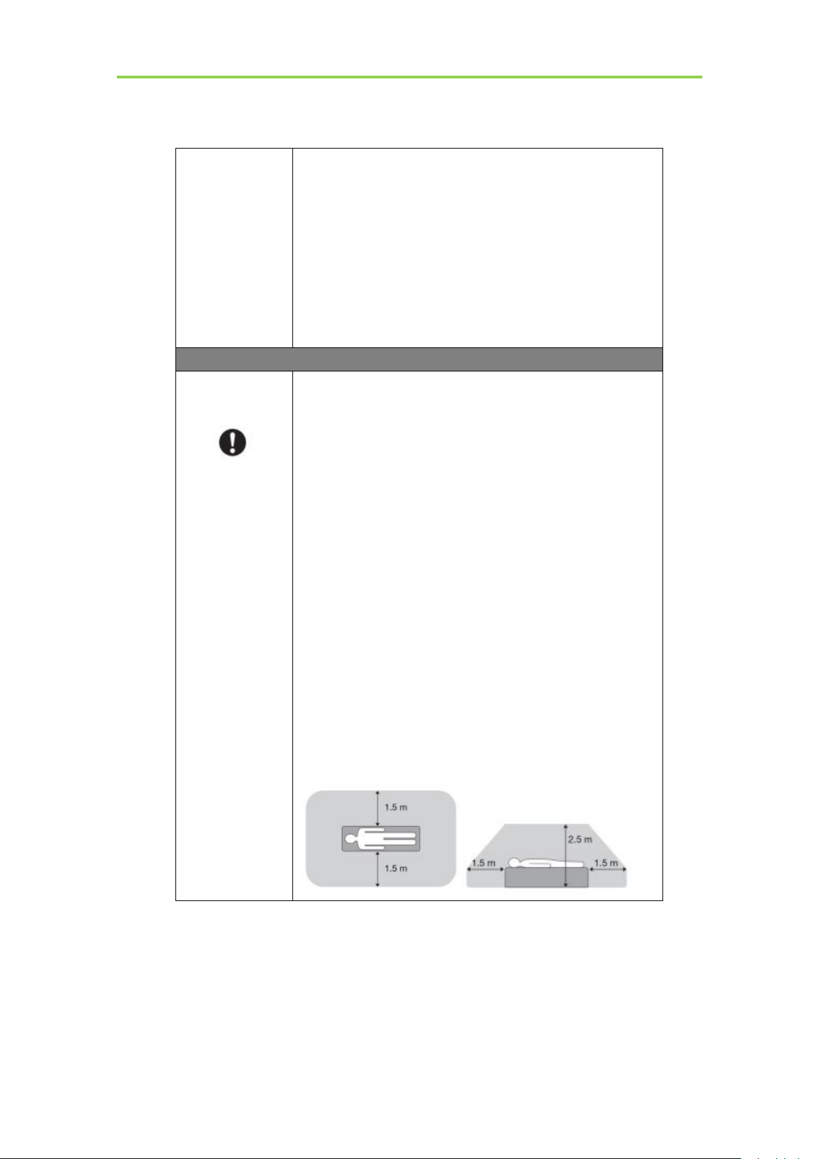
All patients with active implantable medical devices
should be kept away from the product.
Power supply
Do not operate the product with power supply other
than the one indicated on the rating label.
Otherwise, it may result in fire or electric shock.
Do not handle the product with wet hands.
You may experience electric shock that could result in
death or serious injury.
Do not place heavy object on cables and cords. Do not
pull, bend, bundle, or step on them to prevent their
sheath from being damaged, and do not alter them
neither.
Doing so may damage the cords which could result in fire
or electric shock.
Do not supply power to more than one piece of product
with the same AC outlet.
Doing so may result in fire or electric shock.
Do not turn on system power when condensation has
formed on the equipment.
Doing so may result in fire or electric shock.
Do not connect multiple portable socket-outlets or
extension cords to the system.
Doing so may result in fire or electric shock.
To avoid the risk of electric shock, this product must
only be connected to power supply with protective
earth.
Not doing so may result in fire or electric shock.
Do not connect the adapter cord when connect the
panel to patient.
1.1. Safety precautions
Follow these safeguards and properly use the product to prevent injury and damage to it.
Safety
iRay Technology Co. Ltd.………………………………………………………………………………………………….…………………………….………..
12
Safety
Securely plug the power cord into the AC outlet.
If contact failure occurs, or if metal objects come into
contact with exposed metal prongs of the plug, fire or
electric shock may result.
Be sure to turn off the power before connecting or
disconnecting the cords.
Otherwise, you may get an electric shock that could result
in death or serious injury.
Be sure to hold the plug or connector to disconnect the
cord.
If you pull the cord, the core wire may be damaged,
resulting in fire or electric shock.
WARNING
Handling
Never disassemble or modify the product. No
modification is allowed.
Doing so may result in fire or electric shock. Also, since
the product incorporates parts that may cause electric
shock as well as other hazardous parts, touching them may
cause death or serious injury.
Do not place anything on top of the product.
The object may fall and cause an injury. Also, if metal
objects such as needles or clips fall into the product, or if
liquid is spilled, it may result in fire or electric shock.
Do not hit or drop the product.
The product may be damaged if it receives a strong jolt,
which may result in fire or electric shock if it is used
without being repaired.
Do not put the product and pointed objects together.
The product may be damaged. If so, it should be used in
bucky.
Have the patient take a fixed posture and do not let the
patient touch parts unnecessarily.
If the patient touches connectors or switches, it may result
in electric shock or malfunction.
When a problem
occurs
Should any of the following occurs, immediately unplug
the power cord of adaptor or battery, and contact your
sales representative or local iRay dealer:
When there is smoke, an odd smell or abnormal sound.
When liquid has been spilled into the equipment or a metal
object has entered through an opening.
When the product has been dropped and damaged.
Maintenance and
inspection
Please turn off power of the product and unplug power
cord of adapter before cleaning.
Never use alcohol, ether and other flammable cleaning
agent for safety. Never use methanol, benzene and acid
because they would corrode the equipment.
Don’t dip the product into liquid.
Please make sure that surface & plugs are dry before
turning on.
Otherwise, it may result in fire or electric shock.
iRay Technology Co. Ltd.……………………………………………………………………………………………………………………………….………..
13
Mars1417V Digital Flat Panel Detector User Manual
Clean the plug of the power cord periodically by
unplugging it from the AC outlet and removing dust or
dirt from the plug, its periphery and AC outlet with a
dry cloth.
If the cord is kept plugged in for a long time in a dusty,
humid or sooty place, dust around the plug will attract
moisture; this could cause insulation failure that may result
in a fire.
For safety reasons, be sure to turn off the power when
performing inspections indicated in this manual.
Otherwise, electric shocks may occur.
CAUTION
Installation and
environment of
use
Do not install the product in any of the locations listed
below. Doing so may result in failure, malfunction,
falling, fire or injury.
Close to facilities where water is used
Where it will be exposed to direct sunlight
Close to the air outlet of an air-conditioner or ventilation
equipment
Close to heat source such as a heater
Where the power supply is unstable
In a dusty environment
In a saline or sulfurous environment
Where temperature or humidity is high
Where there is freezing or condensation
In areas prone to vibration
On an incline or in an unstable area
Take care that cables do not become tangled during
use. Also, be careful not to get your feet caught by
cable.
Otherwise, it may cause a malfunction of the product or
injury of the user due to tripping over the cable.
Non-medical equipment such as battery charger, access
point and infrared register tools cannot be used in
patient’s vicinity.
14
................................................................................................................................................iRay Technology Co. Ltd.
Safety
Power supply
Always connect three-core power cord plug to a
grounded AC power outlet.
To make it easy to disconnect the plug at any time,
avoid putting any obstacles near the outlet. Otherwise,
it may not be possible to disconnect the plug in an
emergency.
Be sure to ground the product to an indoor grounded
connector. Also, be sure to connect all the grounds of
system to common ground.
Do not use any power source other than the one
provided with the product.
Otherwise, fire or electric shock may be caused due to
leakage.
Handling
Do not spill liquid or chemicals onto the equipment. In
case the patient is injured, it is not allowed to contact
with blood or other body fluids.
Doing so may result in fire or electric shock.
In such a situation, protect the equipment with a disposable
cover as necessary.
Turn OFF the power and pull out the plug to each
piece of equipment for safety when not used.
CAUTION
Handling
Handle the product carefully.
Do not submerge the product in water.
Only working surface meets IPX1
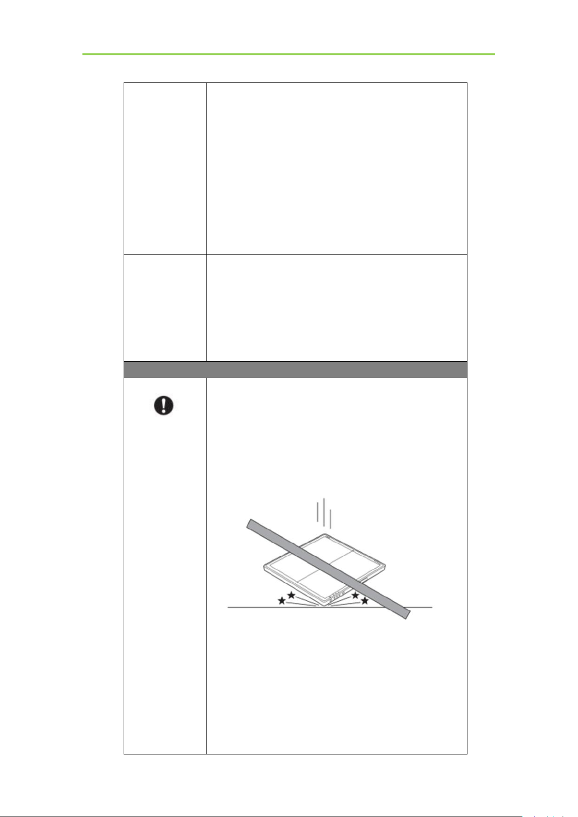
The internal image sensor may be damaged if
something hits against it or it is dropped. If the product
is dropped, the drop sensor inside would record and
the product would not be warranted by iRay.
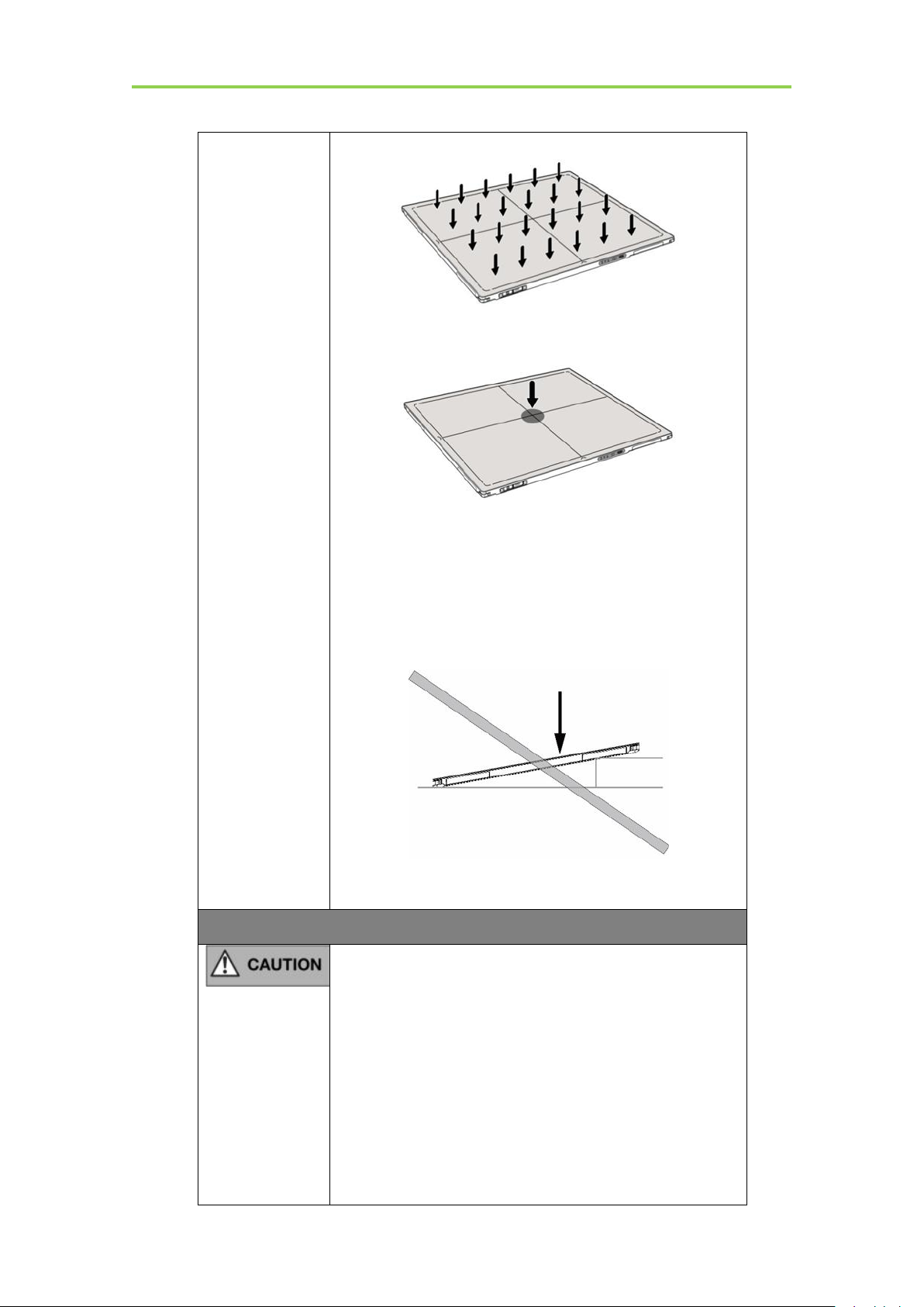
Do not place excessive weight on the panel.
Otherwise, the internal image sensor may be damaged and
image may be incorrect.
Patients stand on the product temporarily, and the intended
weight can be 135kg.
Based on the internal TFT character, cannot load the
dynamic forces due to loading from persons
<Load Limit>
iRay Technology Co. Ltd.……………………………………………………………………………………………………………………………….………..
15
Mars1417V Digital Flat Panel Detector User Manual
Uniform load:150 kg over the whole area of the surface.
Local load:100 kg on an area 4 cm diameter.
Be sure to use the product on flat surface so it would
not bend. Otherwise, the internal image sensor may be
damaged. Be sure to securely hold the product while
using it in upright positions. Otherwise, the product
may fall over, resulting in injury to user or patient, or
may flip over, resulting in damage to the inner device.
Keep the same load on the product when acquiring image.
The image will be incorrect.
CAUTION
Do not close to fire, do not use in high temperature
Do not invert positive and negative pole
Do not contact with metal in case of short circuit
Do not insert sharp objects into battery
Do not beat battery
Do not stand on battery
Do not use battery out of rules
Do not dispose of battery or change inner structure
Do not submerge battery in water, please keep dry in
storage and do not contact with water in use
Please charge battery with charger following GB
16
................................................................................................................................................iRay Technology Co. Ltd.

9706.1 Standards provided by us
Do not mix battery with ones not provided by our
company
Do not charge battery with broken charger.
Substitution of battery inside main unit must be
carried out by qualified people
Do not touch output connector for adaptor
Do not remove the battery when the panel is powered
on only with the battery.
1.2. Notes for Using
When using the product, take the following precautions. Otherwise, problems may
occur and the product may not function correctly.
Before exposure
Safety
Be sure to check the product daily and confirm it work properly.
Sudden heating of the room in cold areas will cause condensation on the
product. In this case, wait until the condensation evaporates before performing
an exposure. If it is used when condensation is formed, problems may occur in
the quality of captured images. When an air-conditioner is used, be sure to
raise/lower the temperature gradually to prevent condensation.
The product should be warmed up for 15 minutes before exposure or updating
the gain map and defect map.
Make sure exposure rate is over 900nGy/s @70KV.
Make sure wave form of the energy going to the X ray tube is square not pulse.
Be cautious with circumstance that someone has radio isotope recently injected
into them, it may cause that panel transmit image without x ray.
During exposure
Do not move Power Cable, or it may cause image noise or artifacts, even
incorrect images.
Do not use the product near the equipment generating a strong magnetic field.
Otherwise, it may cause image noise, artifacts or even incorrect images.
iRay Technology Co. Ltd.……………………………………………………………………………………………………………………………….………..
After usage
It’s strongly recommended to remove battery from panel if panel is not used
more than 5 days. If battery stores for a long time, it should be charged (30% to
50%) every 3 month or charged (50% to 70%) every 6 month.
17

Mars1417V Digital Flat Panel Detector User Manual
Contact with the patients parts cleaning, disinfection and sterilization
After every examination, wipe the patient contact surfaces with nonflammable
disinfectants to prevent the risk of infection, such as benzalkonium chloride,
benzalkonium bromide. For details on how to sterilize, consult a specialist.
Do not spray the product directly with disinfectants or detergents.
Wipe it with a cloth slightly damped with a neutral detergent. Do not use
solvents such as benzene and acid. Doing so may damage the surface of the
product.
It’s recommended to use a waterproof non-woven cover as the isolated layer
between product and the blooding patient.
Applied part
The front and back of detector is application part.
18
................................................................................................................................................iRay Technology Co. Ltd.

Mars1417V Digital Flat Panel Detector User Manual
2.GENERAL DESCRIPTION
2.1. Scope
2.2. Model
2.3. Characteristic
2.4. Intended use/ essential performance/ application specification
2.5. Essential performance
2.6. The relative position between patient and detector
2.7. Product Components
2.8. Components Description
2.9. Product Specification
............................................................................................................................................
.............................................................................................................................................
................................................................................................
.............................................................................................................................
.............................................................................................................
.........................................................
...............................................................................................................
.........................................................................................................
...............................................................................................................
..................................
20
20
20
21
21
21
22
22
24
27
2.10. IT network
....................................................................................................................................
31
19
................................................................................................................................................iRay Technology Co. Ltd.
Mars1417V Digital Flat Panel Detector User Manual
2. General Description
Mars1417V (configuration: Mars1417V3, hereinafter referred as Mars1417V) is a cassettesize wireless X ray flat panel detector based on amorphous silicon thin-film transistor
technologies. It is developed to provide the highest quality of radiographic image, which
contains an active matrix of 2304×2800 with 150um pixel pitch. The greatest feature is
Mars1417V supports wireless communication between panel and Workstation. Mars1417V’s
power supply includes battery. Mars1417V can be used as a real portable panel.
2.1. Scope
This manual contains information about the Mars1417V. Information in the manual, including
the illustrations, is based on prototype. If your configuration does not have any of these items,
information about these items does not apply to your panel.
2.2. Model
Mars □ □ □
TSI- CsI Model
Product Application: Cassette size portable detector
Product dimension: 1417, 14inch×17inch
Product series: Wireless digital flat panel detector series
Product Type: Battery-KV---------Rechargeable lithium battery
Product Type: Charger-KV--------Battery charger
20
................................................................................................................................................iRay Technology Co. Ltd.

Installation
2.3. Characteristic
Wireless static flat panel detector used for general radiography.
Cassette-size
Sync-shot exposure trigger
CsI scintillation screen.
Easy to change the cable and update firmware.
Battery recycling
2.4. Intended use/ essential performance/ application specification
2.4.1. Intended use
Mars1417V Wireless Digital Flat Panel Detector is indicated for digital imaging solution
designed for providing general radiographic diagnosis of human anatomy. It is intended to
replace radiographic film/screen systems in all general-purpose diagnostic procedures. This
panel provides digital X ray imaging for diagnosis of disease, injury, or any applicable health
problem. The image is obtained as the result of X ray passing through the human body and
detected by detector.
iRay would provide hardware and software support for integration of system.
This panel is not intended for mammography and extra-oral X-ray applications which are
covered by IEC60601-2-63.
2.5. Essential performance
According to the Mars1417V series intended use and the result of risk management, getting
imaging and function of data transmission is defined as essential performance.
Getting qualified dark image proves that essential performance does not influence intended
use. Method for getting dark image in detail refers to section “install” and “operation”.
2.5.1. Application specification
PATIENT population:
Age: except for children
Weight: not relevant
Health: not relevant
Nationality: multiple
Patient state: patient is not user
Gender: except for pregnant women
iRay Technology Co. Ltd.……………………………………………………………………………………….……………………………………….………..
21
Mars1417V Digital Flat Panel Detector User Manual
Item
Description
Mars1417V Detector
1pcs
Main Unit
Intended OPERATOR:
All of use, maintenance and operation steps should be carried out by the operator who has
accepted the professional training offered by the company's customer service staff.
Life-time:
Life-time: 7 years without frequency limit
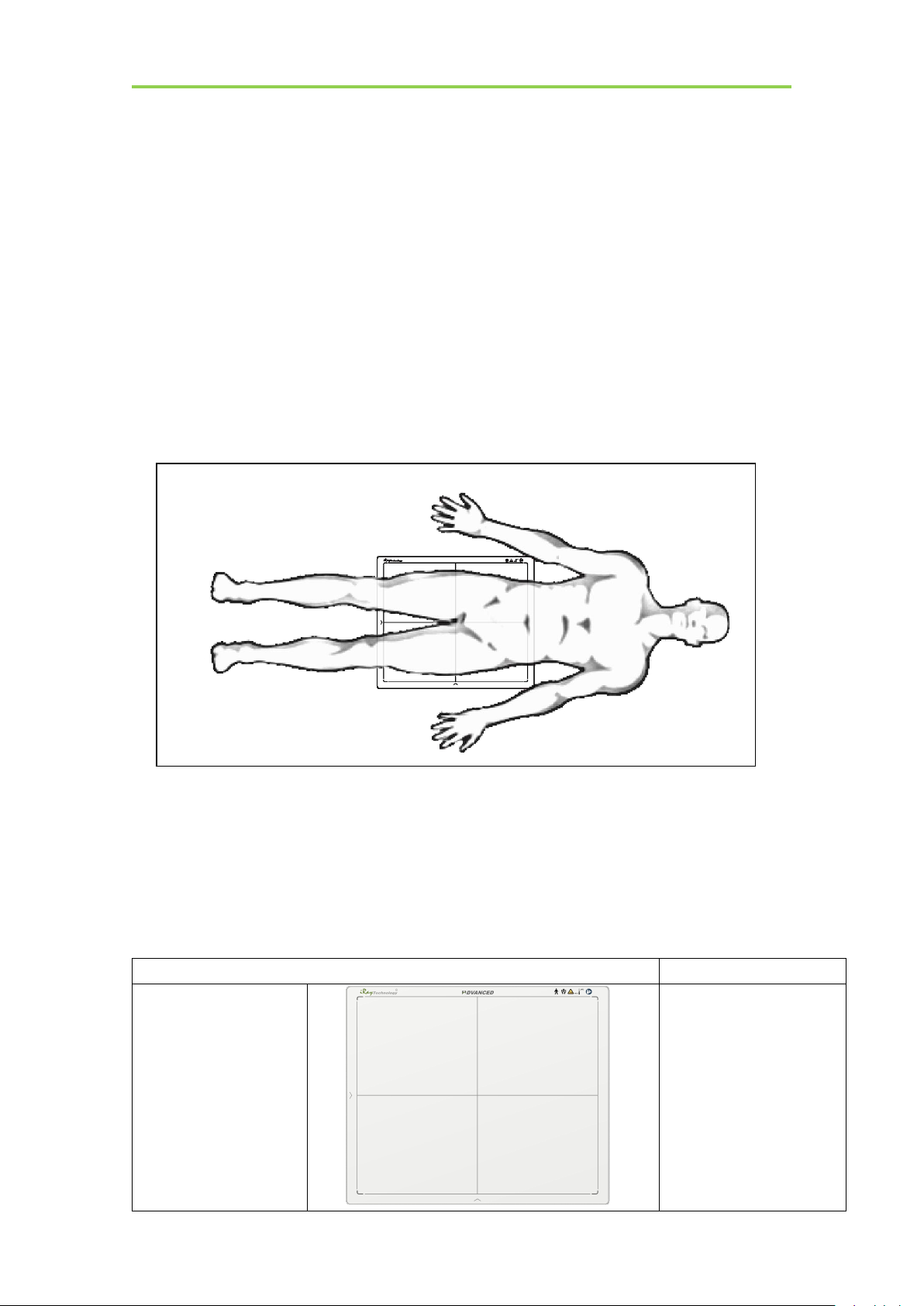
2.6. The relative position between patient and detector
Because of the crosstalk effect of Amorphous silicon flat-panel detector, Pay attention to the
relative position of patient and detector, the recommended position as shown below,
Otherwise, the image is prone to abnormal light lines.
2.7. Product Components
Mars1417V comes with both DC power supply and battery package. Once powered
on, it would build a connection with Workstation through Ethernet cable (only for
service) or Wireless connection.
22
................................................................................................................................................iRay Technology Co. Ltd.

Installation
Medical Adapter
1 pcs
DC 24V
Battery
2 pcs
Battery pack
Ethernet Cable
(Only for service)
1pcs
3.5 m
Gigabit Ethernet Cable
1pcs
3 m
AC Power Cable
1 pcs
DC Power Cable
1 pcs
3.5 m
iRay Technology Co. Ltd.……………………………………………………………………………………….……………………………………….………..
23
Mars1417V Digital Flat Panel Detector User Manual
Battery Charger
1pcs
CD-Rom
1pcs
Gain correction data
Defect correction map
SDK
Manual
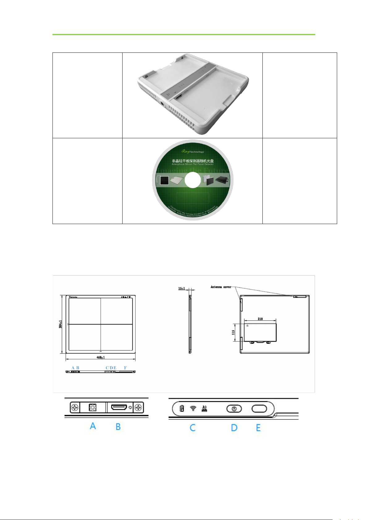
2.8. Components Description
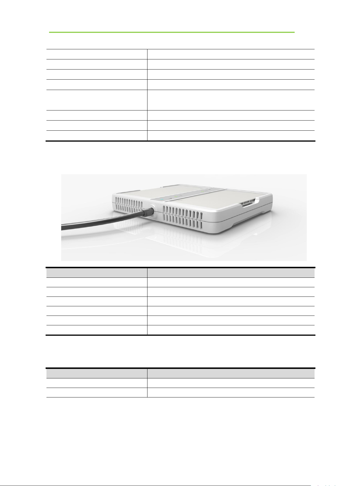
2.8.1. Detector
External Signals Input Control Panel
24
................................................................................................................................................iRay Technology Co. Ltd.
Item
Name
Description
A
DC Jack
24V DC input
B
Ethernet Port
Gigabit Ethernet port
C
Detector Indicator
Detector indicator of control panel
D
Power Button
Power button of control panel
E
reserved
/
F
Antenna
Antenna
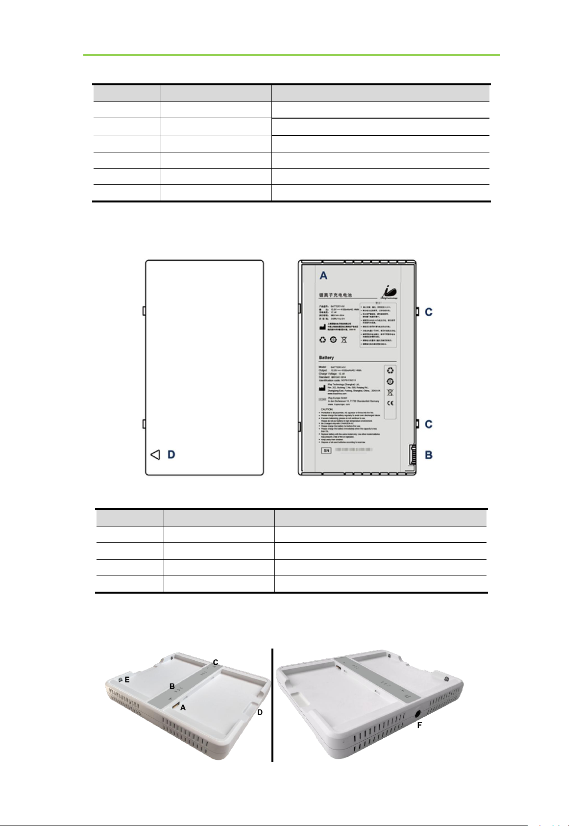
2.8.2. Battery
Item
Name
Description
A
Battery Label
/
B
Battery Interface
8 Pin Battery connector
C
Pilot Pin
/
D
Indicator
Installation direction indicator
Installation
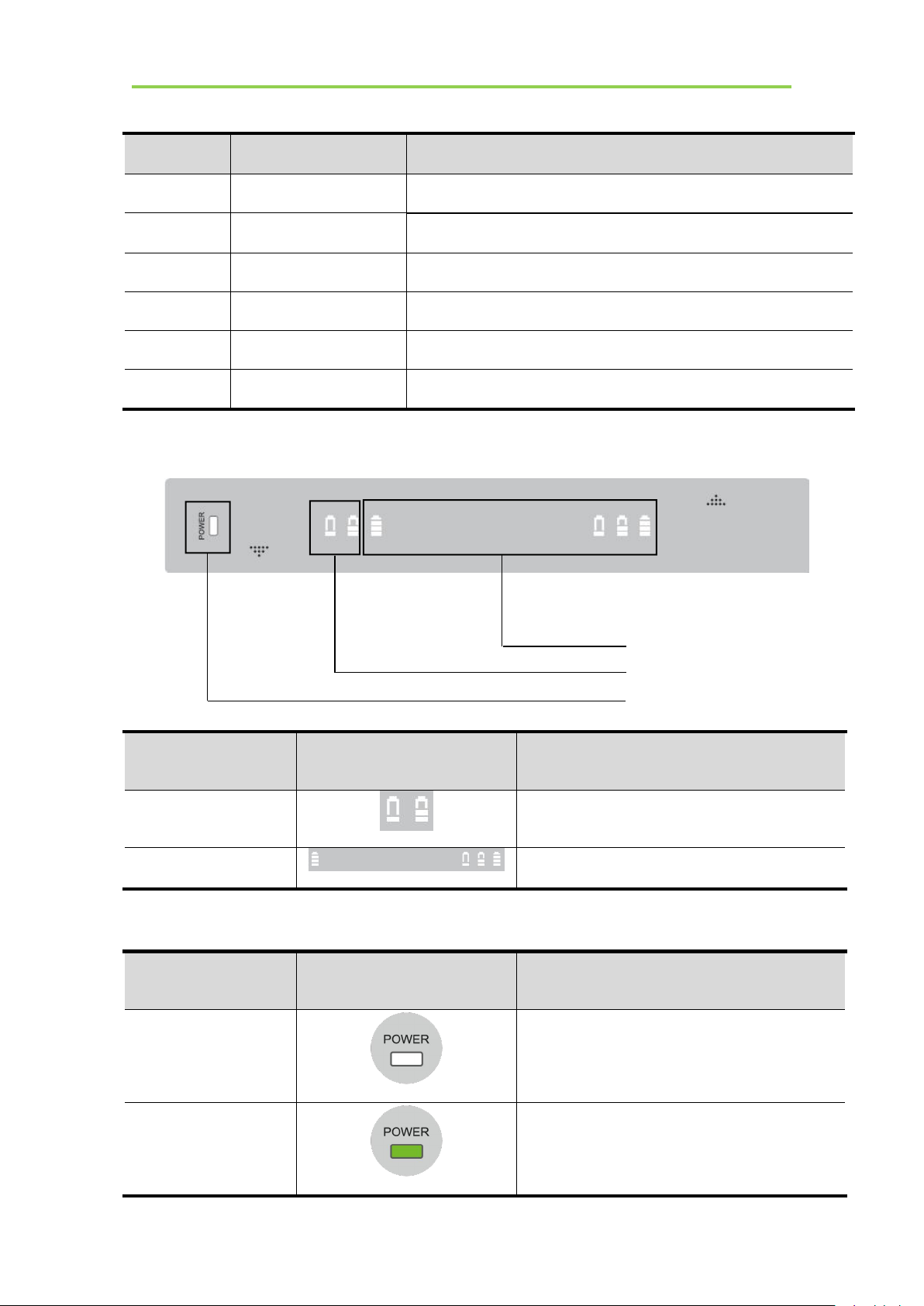
2.8.3. Battery Charger
iRay Technology Co. Ltd.……………………………………………………………………………………….……………………………………….………..
25
Mars1417V Digital Flat Panel Detector User Manual
Item
Name
Description
A
Battery Interface
8 Pin Battery connector
B
Capacity Indicator
The indicator definition is as follow
C
Power Indicator
The indicator definition is as follow
D
Hand Pull Position
/
E
The limit ball plug
/
F
DC Jack
24V DC input
Firmware versions
Lighting Status
Value range (BCD)
Major
00-11
Minor
0000-1111
Power Indicator
Lighting Status
Operating Status
OFF
No external DC adaptor input
GREEN
External DC adaptor input
Firmware major versions
Firmware minor versions
Power indicator
Firmware versions definition
Power indicator definition:
26
................................................................................................................................................iRay Technology Co. Ltd.
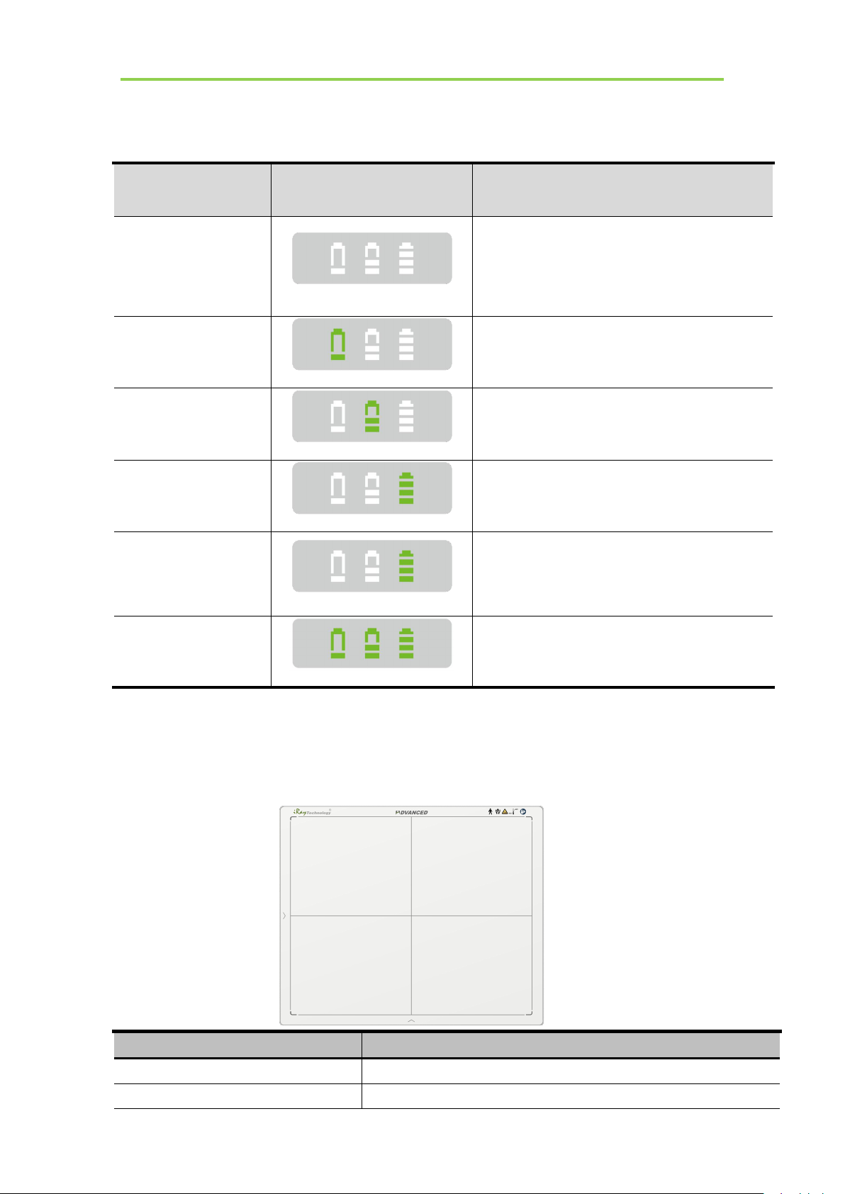
The battery charging capacity indicator definition:
X Group Indicator
Lighting Status
Operating Status
I, II and III grid off
No battery Insert
I grid blinking
II and III grid off
Battery Insert with capacity ≤30%,charging
II grid blinking
I and III grid off
Battery Insert with capacity >30% and ≤60%,
charging
III grid blinking
I and II grid off
Battery Insert with capacity >60% and ≤95%,
charging
I and II grid off
III grid on
Battery Insert with capacity >95% and
charging, when capacity = 100%, charging
stops
I, II and III blinking
Battery enter into 2nd level protection,
automatic unlock with safety condition
Item
Specification
Model
Mars1417V-TSI (CsI)
Image Sensor
a-Si (Amorphous Silicon) TFT
Installation
2.9. Product Specification
2.9.1. Detector
iRay Technology Co. Ltd.……………………………………………………………………………………….……………………………………….………..
27
Mars1417V Digital Flat Panel Detector User Manual
Pixel Size
150 μm
Active Array
2304 x 2800
Active Area (H x V)
345.6mm x 420mm
Gray scales
16bit
Spatial Resolution
3.3 Lp/mm
Image Acquisition Time (Wireless)
Both AP mode and Client mode
Preview Acquisition Time: 3 sec.
Processed Acquisition Time : 5 sec.
Cycle Time
Min. 8s
Power Consumption
Max. 18W
Dimension (L × W × H)
460 x 384 x 15 mm
Weight (with one battery)
3.43 kg
Image Transfer
Wireless : IEEE802.11a/b/g/n/ac
Data Transmission Rate (Wireless)
802.11b: Max. 11Mbps
802.11a/g: Max. 54Mbps
802.11n: Max. 300Mbps (MIMO 2x2)
802.11ac: Max. 867Mbps(MIMO 2x2)
Item
Specifications
Model
Battery-KV
Rated Capacity
Typ. 4180mAh @ Discharge 0.2C
Nominal Voltage
10.8V
2.9.2. Battery
28
................................................................................................................................................iRay Technology Co. Ltd.
Charge Voltage
12.6±0.05V
Discharged End Voltage
9V
Charging Method
CC-CV
Operating Temperature
Charge 0℃-+60℃, Discharge-10℃-+60℃
Storage Temperature
≤3 month -20℃-+45℃
≤6 month -20℃-+35℃
Relative Humidity
5%~95%
Dimension (L × W × H)
210 x 115 x 7.5 mm
Weight
0.28kg
2.9.3. Battery Charger
Item
Specifications
Model
Charger-KV
Simultaneous Charging
2 battery packs
Full charging time
2.5 hours
Rated power supply
24V(DC)
Dimension (L × W × H)
300 x 263 x 42 mm
Weight
1.26 kg
Item
Specifications
DC Power
24V(DC), 0.75A
Battery Package
10.8V(DC),1.6A
Installation
2.9.4. Power supply
Mars1417V supports both DC Power and Battery package input.
The product must be used with the approved adaptor whose CB certificate number is SG PSB-MD-
00191.
iRay Technology Co. Ltd.……………………………………………………………………………………….……………………………………….………..
29

Mars1417V Digital Flat Panel Detector User Manual
Item
Specifications
Wireless Standard
IEEE 802.11 a/b/g/n/ac
Frequency Range
2.412 ~ 2.4835 GHz and 5.15 ~ 5.85 GHz
Wireless Data Rate
802.11b: Max. 11Mbps
802.11a/g: Max. 54Mbps
802.11n: Max. 300Mbps (MIMO 2x2)
802.11ac: Max. 867Mbps(MIMO 2x2)
Item
Description
Wireless Standard
IEEE 802.11a/b/g/n/ac
Frequency Range
2.412~2.472GHz: ch1~ch13
5.18~5.24GHz: ch36~ch48
5.745~5.85GHz: ch149~ch165
Data Transmission Rate
802.11b: Max. 11Mbps
802.11a/g: Max. 54Mbps
802.11n: Max. 300Mbps (MIMO 2x2)
802.11ac: Max. 867Mbps(MIMO 2x2)
Modulation
802.11b:
CCK, DQPSK, DBPSK
802.11a/g/n:
64 QAM, 16 QAM, QPSK, BPSK
802.11ac:
256 QAM, 64 QAM, 16 QAM, QPSK, BPSK
Transmission Power
Max.17dBm
Security
WPA, WPA-PSK, WPA2, WPA2-PSK, WEP 64bit & 128bit
Antenna
2 Dual Band inner antenna
Item
Description
Operating System
Windows 7 32/64bit
CPU
Intel Core i7 3.6G
Memory
4G DDR3
Hard Disk
640 G
LAN Card
Intel Pro EXP9301CT PRO
2.9.5. AP Router
Mars1417V do not include AP Router. Users can choose AP Router as they wish, however specification
below is a requirement.
2.9.6. Wireless Communication
2.9.7. Recommended Application Condition
30
................................................................................................................................................iRay Technology Co. Ltd.

2.9.8. Mechanical Outlines
Temperature
Temperature
change
Humidity
Atmospheric
Pressure
Pressure Change
Operating
5~35℃
<1k/min
10%~90% RH
700~1060hPa
<10kp/min
(1kp=1.0197E-5Pa)
Storage
-20~55℃
<1k/min
5%~95% RH
700~1060hPa
<10kp/min
(1kp=1.0197E-5Pa)
The Mars1417V serial detectors shall operate at an altitude specified not more than 3000m, the environment
is only for detector.
Installation
2.9.9. Use Environment
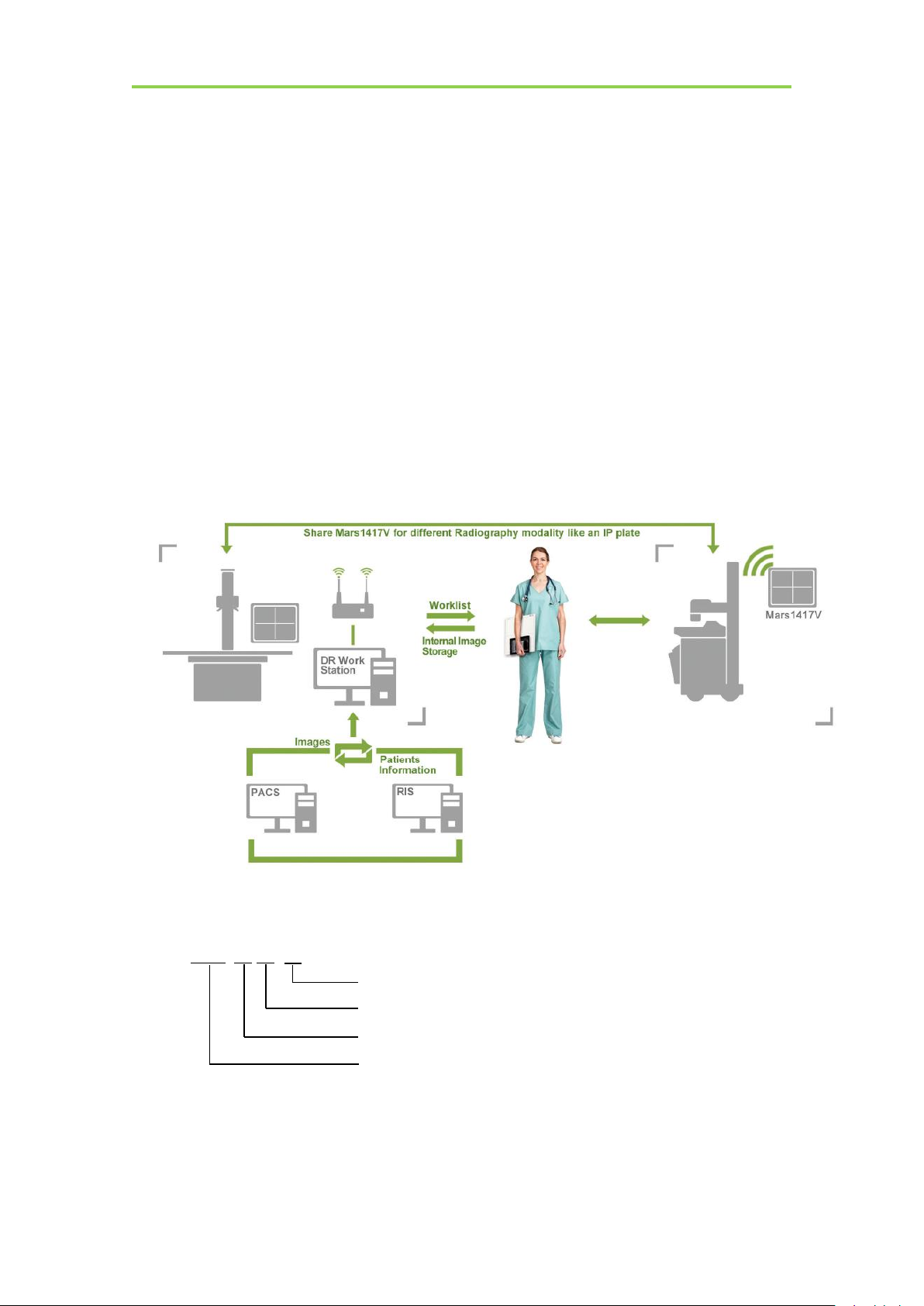
2.10. IT network
2.10.1. Purpose for IT-network
Transmission between the detector and the workstation is image data and command/status
communication.
iRay Technology Co. Ltd.……………………………………………………………………………………….……………………………………….………..
31

Mars1417V Digital Flat Panel Detector User Manual
Item
Description
Wireless Standard
IEEE 802.11a/b/g/n/ac
Frequency Range
2.412~2.472GHz: ch1~ch13
5.18~5.24GHz: ch36~ch48
5.745~5.85GHz: ch149~ch165
Data Transmission Rate
802.11b: Max. 11Mbps
802.11a/g: Max. 54Mbps
802.11n: Max. 300Mbps (MIMO 2x2)
802.11ac: Max. 867Mbps(MIMO 2x2)
Modulation
802.11b:
CCK, DQPSK, DBPSK
802.11a/g/n:
64 QAM, 16 QAM, QPSK, BPSK
802.11ac:
256 QAM, 64 QAM, 16 QAM, QPSK, BPSK
Security
WPA, WPA-PSK, WPA2, WPA2-PSK, WEP 64bit & 128bit
2.10.2. Required characteristics
Wireless communication follows IEEE 802.11a/b/g/n/ac protocol. It works on 2.4GHz and
5GHz.
It supports at least 2 routers.
2.10.3. Required configuration
The wireless card and the detector must work on the same IP segment such as 192.168.8.XXX
They must support IEEE 802.11a/b/g/n/ac.
2.10.4. Technical specifications
2.10.5. Intended information flow
The detector sends image data acquired to the workstation. The workstation sends users’
commands to the detector. Please refer to the operation manual of the Console for detail.
2.10.6. Hazardous situations resulting from failure of the IT-network
1. Failure of completing essential performance
2. Failure of finishing configuration of product
3. Operating system is not compatible
4. Change or update software failed
5. Compatibility of interface
6. Data transfer protocol error
32
7. Inconsistency of interface or format leads to data distortion;
8. Data output failed;
................................................................................................................................................iRay Technology Co. Ltd.

2.10.7. Warning
Connection of the main unit to an IT-network that includes other equipment could result in
previously unidentified risks
The manufacturer of x-ray machine should identify, analyze, evaluate and control these risks;
subsequent changes to the IT-network could introduce new risks and require additional
analysis
2.10.8. Changes to the IT-network include
1. Changes in the IT-network configuration;
2. Connection of additional items to the IT-network;
3. Disconnecting items from the IT-network;
4. Update of equipment connected to the IT-network;
Installation
iRay Technology Co. Ltd.……………………………………………………………………………………….……………………………………….………..
33

Mars1417V Digital Flat Panel Detector User Manual
3. INSTALLATION
3.1. Panel Installation
3.1.1. Attach Battery Pack....................................................................................................................35
3.1.2. Attach DC Power....................................................................................................................... 35
3.1.3. Booting Up................................................................................................................................. 36
3.1.4. Button function........................................................................................................................... 38
3.2. Battery Charger Installation
3.3. Software Installation
3.4. Panel Infrastructure
3.4.1. Wireless Client Mode................................................................................................................. 40
3.4.2. Wireless AP Mode...................................................................................................................... 44
..........................................................................................................
............................................................................................................................
.........................................................................................................
......................................................................................................................
........................................................................................................................
35
35
38
39
39
34
................................................................................................................................................iRay Technology Co. Ltd.

3. Installation
Make sure that the connectors on the
battery package are pointed to the cave
in battery compartment.
Slide battery package into battery
compartment ( Make sure battery
capacity overpass 10%).
Slide the battery lock lever.
3.1. Panel Installation
3.1.1. Attach Battery Pack
Mars1417V can be powered by both battery package and DC power. Once battery package is
inserted or DC power is on, Panel would be activated immediately. If none of battery and DC
power is on, Mars1417V would power off. Please see below for battery installation.
Installation
3.1.2. Attach DC Power
Please see below for DC power installation.
iRay Technology Co. Ltd.……………………………………………………………………………………….……………………………………….………..
35

Mars1417V Digital Flat Panel Detector User Manual
Connect one end of DC Power Cable to
the Medical Adapter
As figure is power interface Ethernet
interface
Connect another end of DC Power Cable
to the DC input of the detector.
If panel is powered off, user can press the
button for 4 seconds to power on when
battery is inserted and battery capacitor is
no less than 10%, or DC power is
connected.
If panel is powered on, user can press the
button for 4 seconds to shut down. On the
other hand, it can also be used as reset
inner control IC when button is active for
7s.
3.1.3. Booting Up
On the control panel, user can press power button to power on/off.
36
................................................................................................................................................iRay Technology Co. Ltd.

After booting up, user can check the status LED indicator.
Power Indicator
Lighting Status
Operating Status
Operating
Battery
Capacity
DC Input
OFF
Power OFF//
Orange ON
Power ON
≤20%
NO
Green ON
Power ON
Battery capacity ≥20%, no DC
input
DC input , no Battery
Orange Blinking
Power OFF
<20%
YES
Green and Orange
Blinking
Power OFF
≥20% and
<95%
YES
Green Fast Blinking
Power OFF
≥95% and
<100%
YES
OFF
Power OFF
=100%
YES
Link Indicator
Lighting Status
Description
OFF
Shut down
wired connection broken and wireless
connection not ready
Green ON
Wired Connection is built
Blue ON
Client mode, wireless connection is built
AP mode, wireless AP is ready
Blue Blinking
Client mode, no connection is built
Green and Blue
Blinking
Initialization
Status Indicator
Lighting Status
Description
OFF
Shut down
Exposure prohibit
Green ON
Exposure enable
Green Blinking
Image transmission
Installation
Link indicator is as table:
Status indicator is as table:
iRay Technology Co. Ltd.……………………………………………………………………………………….……………………………………….………..
37

Mars1417V Digital Flat Panel Detector User Manual
Orange ON
Error
Orange Blinking
Safety mode
Action
FPD
Status
Power
Note
N.A.
/
No-Action
Power ON
Power
OFF
Short-Hold
Hold for 4 seconds.
Forced Restart
Long-Hold
Hold for more than 7 seconds, Release
Power Key when the POWER indicator is
ON.
Forced Restart
Power
ON
Long-Hold
Hold for more than 7 seconds, when the
POWER indicator is OFF and then ON,
Release Power Key.
Enter/Exit Sleep
Mode
Double-Click
Release after two short presses (interval <1s)
Power OFF
Short-Hold
Hold for 4 seconds, Release Power Key
when the POWER indicator is OFF.
Operation
Figure
Unload Battery from battery charger.
3.1.4. Button function
The Button function is shown as table below
3.2. Battery Charger Installation
38
................................................................................................................................................iRay Technology Co. Ltd.

Installation
Insert battery into battery charger.
Note the interface position as figure.
Press the battery to the bottom of battery
compartment.
3.3. Software Installation
In the case of iDetector not work, please install Microsoft .NET Framework 4.5 first, then install
vcredist_x86_2013(or vcredist_x64_vs2013). (iDetector should not be used for terminal hospital)
3.4. Panel Infrastructure
Mars1417V supports two connection modes as follows, the IP address and other information mentioned
below is as the example, user should configure the connection with the specific requirement.
1) Wireless Client Mode
2) Wireless AP Mode
iRay Technology Co. Ltd.……………………………………………………………………………………….……………………………………….………..
39

Mars1417V Digital Flat Panel Detector User Manual
Connect one end of Gigabit Ethernet
Cable to Workstation,
Connect another end to LAN port of
External wireless AP
/
Open local network management
interface
Open local network configuration
To build connection between workstation and Panel, User should follow steps below.
3.4.1. Wireless Client Mode
To complete Wireless Client mode configuration, user has to finish actions listed below.
Configuration of External wireless AP
40
................................................................................................................................................iRay Technology Co. Ltd.

Installation
open IPV4 setting
IP and network mask setting
Select “Obtain an IP address automatically”
Open browser and type 192.168.1.1
Log into external wireless AP
Wireless setup
Configure 2.4GHz wireless network
SSID: NETGEAR_BIG_24
Security: WPA2-PSK
Password: 12345678
Channel: [Please check the current Wi-Fi environment, and choose a
relatively clean channel]
iRay Technology Co. Ltd.……………………………………………………………………………………….……………………………………….………..
41

Mars1417V Digital Flat Panel Detector User Manual
Configure 5GHz wireless network
SSID: NETGEAR_BIG_50
Security: WPA2-PSK
Password: 12345678
Channel: [Please check the current Wi-Fi environment, and choose a
relatively clean channel]
LAN setup
Configure LAN IP address
IP address: 192.168.8.1
Subnet Mask: 255.255.255.0
External wireless AP reboot
Apply above settings and reboot your wireless router.
Recover local network IPv4 setting
IP setting
Network mask setting
IP address: 192.168.8.188
Subnet mask: 255.255.255.0
Configuration of detector
Either Wired Cable can be used to configure detector in wireless client mode. The wired connection
should be used by the service operator only.
To start configuration with wired cable. It is necessary to finish the configuration of external wireless
AP, then proceed to the steps below.
42
................................................................................................................................................iRay Technology Co. Ltd.

Installation
Connect panel to Workstation with
Ethernet Cable like 3.4.1
Click “Detector”
Click ”Wifi”
Click ”Read Config”
Choose “Client” mode
Click “Add”
Type SSID and Password
Click “Apply”
Choose SSID and select(There will be
√ occurred)”
Click “write config” to save
parameters.
iRay Technology Co. Ltd.……………………………………………………………………………………….……………………………………….………..
43

Mars1417V Digital Flat Panel Detector User Manual
Turn on wireless router.
Make sure there are wired connection
between router and work station and IP
192.168.8.188.
Click “Read wifi Status” to check
wireless transmission status, numericl
value occurred means the link is up
and available.
Connect panel to Workstation with
Ethernet Cable like 3.4.1
Since we have chosen default SSID and password, it would connect to wireless AP immediately after
powered on next time.
3.4.2. Wireless AP Mode
To complete wired connection configuration, user has to finish actions listed below.
Configuration of detector
Either Wired cable can be used to configure panel wireless AP mode. The wired connection should be
used by the service operator only.
To start wired cable configuration, users should finish the configuration of external wireless AP, then
proceed to the steps below.
44
................................................................................................................................................iRay Technology Co. Ltd.

Installation
Click “Detector”
Select “wifi”
Choose AP mode
Click “Read Config” to get default
setting. Change SSID and password
setting , make sure SSID is different
from other already exist;
Change channels and frequency
setting
Click “Country” and choose a country
setting
iRay Technology Co. Ltd.……………………………………………………………………………………….……………………………………….………..
45

Mars1417V Digital Flat Panel Detector User Manual
Click ”Channel” and choose a clean
frequency and channel
Click ”write config”
Do not remove wired cable until FPD
status from Busy become Ready
Since we have chosen default SSID and password, it would connect to wireless AP immediately after
powered on next time.
Configuration of external wireless card
46
................................................................................................................................................iRay Technology Co. Ltd.

Installation
Open local wireless signal list
Select SSID which belongs to
detectors;
Input password and log into system
Open wireless card configuration
iRay Technology Co. Ltd.……………………………………………………………………………………….……………………………………….………..
47

Mars1417V Digital Flat Panel Detector User Manual
open IPV4 setting
IP setting
Network mask setting
IP address: 192.168.8.188
Subnet mask: 255.255.255.0
Open SDK and choose product start
connection
48
................................................................................................................................................iRay Technology Co. Ltd.

Operation
4. OPERATION
4.1. Main Operation
4.2. Connection Build
4.3. Panel Configuration
4.4. Correction and Calibration Template Generation
4.5. Image Check and upload
4.6. Defect Template Check and Modification
4.7. Correction and Calibration Management
4.8. Firmware Update
4.9. Short cut
...............................................................................................................
................................................................................................................................
............................................................................................................................
.......................................................................................................................
..............................................................................................................
................................................................................
.................................................................................
.............................................................................................................................
............................................................................................................................................
..................................................................
50
50
55
56
57
62
63
66
68
75
4.10. Software
4.11. List of the HAZARDOUS SITUATIONS resulting from a failure of the IT-
NETWORK
.......................................................................................................................................
.........................................................................................................................................
76
81
iRay Technology Co. Ltd.……………………………………………………………………………………………………………………………….………..
49

Mars1417V Digital Flat Panel Detector User Manual
4. Operation
Mars1417V provides SDK for user to integrate panel into their DR system. Additionally, it also
provides an application for demonstration, i.e. iDetector. User can use iDetector to control panel
without DR system.
4.1. Main Operation
To Acquire X ray image is the main operation of Mars1417V. Most importantly, panel should
build synchronization with X ray generator.Mars1417V is born with three ways to acquire x
ray image, that is Software Mode, Inner2 Mode, and FreeSync Mode.
4.1.1. Software Mode
4.1.1.1. Block Diagram
Software mode is the basic way to acquire x ray image. Please see figure below for general feature.
Workstation is a host device installed with iDetector and SDK. Chapter 3 has described how to establish
connection between panels and workstation. In software mode, workstation does not control x ray
generator. Users would decide when to shoot x ray.
50
................................................................................................................................................iRay Technology Co. Ltd.

4.1.1.2. Work flow
Click “Prep”
Panel preparation, Wait until the warning message change from “Exposure
Prohibit” to “Exposure Enable”
Shoot X ray at any time. However the longer time you wait. The worse
image would be. So please shoot once x ray generator is ready.
After shooting, Click “Acquire”
Wait for image uploaded
Operation
4.1.1.3. Timing Setting
To set a clear scenario for programming, see diagram below for details
1. Workstation receives “prep” request, send command “Clear” to panel.
2. Panel receives “clear” from workstation, starts clearing leakage of panel. Meanwhile, panel send a
message to workstation “Exposure Prohibited”.
3. Panel finishes “Clear” and send a message to workstation “Exposure Enable”.
4. Workstation shows “Exposure Enable” on the iDetector’s message bar to tell user shoot X ray now.
5. User triggers x ray generator to initialize and do anode rotation to prepare for X ray shooting.
6. X ray generator finishes preparation for X ray shooting and reminds user to shoot.
7. X ray generator starts releasing x ray
iRay Technology Co. Ltd.……………………………………………………………………………………….……………………………………….………..
51

Mars1417V Digital Flat Panel Detector User Manual
8. X ray generator finishes x ray shooting.
9. Workstation receives “Acquire” request, send command “Data Acquisition” to panel.
10. Panel receives “Data Acquisition” from workstation, start data acquisition operation.
11. Panel completes image acquisition and begins to send data to workstation.
12. Workstation receives all image data from panel which are after calibration if Hardware calibration
is on.
4.1.2. Inner2 Mode
4.1.2.1. Block Diagram
Workstation is a host PC device installed with iDetector and SDK. Chapter 3 has described how to
establish connection between panels and workstation. In inner2 mode, workstation does not control x
ray generator. Users would decide when to shoot x ray.
52
................................................................................................................................................iRay Technology Co. Ltd.

4.1.2.2. Work Flow
Click “Prep”
Panel preparation
Shoot X ray
X ray sensor in panel would trigger panel to start image acquisition.
Wait for image uploaded
Operation
4.1.2.3. Timing Setting
To set a clear scenario for program, see diagram below for details
1. Workstation receives “prep” request.
2. X ray generator is ready for X ray shooting and begins to release X ray.
3. Panel starts uploading Pre-dark image and Light image to Workstation for preview. If hardware
offset is selected, panel would do offset first, and then upload preview image.
4. Panel starts uploading Post-dark image to Workstation. If hardware offset is chosen, panel would
do correction and calibration first, then upload processed image to Workstation.
5. Workstation into exposure prohibit state.
iRay Technology Co. Ltd.……………………………………………………………………………………….……………………………………….………..
53

Mars1417V Digital Flat Panel Detector User Manual
Check SDK to make sure panel is ready
Shoot X ray
X ray sensor in panel triggers panel to stop flushing the panel
After fixed time, panel starts image acquisition
Wait for image uploaded
4.1.3. Freesync Mode
4.1.3.1. Block Diagram
Workstation is a host PC device installed with iDetector and SDK. Chapter 3 has described how to
establish connection between panel and Workstation. In FreeSync mode, User doesn’t interact with
Workstation. After shooting, images would be shown on screen immediately.
4.1.3.2. Work Flow
54
................................................................................................................................................iRay Technology Co. Ltd.

Operation
Open SDK and choose
product start connection
Confirm the IP address and
the Port are the same as the
value in config.ini.
The port should use the
default value of 28000
4.1.3.3. Timing Setting
1. X ray generator is ready for X ray shooting and begins to release X ray.
2. Workstation receives “Exposure Prohibited” from Panel.
3. Panel starts uploading Pre-dark image and Light image to Workstation for preview. If hardware
offset is selected, panel would do offset first, and then upload preview image.
4. Panel starts uploading Post-dark image to Workstation. If hardware offset is chosen, panel would
do correction and calibration first, then upload processed image to Workstation.
5. Workstation receives “Exposure Enable” from Panel.
4.2. Connection Build
Note: 1. once changing connection from different network card, user must re-connect panel with
different IP address.
iRay Technology Co. Ltd.……………………………………………………………………………………….……………………………………….………..
55

Mars1417V Digital Flat Panel Detector User Manual
Choose iDetector menu
related modules
Acquire module related
setting, such as loading
correction and calibration
template, acquiring images
SDK module related setting,
such as IP address
Detector module related
setting, such as trigger
module, wireless signal
2. The rule of Multi-Share control is based on IP address. The second terminal with different IP address
is not allowed to operate panel after the first one connected. If there is no command transmission
between panel and Workstation over 5 minutes, panel releases access authority.
4.3. Panel Configuration
56
................................................................................................................................................iRay Technology Co. Ltd.

Operation
Calibrate module related
setting, such as making
correction and calibration
template, template in panel
could be uploaded to
workstation, and template in
workstation could also be
downloaded to panel.
Local File module related
setting, such as import Raw
or DCM image.
4.4. Correction and Calibration Template Generation
The correction and calibration should be performed after installation and it is recommended to perform
the new correction and calibration after any major change on the system settings and hardware
configuration. On the other hand, it is also recommended to do the correction and calibration in each 6
months.
4.4.1. Pre-offset Template Generation
If panel is configured to do Pre-offset correction, Pre-offset Template is necessary. See below
iRay Technology Co. Ltd.……………………………………………………………………………………….……………………………………….………..
57

Mars1417V Digital Flat Panel Detector User Manual
Select “Calibrate”
Click “Start Generate
Templates”
Click “Create Offset”
Click “Start create offset
template file”
It will show ”Offset Map
Generating”
58
................................................................................................................................................iRay Technology Co. Ltd.

Operation
After “generating”, it would
show “Offset MAP
Genetated”
On Gain template generating
page, there are five images
that need to be got
Click “start” button
Click “PREP”, and start
exposure
4.4.2. Gain Calibration Template Generation
Before Gain template generating, make sure SID1.2m, no copper is required, the GUI of the software
maybe different with the below figures.
iRay Technology Co. Ltd.……………………………………………………………………………………….……………………………………….………..
59

Mars1417V Digital Flat Panel Detector User Manual
After exposure, click
“Acquire” to get the light
image
If the value meet the
expected value, click
“Accept”, then get the other
four images.
If the value does not meet the
expected value, please do not
click the “Accept”, and
adjust the exposure
dose ,then click the “PREP”
to get light image again
After getting five images,
click “Generate” to generate
gain template
Notes: 1 please use software post offset correction.
4.4.3. Defect Correction Template Generation
Before Defect template generating, make sure SID1.2m, no copper is required, the GUI of software
maybe different with the below figures.
60
................................................................................................................................................iRay Technology Co. Ltd.

Operation
On the “Defect Calibration”
page, start exposure, there are
8 images need to be captured.
Click “Start” button
Click “PREP”, and start
exposure
After exposure, click
“Acquire” to get the light
image
iRay Technology Co. Ltd.……………………………………………………………………………………….……………………………………….………..
61

Mars1417V Digital Flat Panel Detector User Manual
If the value meet the
expected value, click
“Accept”, then get the other 7
images.
If the value does not meet the
expected value, please do not
click the “Accept”, and
adjust the exposure
dose ,then click the “PREP”
to get light image again
After getting 8 images, click
“Generate” to generate gain
template
Click “Local File” button in
“Local File” UI, choose the
specified file
Choose images stored in
/
Note: 1 please use software post offset mode.
2. Make sure your x ray dose is right, if your dose is out of the range, iDetector will remind you to
adjust the dose. Then you can click “start creating” and try again.
3. If users operate with two panels, SDK has a probability of quit automatically.
4.5. Image Check and upload
“OPEN” provides two features for image check and uploading. Local Image Check, Panel Image
Upload. Local Image Check defines function to check image saved in Workstation. Panel Image Upload
defines function to upload images stored in panel.
4.5.1. Local Image Check
62
................................................................................................................................................iRay Technology Co. Ltd.

Workstation, images would be
shown on screen
4.5.2. Panel Image Upload
Make sure firewall is closed
Click “Image” page in “Detector”
UI
Click “Query Images” button and
the list will be showed which are
stored in the detector
Click “Upload Images”: choose
the specified image, and click
“OK”, after the state changed to
“success” which means that the
image has been uploaded
User can cancel the process of
uploading if click “Stop Upload”
The uploaded images are saved
under the path of the detector SN
Panel Image is uploaded as following.
Operation
4.6. Defect Template Check and Modification
iDetector provides function to check defect template. If defect template has updates, user
could add and delete defect pixel or defect lines by modifying defect template opened.
iRay Technology Co. Ltd.……………………………………………………………………………………….……………………………………….………..
63

Mars1417V Digital Flat Panel Detector User Manual
Click “LoadFile” on
“LocalFile” page
Choose the specified defect
template, and click “Open”
The defect template will
showed on the UI
4.6.1. Defect Template Check
64
................................................................................................................................................iRay Technology Co. Ltd.

4.6.2. Defect Template Modification
Open the specified defect
template
The defect management dialog
box will be showed
Find the pixel that needs to be
managed, type the coordinate
of the pixel and click “Add”,
the information will be added
to the template
If click “Delete”, the
information will be deleted
Click “Save”
Operation
iRay Technology Co. Ltd.……………………………………………………………………………………….……………………………………….………..
65

Mars1417V Digital Flat Panel Detector User Manual
It is similar to manage the
defect pixel, If user need to
add the defect line, type the
coordinate of the line and click
“Add”
If the information needs to be
deleted, click “Delete”
After generating the offset ,gain
and defect templates, select the
templates and click “Download
to FPD”
Click “DownLoad”
4.7. Correction and Calibration Management
4.7.1. Correction and Calibration template synchronization
Panel supports correction and calibration template storage. So template in panel could be uploaded to
Workstation, and template in Workstation could also be downloaded to panel.
66
................................................................................................................................................iRay Technology Co. Ltd.

Operation
Click “Read Status”
If the activity shows disenable,
please select the one and click
“Active” to enable it
User can set the calibration
method on “Acquire” page
4.7.2. Correction and Calibration management
Panel supports two ways to do correction and calibration. Software Correction and Calibration defines
the scenario that Workstation completes all correction and calibration. If panel complete all correction
and calibration by itself, it is named as Hardware Correction and Calibration.
iRay Technology Co. Ltd.……………………………………………………………………………………….……………………………………….………..
67

Mars1417V Digital Flat Panel Detector User Manual
Choose “HWPostOffset”,
“HWGain”, “HWDefect”, the
hardware-based calibration is on
Choose “SWPostOffset”,
“SWGain”, “SWDefect”, the
software-based calibration is on
Connect the panel to PC
/
Open a browser, and type
“192.168.8.8” in the search bar,
then click the “Enter” button
4.8. Firmware Update
Panel supports the use of the Web way to upgrade the firmware, if a user needs to update the firmware,
please complete the following steps.
Before update, please make sure that the battery capacity is more than 80% or the DC power is
connected.
4.8.1. MCU Update
68
................................................................................................................................................iRay Technology Co. Ltd.

Operation
User name: admin
Password: iray
Click “login”
Click “ ”
Click “Upgrade”
Click “Browse”
iRay Technology Co. Ltd.……………………………………………………………………………………….……………………………………….………..
69

Mars1417V Digital Flat Panel Detector User Manual
Find the MCU file, select it and
open it
The selected file name will be
displayed on the interface.
Click “Upgrade”
Click “close”
There will show the progress
bar.
If upgrade success, the interface
as shown in the picture on the
right will be displayed.
Otherwise, it means failure.
70
................................................................................................................................................iRay Technology Co. Ltd.

4.8.2. FPGA Update
Connect the panel to PC
/
Open a browser, and type
“192.168.8.8” in the search bar,
then click the “Enter” button
User name: admin
Password: iray
Click “login”
Click “ ”
Click “Upgrade”
Operation
iRay Technology Co. Ltd.……………………………………………………………………………………….……………………………………….………..
71

Mars1417V Digital Flat Panel Detector User Manual
Click “Browse”
Find the FPGA file, select it and
open it
The selected file name will be
displayed on the interface.
Click “Upgrade”
Click “close”
There will show the progress
bar.
72
................................................................................................................................................iRay Technology Co. Ltd.

If upgrade success, the interface
as shown in the picture on the
right will be displayed.
Otherwise, it means failure.
4.8.3. ARM Update
Connect the panel to PC
/
Open a browser, and type
“192.168.8.8” in the search bar,
then click the “Enter” button
User name: admin
Password: iray
Click “login”
Operation
iRay Technology Co. Ltd.……………………………………………………………………………………….……………………………………….………..
73

Mars1417V Digital Flat Panel Detector User Manual
Click “ ”
Click “Upgrade”
Click “Browse”
Find the ARM file, select it and
open it
The selected file name will be
displayed on the interface.
Click “Upgrade”
74
................................................................................................................................................iRay Technology Co. Ltd.

Operation
Click “close”
There will show the progress
bar.
If upgrade success, the interface
as shown in the picture on the
right will be displayed.
Otherwise, it means failure.
4.8.4. ALL FIRMWARE Update
All of the firmware (MCU, FPGA, and ARM) can be upgraded at the same time, if the file
selected is like “Mars1417V3TIS_IMAGE_41_ALL_2019_04_15.ifm”. And the upgrade
steps please refer the steps above.
4.9. Short cut
iDetector supports some shortcuts as follows:
Double-click the left mouse button, the image displayed in center and with maximum size.
Double-click the right mouse button, the window level and width adjusted to WL: 32767/WW:
65535.
Drag the left mouse button, drag the image displayed.
Lateral-drag the right mouse button to adjust the window width, and vertical-drag the right mouse
button to adjust the window level.
F3 Key: Quickly adjust the image window width and window level.
iRay Technology Co. Ltd.……………………………………………………………………………………….……………………………………….………..
75

Mars1417V Digital Flat Panel Detector User Manual
1
Home
Home page, shows the list of the
detectors
2
Acquire
Acquire images, free for use after
connecting the detector
3
SDK
Configure UI for SDK, free for
use after connecting the detector
4
Detector
Configure UI for detector, free
for use after connecting the
detector
5
Calibrate
Calibration UI, for generation
and management of the
calibration template
6
Local File
Image management, free for use
at any time
7
Connect
Button for connecting the
detector
8
Close
Button for disconnecting the
detector
9
Add
Button for add the instance for
one detector
10
Remove
Button for delete the instance for
one detector
11
Syncbox
Management for syncbox
4.10. Software
4.10.1. Main GUI
iRay provides test tools, such as iDetector for testing the basic performance of detector. It can connect
the detector, acquire image, image correct and calibrate.
Function description of regions and buttons within the main window as follows:
76
................................................................................................................................................iRay Technology Co. Ltd.

4.10.2. Message Box
SN
Serial Number of the detector
Status
Status of the detector, busy or ready
Task
The current task being executed
Message
Information
Remaining power of the battery, showed as percentage
4.10.2.1. Status Box
Operation
Status box defines the current status of panel.
4.10.2.2. Progress Bar
Progress Bar defines as following.
If progress bar is Green when shooting X ray, image quality is acceptable, otherwise image quality
would degrade.
iRay Technology Co. Ltd.……………………………………………………………………………………….……………………………………….………..
77

Mars1417V Digital Flat Panel Detector User Manual
Description
Modify
Product No
Type number of the detector
NO
Sub Product No
Sub-type of the detector
NO
Serial No
Serial number of the panel
NO
Main Version
Version of the firmware of Main FPGA
NO
Main MB Cpu Version
Version of the MB Cpu of Main FPGA
NO
MCU Version
Version of the firmware of MCU
NO
Arm Version
Version of the App of ARM
NO
Kernel Version
Version of the Kernel of ARM
NO
Inner Subflow
Sub work-flow
Yes
4.10.3. Configuration GUI
4.10.3.1. General Settings
Except the following parameters, the value should not be modified for other parameters.
78
................................................................................................................................................iRay Technology Co. Ltd.

Operation
Prep CapMode
Reserved
Yes
Self CapEnable
Reserved
YES
Self Cap Span Time
Should not be modified, and keep the original value
YES
Trigger Mode
Trigger mode
YES
Sequence Interval Time
Should not be modified, and keep the original value
YES
Set Delay Time
Exposure window for Freesync mode
YES
Exp Window Time
Exposure Window for Software/Inner mode, the value
should not be large than 10s
YES
Acquire Delay Time
Reserved
YES
Integrate Time
Should not be modified, and keep the original value
YES
Src Port
Port number for detector
NO
Src IP
IP address for detector
YES
Src MAC
MAC address for detector
YES
Dest Port
Port number for PC
NO
Dest IP
IP address for detector
NO
Self Clear Enable
Related to Prep CapMode, the value should be
configured as “On” if Prep CapMode is configured as
PrepCapMode_ClearAcq, otherwise should be “Off”
If the Trigger Mode is Software/Inner, the value
should be “On”
YES
Self Clear Span Time
Should not be modified, and keep the original value
YES
Hvg Prep On
Reserved
YES
Hvg XRay Enable
Reserved
YES
Hvg XRay On
Reserved
YES
Tube Ready Time
Reserved
YES
Image Pkg Gap Time
Reserved
YES
Out Mode Cap Trigger
Reserved
YES
iRay Technology Co. Ltd.……………………………………………………………………………………….……………………………………….………..
79

Mars1417V Digital Flat Panel Detector User Manual
Description
Modify
Host IP
IP Address of local workstation
YES
Host Port
Port of local workstation
YES
Ftp Download Host IP
FTP download server IP, keep the same as Host IP
YES
Ftp Download Host
Port
FTP download server Port, keep the same as Host Port
YES
Ftp Upload Host IP
FTP upload server IP, keep the same as Host IP
YES
Ftp Upload Host Port
FTP upload server Port, keep the same as Host Port
YES
4.10.3.2. SDK Settings
Only the following parameters need to be concerned
80
................................................................................................................................................iRay Technology Co. Ltd.

4.10.3.3. Network Settings
Description
Modify
Add
Add the information of SSID and Key of the AP
/
Del
Delete the information of SSID and Key of the AP
/
Up
Move up the AP information
/
Down
Move down the AP information
/
Select
Select the AP
/
Read Config
Read the parameters of the AP information when the
detector is set as AP
/
Write Config
Write the parameters of the AP information when the
detector is set as AP
/
Read Wifi Status
Read the wifi status of the current detector
/
Scan from FPD
Scan the AP
/
Operation
4.11. List of the HAZARDOUS SITUATIONS resulting from a failure of
the IT-NETWORK
1) The operating system is not compatibility;
2) Change or update the software failed;
3) The compatibility of the interface;
4) The data transfer protocol error;
5) The inconsistent of interface or format leads to data distortion;
6) The data output failed;
iRay Technology Co. Ltd.……………………………………………………………………………………….……………………………………….………..
81

Mars1417V Digital Flat Panel Detector User Manual
5. REGULATORY INFORMATION
5.1. Medical equipment safety standards
5.2. The compliance for each EMISSIONS and IMMUNITY standard or test specified by
IEC60601-1-2 standard
5.3. Radio Frequency Compliance Information
5.3.1. FCC Compliance........................................................................................................................87
5.4. Battery Safety Standards
..................................................................................................................
...................................................................................
........................................................................................
..............................................................................
..............................................................................................................
83
83
84
87
88
82
................................................................................................................................................iRay Technology Co. Ltd.

5. Regulatory Information
Type of protection against electrical shock
External electrical power source equipment Class I
Equipment (medical approved adaptor)
Internal electrical power source equipment (battery)
Degree of protection against electrical shock
Type-B applied part
Degree of protection against ingress of water
IPX1
Mode of operation
Continuous operation
Flammable anesthetics
Not suitable for use in the presence of a flammable
anesthetic mixture with air or with oxygen or nitrous
oxide
Not suitable for use in the oxygen rich environment
MDD (93/42/EEC)
Medical Device Directive
ISO 13485:2016
Medical devices -- Quality management systems -Requirements for regulatory purposes
IEC 60601-1:2005/AMD1:2012
Medical electrical equipment -- Part 1: General requirements
for basic safety and essential performance
IEC 60601-1-2:2014/EN606011-2:2015
Medical electrical equipment – Part 1-2: General requirements
for basic safety and essential performance – Collateral
standard: Electromagnetic disturbances – Requirements and
tests
IEC 60601-2-54:2015/EN
60601-2-54:2015
Medical electrical equipment -- Part 2-54: Particular
requirements for the basic safety and essential performance of
X ray equipment for radiography and radioscopy
IEC 62133:2012
Secondary cells and batteries containing alkaline or other nonacid electrolytes – Safety requirements for portable sealed
secondary cells, and for batteries made from them, for use in
portable applications
IEC 62220-1:2003
EN 62220-1:2004
Medical electrical equipment - Characteristics of digital X-ray
imaging devices - Part 1: Determination of the detective
quantum efficiency
IEC 62304:2006/AMD1:2015
Medical device software - Software life-cycle processes
IEC 62366-1:2015/IEC
62366:2007/EN 62366:2008
Medical devices –part 1: Application of usability engineering
to medical devices
IEC 60601-1-6:2010+A1:2013
Medical electrical equipment - Part 1-6: General requirements
for basic safety and essential performance - Collateral standard:
Usability
EN ISO14971: 2012
Medical device – Application of risk management to medical
devices
ANSI/AAMI ES606011:2005/(R)2012+A1:2012+C1:2
009/(R)2012+A2:2010/(R)2012
Medical electrical equipment - Part 1: General requirements for
basic safety and essential performance (IEC 60601-1:2005,
MOD)
5.1. Medical equipment safety standards
Medical equipment classification
Regulatory Information
Product safety standards
iRay Technology Co. Ltd.……………………………………………………………………………………………………………………………….………..
83

Mars1417V Digital Flat Panel Detector User Manual
CAN/CSA-C22.2
No.60601-1:14
Medical electrical equipment – Part 1: General requirements
for basic safety and essential performance
ISO 15223-1:2016/ EN ISO
15223-1:2016
Medical devices—Symbols to be used with medical device
labels, labeling and information to be supplied—Part 1:
General requirements
Phenomenon
Compliance
Electromagnetic environment
RF emissions
CISPR 11
Group 1, Class B
Professional healthcare facility
environment
Harmonic distortion
IEC 61000-3-2
Class A
Professional healthcare facility
environment
Voltage fluctuations and flicker
IEC 61000-3-3
Compliance
Professional healthcare facility
environment
Phenomenon
Basic EMC
standard
Immunity test levels
Professional healthcare facility
environment
Electrostatic Discharge
IEC 61000-4-2
±8 kV contact
±2kV, ±4kV, ±8kV, ±15kV air
Radiated RF EM field
IEC 61000-4-3
3V/m
80MHz-2.7GHz
80% AM at 1kHz
Proximity fields from
RF wireless
communications
equipment
IEC 61000-4-3
Refer to table “Proximity fields from RF
wireless communications equipment”
Rated power frequency
magnetic fields
IEC 61000-4-8
30A/m
50Hz or 60Hz
Test frequency
(MHz)
Band
(MHz)
Immunity test levels
Professional healthcare facility environment
385
380-390
Pulse modulation 18Hz, 27V/m
450
430-470
FM, ±5kHz deviation, 1kHz sine, 28V/m
5.2. The compliance for each EMISSIONS and IMMUNITY standard or
test specified by IEC60601-1-2 standard
EMI Compliance Table
Emission
EMS Compliance Table
Enclosure Port
Proximity fields from RF wireless communications equipment
84
................................................................................................................................................iRay Technology Co. Ltd.

710
704-787
Pulse modulation 217Hz, 9V/m
745
780
810
800-960
Pulse modulation 18Hz, 28V/m
870
930
1720
1700-1990
Pulse modulation 217Hz, 28V/m
1845
1970
2450
2400-2570
Pulse modulation 217Hz, 28V/m
5240
5100-5800
Pulse modulation 217Hz, 9V/m
5500
5785
Input AC power Port
Phenomenon
Basic EMC
standard
Immunity test levels
Professional healthcare facility
environment
Electrical fast
transients/burst
IEC 61000-4-4
±2 kV
100kHz repetition frequency
Surges
Line-to-line
IEC 61000-4-5
±0.5 kV, ±1 kV
Surges
Line-to-ground
IEC 61000-4-5
±0.5 kV, ±1 kV, ±2 kV
Conducted
disturbances induced
by RF fields
IEC 61000-4-6
3V, 0.15MHz-80MHz
6V in ISM bands between 0.15MHz and
80MHz
80%AM at 1kHz
Voltage dips
IEC 61000-4-11
0% UT; 0.5 cycle
At 0º, 45º, 90º, 135º, 180º, 225º, 270º and
315º
0% UT; 1 cycle
and
70% UT; 25/30 cycles
Single phase: at 0º
Voltage interruptions
IEC 61000-4-11
0% UT; 250/300 cycles
Regulatory Information
iRay Technology Co. Ltd.……………………………………………………………………………………………………………………………….………..
85

Mars1417V Digital Flat Panel Detector User Manual
Phenomenon
Basic EMC
standard
Immunity test levels
Professional healthcare facility environment
Electrical fast
transients/burst
IEC 61000-4-4
±2 kV
100kHz repetition frequency
Conducted
disturbances induced
by RF fields
IEC 61000-4-6
3V, 0.15MHz-80MHz
6V in ISM bands between 0.15MHz and
80MHz
80%AM at 1kHz
Phenomenon
Basic EMC
standard
Immunity test levels
Professional healthcare facility
environment
Electrostatic
Discharge
IEC 61000-4-2
±8 kV contact
±2kV, ±4kV, ±8kV, ±15kV air
Electrical fast
transients/burst
IEC 61000-4-4
±1 kV
100kHz repetition frequency
Conducted
disturbances induced
by RF fields
IEC 61000-4-6
3V, 0.15MHz-80MHz
6V in ISM bands between 0.15MHz and
80MHz
80%AM at 1kHz
Cable
Recommended
cable length
Shielded or
Unshielded
Number
Cable classification
AC Power Cable
3m
Unshielded
1 pcs
AC Power
DC Power Cable
3.5m
Unshielded
1 pcs
DC Power
LAN Cable
(configuration mode)
3m
Shielded
1 pcs
Signal
Input DC power Port
Signal input/output parts Port
The following shows information on reference cables provided against EMC
Important information regarding Electromagnetic Compatibility (EMC)
Mars1417V requires special precautions regarding EMC and needs to be installed only by iRay or
authorized personnel and put into service according to EMC information provided in the user manual.
Mars1417V in use may be susceptible to electromagnetic interference from portable and mobile RF
communications such as mobile (cellular) telephones. Electromagnetic interference may result in
86
................................................................................................................................................iRay Technology Co. Ltd.

Regulatory Information
Country
Item
U.S.A
FCC Part 15.107 Sub part (b) / 15.109(g) Sub part B
FCC Part 15 Sub part E 15.407
FCC Part 15 Sub part C 15.247
European Union
ETSI EN 301 489-1 V1.8.1 (EMC)
ETSI EN 301 489-17 V2.1.1 (EMC)
EN 300 328 V.1.7.1; EN 301 893 V1.6.1 (RF)
EN 62311:2008 (RF Exposure)
ETSI EN 300 328 V1.7.1; EN 301 893, V1.5.1 (Radio Spectrum)
incorrect operation of the system and create a potentially unsafe situation. The minimum distance
between the panel and other equipment should be larger than 12 inch.
Mars1417V conforms to this EN60601-1-2:2015 standard for both immunity and emissions.
Nevertheless, special precautions need to be observed:
The use of accessories, transmitters and cables other than those specified by this User Manual, with the
exception of accessories and cables sold by iRay of Mars1417V as replacement parts for inner
components, may result in increased emission or decreased immunity.
5.3. Radio Frequency Compliance Information
5.3.1. FCC Compliance
The panel has been tested to comply with limits for a Class B digital device, pursuant to part 15 of
FCC Rules. These limits are designed to provide reasonable protection against harmful
interference in a residential installation.
Operation is subject to the following two conditions.
The panel may not cause harmful interference.
The panel must accept any interference received, including interference that may cause undesired
operation.
The panel generates, uses, and radiates radio frequency energy and, if not installed and used in
accordance with the instruction, may cause harmful interference to radio communications.
However, there is no guarantee that interference will not occur in a particular installation. If the
panel does cause harmful interference to radio or television reception, which can be determined by
turning the panel off and on, the user is encouraged to correct the interference by one or more of
the following measure.
Reorient or relocate the antenna.
Increase the separation between the panel and receiver.
iRay Technology Co. Ltd.……………………………………………………………………………………………………………………………….………..
87

Mars1417V Digital Flat Panel Detector User Manual
Standards
Description
CAN/CSA E62133:13
1st Ed. Rev.
Secondary cells and batteries containing alkaline or other non-acid
electrolytes - Safety requirements for portable sealed secondary cells,
and for batteries made from them, for use in portable applications First
Edition
UL 62133, 1st Ed. Rev.
Secondary cells and batteries containing alkaline or other non-acid
electrolytes - Safety requirements for portable sealed secondary cells,
and for batteries made from them, for use in portable applications First
Edition
UL 2054
Household and commercial Batteries
IEC 62133:2012
Secondary cells and batteries containing alkaline or other non-acid
electrolytes
UN38.3
United Nations Recommendations on the Transport of dangerous goods
Manual of tests and Criteria
ST/SG/AC.10/11/Rev.5/Amend.1&Amend.2
Connect the panel into an outlet different from the receiver is connected.
Consult the distributor or an experienced radio/TV technician for help.
5.4. Battery Safety Standards
88
................................................................................................................................................iRay Technology Co. Ltd.

Trouble Shooting
6. TROUBLE SHOOTING
.................................................................................................
90
iRay Technology Co. Ltd.……………………………………………………………………………………………………………………………….………..
89

Mars1417V Digital Flat Panel Detector User Manual
6. Trouble Shooting
Please refer to service manual. If the problem persists, turn off the panel and contact iRay service
department (service@iraygroup.com). We would provide the best service.
90
................................................................................................................................................iRay Technology Co. Ltd.

Service Information
7. SERVICE INFORMATION
7.1. Product Lifetime
7.2. Regular Inspection and Maintenance
7.3. Repair
7.4. Replacement Parts Support
.................................................................................................................................................
..............................................................................................................................
..........................................................................................
.........................................................................................................
........................................................................................
92
92
92
92
92
iRay Technology Co. Ltd.……………………………………………………………………………………………………………………………….………..
91

Mars1417V Digital Flat Panel Detector User Manual
7. Service Information
7.1. Product Lifetime
The estimated product lifetime is up to 7 years under appropriate regular inspection and
maintenance (battery 5 years).
7.2. Regular Inspection and Maintenance
In order to ensure the safety of patients and operator, to maintain the performance and
reliability of the panel, be sure to perform regular inspection at least once a year. If necessary,
clean up the panel, make adjustments or replace consumables such as fuses etc. There may be
cases where overhaul is recommended depending on conditions. Contact iRay service office or
local iRay dealer for regular inspection or maintenance.
7.3. Repair
If problem cannot be solved, contact your sales representative or local iRay dealer for repairs.
Please refer to the label and provide the following information:
Product Name:
Series Number:
Description of Problem: as clearly as possible.
7.4. Replacement Parts Support
Main parts (parts required to maintain the function of the product) of this product will be
stocked for 5 years after discontinuance of production for repairing.
92
................................................................................................................................................iRay Technology Co. Ltd.

Appendix
APPENDIX A INFORMATION OF MANUFACTURES
APPENDIX B INFORMATION OF MEDICAL DEVICE DIRECTIVE EUROPEAN
REPRESENTATIVE
.....................................................................................................
...........................................................
94
95
iRay Technology Co. Ltd.……………………………………………………………………………………………………………………………….………..
93

Mars1417V Digital Flat Panel Detector User Manual
Appendix A Information of Manufactures
Company: iRay Technology Taicang, Ltd.
ADDRESS: NO.33 Xinggang Road, Taicang Port Economic and Technological
Development Zone, Jiangsu, China
ZIPCODE: 215434
TELEPHONE: +86-0512-53690872
94
................................................................................................................................................iRay Technology Co. Ltd.

Appendix
Appendix B Information of Medical Device Directive European
Representative
iRay Europe GmbH
Address: In den Dorfwiesen 14, 71720 Oberstenfeld Germany
Tel: +49-7062-977 88 00
Fax: +49-7062-976 0571
iRay Technology Co. Ltd.……………………………………………………………………………………………………………………………….………..
95
 Loading...