


User Manual for the
CARESTREAM Focus 35C Detector
Publication No. AJ4309
2019-08-13

All rights reserved. No part of this manual may be reproduced or copied in any form by
any means—graphic, electronic, or mechanical, including photocopying, typing, or
information retrieval systems—without written permission.
1
Notices and Conventions
The information herein is based on the experience and knowledge relating to the subject
matter gained by Carestream Health, Inc. prior to publication. No patent license is
granted by this information. Carestream Health reserves the right to change this
information without notice, and makes no warranty, express or implied, with respect to
this information. Carestream Health shall not be liable for any loss or damage, including
consequential or special damages, even if loss or damage is caused by Carestream
Health’s negligence or fault.
Note:
Notes provide additional information, such as expanded explanations, hints, or reminders.
Important:
Important highlights critical policy information that affects how you use this manual and this
product.
CAUTION:
Caution points out a potentially hazardous situation which, if not avoided, might cause minor or
moderate injury.
Authorized Representative (European Union)
Carestream Health France
1, rue Galilée
93192 NOISY-LE-GRAND CEDEX
FRANCE
Importer for European Union
Carestream Health Netherlands B.V.
Bramenberg 12
3755 BZ Eemnes
The Netherlands
AJ4309 | 2019-08-13 1–i

Notices and Conventions
CAUTION:
Federal law restricts this device to sale by or on the order of a physician.
CAUTION:
If you witness or become aware of a potential safety issue with this equipment, take the
appropriate safety measures and report this to your Carestream Service representative
immediately.
1–ii AJ4309 | 2019-08-13

Disclaimer
• Carestream shall not be liable to the purchaser of this product or third parties for any
damage, loss, or injury incurred by the purchaser or third parties as a result of fire,
earthquake, any accident, misuse, or abuse of the product.
• Carestream shall not be liable for any damage, loss, or injury arising from
unauthorized modifications, repairs, or alterations to the product or failure to strictly
comply with Carestream’s operating and maintenance instructions.
• Carestream shall not be liable for any damage or loss arising from the use of any
options or consumable products other than those dedicated as original products by
Carestream.
• It is the responsibilities of the user or physician to maintain the privacy of image data
and provide medical care services. Carestream shall not be responsible for the legality
of image processing, reading, and storage nor shall it be responsible for loss of image
data for any reason.
• Information regarding the specifications, compositions, and appearance of this
product is subject to change without prior notice.
Copyright
Notices and Conventions
• All rights reserved.
• No part of this publication may be reproduced in any form or by any means without
the written permission of Carestream. The information contained herein is designed
only for use with the CARESTREAM Focus 35C Detector.
AJ4309 | 2019-08-13 1–iii

Notices and Conventions
1–iv AJ4309 | 2019-08-13

Contents
1 Notices and Conventions
Disclaimer...................................................................................................................................... 1-iii
1 Safety and Regulatory Information
Symbols .......................................................................................................................................... 1-1
Cautions ......................................................................................................................................... 1-5
Medical Equipment Classification............................................................................................... 1-16
Standards ..................................................................................................................................... 1-17
Emissions and Immunity Compliance to the IEC60601-1-2 Standard ....................................... 1-19
Radio Frequency Compliance...................................................................................................... 1-23
Correction and Calibration Template Generation............................................................... 1-23
Battery Safety Standards............................................................................................................. 1-24
Intended Use and Essential Performance................................................................................... 1-25
2Overview
Components and Specifications.................................................................................................... 2-2
Product Components............................................................................................................... 2-2
Product Specifications ............................................................................................................. 2-6
IT Network ............................................................................................................................. 2-11
Service Information ..................................................................................................................... 2-14
Disposal ........................................................................................................................................ 2-15
3 Installation
Panel Installation........................................................................................................................... 3-1
Install the Detector Battery..................................................................................................... 3-1
Power on the Detector............................................................................................................ 3-2
Install the Detector Battery Charger ............................................................................................ 3-7
Detector Battery Lock and Activation .......................................................................................... 3-8
4 Operation
Notes for Using.............................................................................................................................. 4-1
Detector Position ........................................................................................................................... 4-3
AAppendix
Software and Settings.................................................................................................................. A-1
Operating Modes.......................................................................................................................... A-8
Software Mode ....................................................................................................................... A-8
Inner2 Mode ........................................................................................................................... A-9
Freesync Mode ...................................................................................................................... A-10
Software Installation.................................................................................................................. A-12
AJ4309 | 2019-08-13 v

Contents
Set the Connection Mode .......................................................................................................... A-13
Wireless Client Mode............................................................................................................ A-13
Wireless AP Mode................................................................................................................. A-19
Shortcuts ..................................................................................................................................... A-24
Establish a Connection with the Detector ................................................................................ A-25
Configure the Detector.............................................................................................................. A-26
Correction and Calibration Template Generation.................................................................... A-29
Pre-offset Template Generation.......................................................................................... A-29
Gain Calibration Template Generation............................................................................... A-30
Defect Correction Template Generation............................................................................. A-32
Image Check and Upload........................................................................................................... A-35
Local Image Check ................................................................................................................ A-35
Panel Image Upload ............................................................................................................. A-35
Defect Template Check and Modification ................................................................................ A-37
Defect Template Check ........................................................................................................ A-37
Defect Template Modification............................................................................................. A-38
Correction and Calibration Management................................................................................. A-40
Correction and Calibration Template Synchronization...................................................... A-40
Correction and Calibration Management........................................................................... A-42
Update the Firmware ................................................................................................................. A-44
Publication History
vi AJ4309 | 2019-08-13
1
Safety and Regulatory Information
Symbols
Symbols and Conventions
WARNING:
This is used to identify conditions under which improper use of the
product may cause death or serious personal injury.
This is used to indicate a prohibited operation.
This is used to indicate an action that must be performed.
Labels and Markings on the Equipment
AJ4309 | 2019-08-13 1–1

Safety and Regulatory Information
This indicates that the product has passed CE certification and is fol-
lowed by the CE number.
This is used to identify the manufacturer’s series number, which is after,
below, or adjacent to the symbol. The series number usually consists of
19 digits as shown in the following example:
1A2A3A4 B1B2 C1C2 L M1M2 D1D2 Y1Y2 X1X2X3X4
• 1A2A3A4 - Product code
• B1B2 - Derived classes
• C1C2 - Version
• L - Production site
• M1M2 - Month
• D1D2 - Day
• Y1Y2 - Year
• X1X2X3X4 - Numerical order
This indicates the name and address of the manufacturer.
This indicates the name and address of a Carestream authorized representative in the European region.
This indicates consulting the user guide for general information.
Safety sign: Dangerous Voltage
Handle with care.
1–2 AJ4309 | 2019-08-13
Safety and Regulatory Information
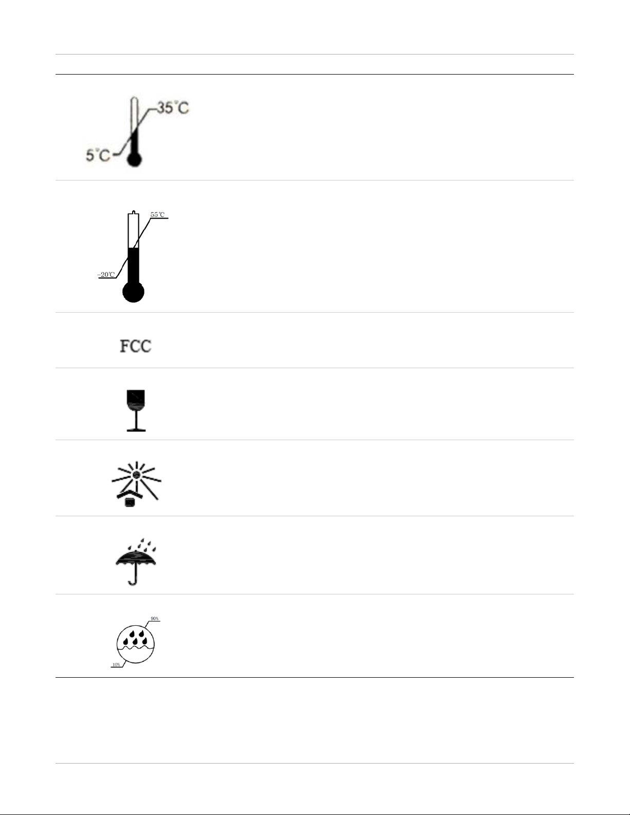
This indicates operational temperature limits.
This indicates storage temperature limits.
This indicates the product radiates a wireless signal.
Package symbol: Fragile
Package symbol: Keep away from sunlight.
Package symbol: Keep dry.
This indicates the humidity limits.
AJ4309 | 2019-08-13 1–3
Safety and Regulatory Information
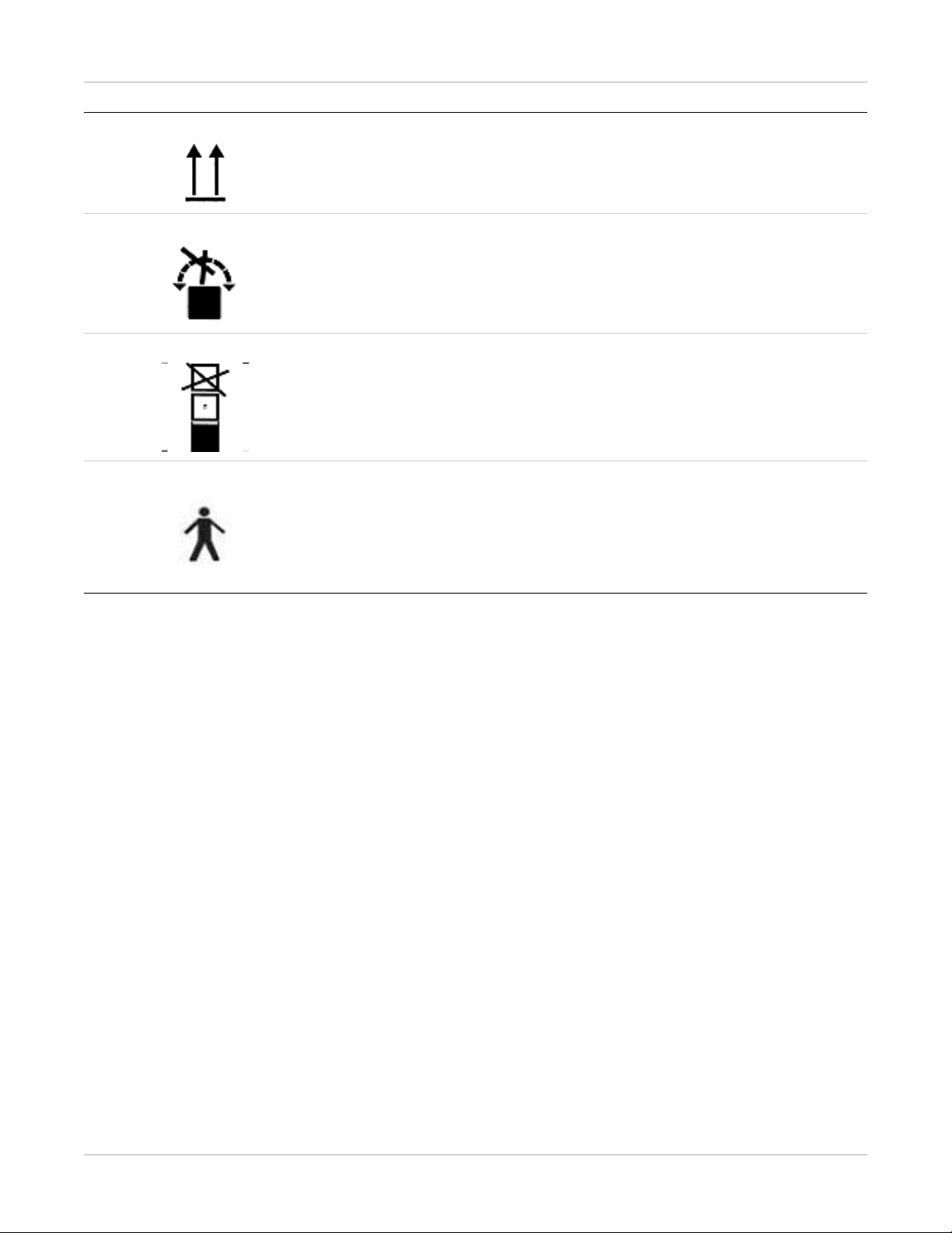
Keep the product upright.
Do not roll the transportation packaging.
This indicates the stacking limit number.
This indicates a Type-B applied part.
1–4 AJ4309 | 2019-08-13
Cautions
Environment for Installation and Use
Environment for Installation and Use
Safety and Regulatory Information
WARNING:
Do not use or store the product near flammable chemicals such as alcohol,
thinner, benzene, etc.
Chemicals that are spilled or evaporated may result in fire or electric shock
through contact with electric parts inside the product. Also, some disinfectants are flammable. Be sure to take care when using them.
WARNING:
Do not connect the equipment with anything other than the specified
connectors to avoid fire or electric shock.
WARNING:
Keep all patients with active implantable medical devices away from the
product.
AJ4309 | 2019-08-13 1–5

Safety and Regulatory Information
CAUTION:
Do not install the product in any of the locations listed below to avoid failure,
malfunction, falling, fire, or injury.
• Close to facilities where water is used
Installation and Environment of Use
• Where there is exposure to direct sunlight
• Close to the air outlet of an air conditioner or ventilation equipment
• Close to a heat source such as a heater
• Where the power supply is unstable
• In a dusty environment
• In a saline or sulfurous environment
• Where temperature or humidity is high
• Where there is freezing or condensation
• In areas prone to vibration
• On an incline or in an unstable area
CAUTION:
Do not allow cables to become tangled to avoid a malfunction of the
product.
Do not get your feet caught by a cable to avoid tripping and injury.
Installation and Environment of Use
CAUTION:
Non-medical equipment such as battery chargers and access point and
infrared register tools cannot be used in the vicinity of a patient.
1–6 AJ4309 | 2019-08-13
Power Supply
Power Supply
Safety and Regulatory Information
WARNING:
Do not operate the product with a power supply other than the one indicated
on the rating label to avoid fire or electric shock.
WARNING:
Do not handle the product with wet hands to avoid electric shock that could
result in death or serious injury.
WARNING:
Do not place heavy object on cables and cords. Co not pull, bend, bundle, or
step on them to prevent damage to the sheath. Do not alter them.
Avoid damage to the cords, which could result in fire or electric shock.
WARNING:
Do not supply power from the same AC outlet to more than one product to
avoid fire or electric shock.
WARNING:
Do not turn on system power when condensation has formed on the equipment to avoid fire or electric shock.
AJ4309 | 2019-08-13 1–7
Safety and Regulatory Information
WARNING:
Do not connect multiple portable socket outlets or extension cords to the
system to avoid fire or electric shock.
Power Supply
WARNING:
Connect this product only to a power supply with protective earth to avoid fire
or electric shock.
WARNING:
Do not use the adapter cord when connecting the panel to a patient.
1–8 AJ4309 | 2019-08-13
Power Supply
Safety and Regulatory Information
WARNING:
Securely insert the power cord into the AC outlet to avoid a contact failure.
If a contact failure occurs or if metal objects come in contact with the exposed
metal prongs of the plug, fire or electric shock may result.
WARNING:
Be sure to turn off the power before connecting or disconnecting the cords to
avoid an electric shock that could result in death or serious injury.
WARNING:
Be sure to hold the plug or connector to disconnect the cord.
Power Supply
If you pull the cord, the core wire may be damaged, resulting in fire or electric
shock.
CAUTION:
• Always connect a three-core power cord plug to a grounded AC power
outlet.
• Keep the outlet free of obstacles for easy access to disconnect the plug at
any time and in an emergency.
• Be sure to ground the product to an indoor grounded connector. Be sure
to connect all the grounds of the system to common ground.
CAUTION:
Do not use any power source other than the one provided with the product
to prevent leakage that could result in fire or electric shock.
AJ4309 | 2019-08-13 1–9
Safety and Regulatory Information
Handling
WARNING:
No modification is allowed. Never disassemble or modify the product to avoid
fire or electric shock.
The product incorporates parts that may be hazardous or cause electric shock
Touching them may cause death or serious injury.
Handling
WARNING:
Do not place an object on top of the product. The object may fall and cause
an injury.
Metal objects such as needles or clips that fall into the product or spilled liquid
may result in fire or electric shock.
Handling
WARNING:
Do not strike, drop, or cause a strong jolt to the product to prevent damage
and avoid fire or electric shock.
WARNING:
Do not place the product and pointed objects together to prevent damage.
If so, it should be used in Bucky.
WARNING:
Have the patient take a fixed posture and do not let the patient touch parts
unnecessarily.
If the patient touches connectors or switches, it may result in electric shock or
malfunction.
1–10 AJ4309 | 2019-08-13

Handling
Safety and Regulatory Information
CAUTION:
Do not spill liquid or chemicals onto the equipment. Do not allow an injured
patient’s blood or body fluids contact with the equipment.
Doing so may result in fire or electric shock.
In such a situation, protect the equipment with a disposable cover as necessary.
CAUTION:
For safety Turn OFF the power and remove the plug for all equipment when
not used.
Handling
CAUTION:
Handle the product carefully.
Do not submerge the product in water.
CAUTION:
The internal image sensor may be damaged if struck or dropped. If the product
is dropped, the drop sensor inside would record and the product would not
be under warranty.
AJ4309 | 2019-08-13 1–11
Safety and Regulatory Information
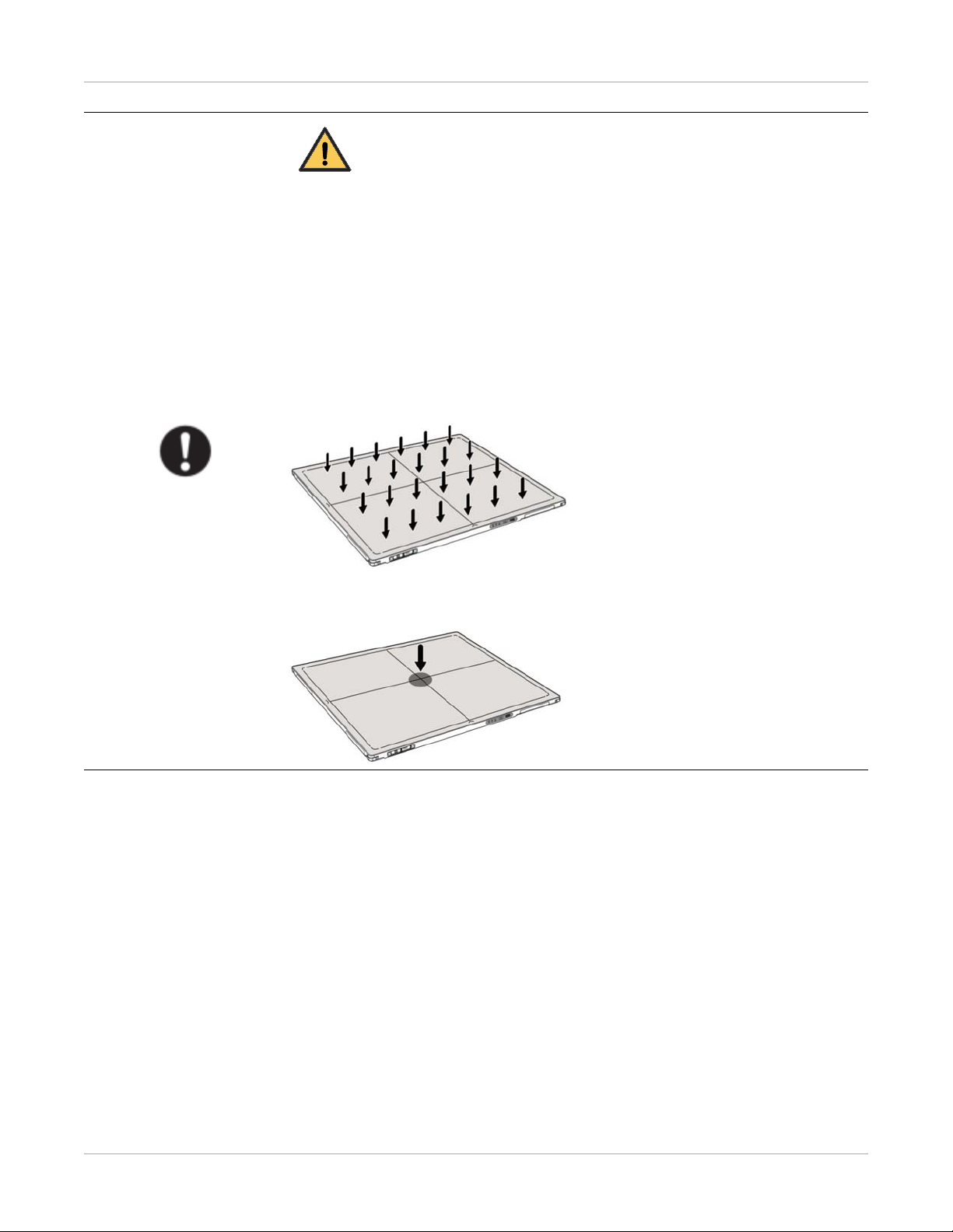
CAUTION:
Do not place excessive weight on the panel to avoid damage to the internal
image sensor and an incorrect image.
Patients stand on the product temporarily, and the intended weight can be
135 kg.
Based on the internal TFT character, cannot load the dynamic forces due to
loading from persons
Load Limit
Uniform load:150 kg over the whole area of the surface
Handling
Local load:100 kg on an area 4 cm diameter
1–12 AJ4309 | 2019-08-13
Handling
Safety and Regulatory Information
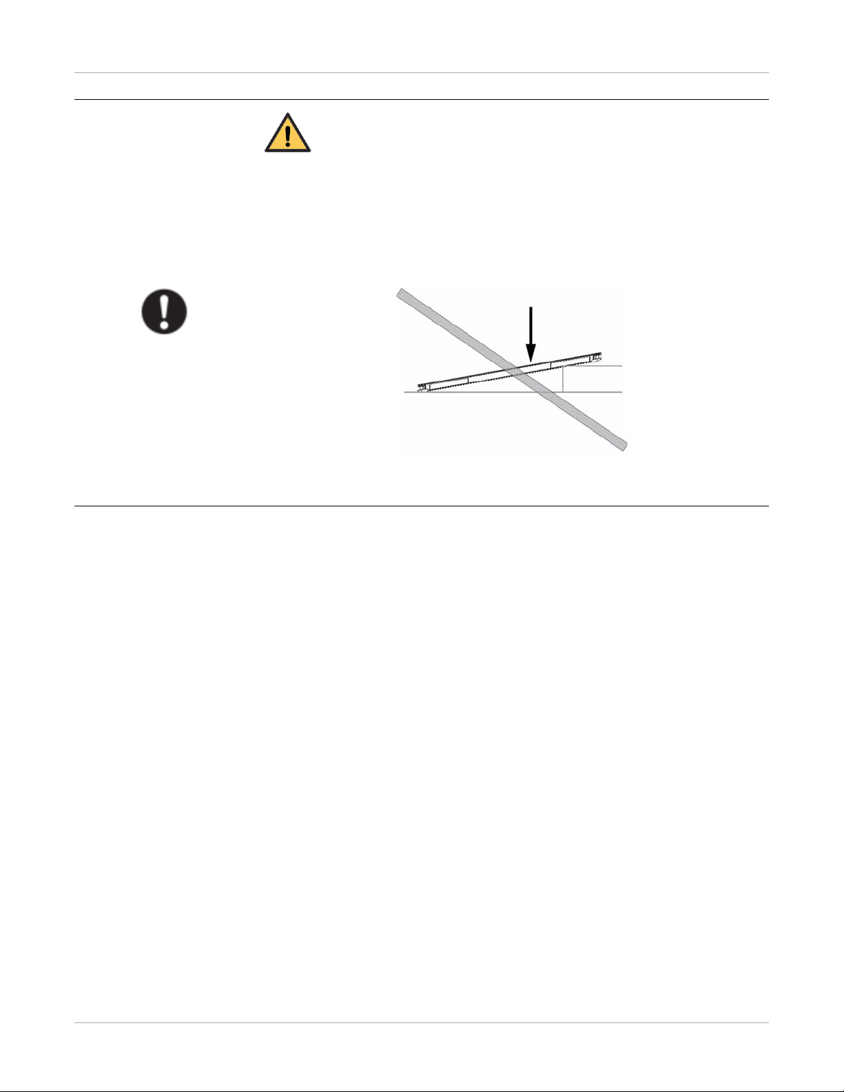
CAUTION:
Be sure to use the product on a flat surface to prevent the product from
bending and doing damage to the internal image sensor. Be sure to securely
hold the product while using it in an upright positions to prevent the product
from tipping or flipping over, resulting in injury to the user or patient damage
to the inner device.
Keep the same pressure on the product when acquiring an image to avoid an
incorrect image.
AJ4309 | 2019-08-13 1–13
Safety and Regulatory Information
CAUTION:
• Do not use the product close to fire or in high temperature.
• Do not invert the positive and negative poles.
• Do not allow the product to make contact with metal to avoid a short
• Do not insert sharp objects into the battery.
• Do not strike the battery.
Handling
• Do not stand on the battery.
• Do not use the battery outside of the guidelines.
• Do not dispose of the battery or change the inner structure.
• Do not submerge the battery in water. When in use, do not allow the
circuit.
battery to have contact with water. Store the battery in a dry place.
• Use a charger to charge the battery following the GB 9706.1 Standards
provided.
• Do not replace the battery provided with one from another company.
• Do not use a damaged charger to charge the battery.
• Only qualified personnel may replace the battery inside the main unit.
• Do not touch the output connector for the adapter.
1–14 AJ4309 | 2019-08-13
Maintenance and Inspection
WARNING:
• Turn off the power of the product and disconnect the power cord of the
adapter before cleaning.
• Never use alcohol, ether, and other flammable cleaning agent for safety.
Never use methanol, benzene, and acid to avoid corrosion on the equipment.
• Do not place the product in liquid.
Safety and Regulatory Information
Maintenance and Inspection
WARNING:
Make sure that the surface and connectors are dry before turning on the
product to avoid fire or electric shock.
WARNING:
Clean the power cord connector periodically. Disconnect the connector from
the AC outlet. Use a dry cloth to remove dust or dirt from the connector, its
periphery, and the AC outlet.
If the cord is kept plugged in for a long time in a dusty, humid, or sooty place,
dust around the plug will attract moisture; this could cause insulation failure
that may result in a fire.
WARNING:
For safety reasons, be sure to turn off the power when performing the inspections indicated in this manual to avoid electrical shock.
AJ4309 | 2019-08-13 1–15

Safety and Regulatory Information
When a Problem Occurs
When a Problem Occurs
WARNING:
If any one of the following occurs, immediately disconnect the power cord of
the adapter or battery, and contact your sales representative or local dealer:
• When there is smoke, an odd odor, or abnormal sound
• When liquid has spilled into the equipment or a metal object has entered
through an opening
• When the product has been dropped and damaged
Medical Equipment Classification
Type of protection against electrical shock External electrical power source equipment Class I
Equipment (medical approved adapter)
Internal electrical power source equipment (battery)
Degree of protection against electrical shock Type-B applied part
Degree of protection against ingress of water IPX1
Mode of operation Continuous operation
Flammable anesthetics Not suitable for use in the presence of a flammable
anesthetic mixture with air or with oxygen or nitrous
oxide
Not suitable for use in an oxygen-rich environment
1–16 AJ4309 | 2019-08-13

Safety and Regulatory Information
Standards
ISO 13485:2016 Medical devices — Quality management systems —
Requirements for regulatory purposes
IEC 60601-1:2005/AMD1:2012 Medical electrical equipment — Part 1: General
requirements for basic safety and essential performance
IEC 60601-1-2:2014/EN60601-1-2:2015 Medical electrical equipment — Part 1-2: General
requirements for basic safety and essential performance — Collateral standard: Electromagnetic disturbances v Requirements and tests
IEC 60601-2-54:2018/EN 60601-2-54:2019 Medical electrical equipment — Part 2-54: Particu-
lar requirements for the basic safety and essential
performance of X ray equipment for radiography
and radioscopy
IEC 62133-2:2017 Secondary cells and batteries containing alkaline or
other non-acid electrolytes — Safety requirements
for portable sealed secondary lithium cells, and for
batteries made from them, for use in portable
applications — Part 2: Lithium systems
IEC 62220-1-1:2015/EN 62220-1-1:2015 Medical electrical equipment — Characteristics of
digital X-ray imaging devices — Part 1-1: Determination of the detective quantum efficiency - Detectors used in radiographic imaging
IEC 62304:2006/AMD1:2015 Medical device software — Software life-cycle pro-
cesses
IEC 62366-1:2015/IEC 62366:2007/EN62366:2008 Medical devices — Part 1: Application of usability
engineering to medical devices
IEC 60601-1-6:2010+A1:2013 Medical electrical equipment — Part 1-6: General
requirements for basic safety and essential performance — Collateral standard: Usability
EN ISO14971:2012 Medical device — Application of risk management
to medical devices
ANSI/AAMI
ES60601-1:2005/(R)2012+A1:2012+C1:2009/(R)2
012+A2:2010/(R)2012
Medical electrical equipment — Part 1: General
requirements for basic safety and essential performance (IEC 60601-1:2005, MOD)
AJ4309 | 2019-08-13 1–17

Safety and Regulatory Information
CAN/CSA-C22.2
No.60601-1:14
Medical electrical equipment — Part 1: General
requirements for basic safety and essential performance
ISO 15223-1:2016/ EN ISO 15223-1:2016 Medical devices — Symbols to be used with medi-
cal device labels, labeling and information to be
supplied-Part 1: General requirements
1–18 AJ4309 | 2019-08-13

Safety and Regulatory Information
Emissions and Immunity Compliance to the IEC60601-1-2 Standard
Electromagnetic Emissions
Emissions Test Compliance Electromagnetic Environment
RF emissions CISPR 11
Group 1, Class B
Harmonic distortion IEC 61000-3-2
Class A
Voltage fluctuations and flicker IEC 61000-3-3
Compliance
The Carestream Focus 35C Detector uses RF
energy only for its internal function. Therefore, its RF emissions are very low and are
not likely to cause any interference in
nearby electronic equipment.
The Carestream Focus 35C Detector is suitable for use in all establishments, including
domestic establishments and those directly
connected to the public low voltage power
supply network that supplies buildings used
for domestic purposes.
Electromagnetic Immunity
Emissions Test EMC Standard
Electrostatic discharge IEC 61000-4-2 ±8 kV contact
Professional healthcare facility environment
±2 kV, ±4 kV, ±8 kV, ±15 kV air
Test Levels
Radiated RF EM field IEC 61000-4-3 3 V/m
80 MHz–2.7 GHz
80 % AM at 1 kHz
Proximity fields from RF wireless
communications equipment
Rated power frequency magnetic fields
AJ4309 | 2019-08-13 1–19
IEC 61000-4-3 Refer to Proximity Fields From RF Wireless
Communications Equipment
IEC 61000-4-8 30 A/m
50 Hz or 60 Hz

Safety and Regulatory Information
Proximity Fields From RF Wireless Communications Equipment
Test Frequency
(MHz)
Band (MHz)
Professional healthcare facility environment
Test Levels
385 380–390 Pulse modulation 18 Hz, 27 V/m
450 430–470 FM, ±5kHz deviation, 1 kHz sine, 28 V/m
710
704–787 Pulse modulation 217 Hz, 9 V/m745
780
810
800-–960 Pulse modulation 18 Hz, 28 V/m870
930
1720
1700–1990 Pulse modulation 217 Hz, 28 V/m1845
1970
2450 2400–2570 Pulse modulation 217 Hz, 28 V/m
5240
5100–5800 Pulse modulation 217 Hz, 9 V/m5500
5785
Input AC Power Port
Emissions Test EMC Standard
Professional healthcare facility environment
Electrical fast transients/burst IEC 61000-4-4 ±2 kV
100 kHz repetition frequency
Surges
Line-to-line
IEC 61000-4-5 ±0.5 kV, ±1kV
Test Levels
1–20 AJ4309 | 2019-08-13

Emissions Test EMC Standard
Safety and Regulatory Information
Test Levels
Professional healthcare facility environment
Surges
IEC 61000-4-5 ±0.5 kV, ±1kV, ±2 kV
Line-to-ground
Conducted disturbances
induced by RF fields
IEC 61000-4-6 3 V, 0.15 MHz–80MHz
6 V in ISM bands between 0.15 MHz and
80 MHz
80 % AM at 1 kHz
Voltage dips
IEC 61000-4-11
0 % UT; 0.5 cycle
At 0 º, 45 º, 90 º, 135 º, 180 º, 225 º, 270 º and
315 º
Voltage dips IEC 61000-4-11 0 % UT; 1 cycle
and
70 % UT; 25/30 cycles
Single phase: at 0 º
Voltage interruptions IEC 61000-4-11 0 % UT; 250/300 cycles
Signal Input/Output Parts Port
Emissions Test EMC Standard
Professional healthcare facility environment
Electrostatic Discharge IEC 61000-4-2 ±8 kV contact
±2kV, ±4kV, ±8kV, ±15kV air
Electrical fast transients/burst IEC 61000-4-4 ±1 kV
100 kHz repetition frequency
Conducted disturbances
induced by RF fields
IEC 61000-4-6 3 V, 0.15 MHz–80 MHz
6 V in ISM bands between 0.15 MHz and 80
MHz
80 % AM at 1 kHz
Test Levels
AJ4309 | 2019-08-13 1–21

Safety and Regulatory Information
Reference Cables Provided Against EMC
Cable
Recommended
Cable Length
Shielded or
Unshielded
Number Cable Classification
AC Power Cable 3 m Unshielded 1 pcs AC Power
DC Power Cable 3.5 m Unshielded 1 pcs DC Power
LAN Cable
3 m Shielded 1 pcs Signal
(configuration mode)
Important Information Regarding Electromagnetic Compatibility (EMC)
Focus 35C requires special precautions regarding EMC and needs to be installed only by
Carestream or authorized personnel and put into service according to EMC information
provided in the user manual.
Focus 35C in use may be susceptible to electromagnetic interference from portable and
mobile RF communications such as mobile (cellular) telephones. Electromagnetic
interference may result in incorrect operation of the system and create a potentially
unsafe situation. The minimum distance between the panel and other equipment should
be larger than 12 inch.
Focus 35C conforms to this EN60601-1-2:2015 standard for both immunity and emissions.
Nevertheless, special precautions need to be observed.
The use of accessories, transmitters, and cables other than those specified by this user
manual, with the exception of accessories and cables sold by Carestream as Focus 35C
replacement parts for inner components, may result in increased emission or decreased
immunity.
1–22 AJ4309 | 2019-08-13

Radio Frequency Compliance
Country Item
FCC Part 15.107 Sub part (b) / 15.109 (g) Sub part B
U.S.A
European Union
FCC Compliance
• The panel has been tested to comply with limits for a Class B digital device, pursuant
to part 15 of FCC Rules. These limits are designed to provide reasonable protection
against harmful interference in a residential installation.
• Operation is subject to the following two conditions.
The panel may not cause harmful interference.
The panel must accept any interference received, including interference that may
cause undesired operation.
• The panel generates, uses, and radiates radio frequency energy and, if not installed
and used in accordance with the instruction, may cause harmful interference to radio
communications. However, there is no guarantee that interference will not occur in
a particular installation. If the panel does cause harmful interference to radio or
television reception, which can be determined by turning the panel off and on, the
user is encouraged to correct the interference by one or more of the following
measure.
– Reorient or relocate the antenna.
– Increase the separation between the panel and receiver.
– Connect the panel into an outlet different from the receiver is connected.
– Consult the distributor or an experienced radio/TV technician for help.
FCC Part 15 Sub part E 15.407
FCC Part 15 Sub part C 15.247
ETSI EN 301 489-1 V1.8.1 (EMC)
ETSI EN 301 489-17 V2.1.1 (EMC)
EN 300 328 V.1.7.1; EN 301 893 V1.6.1 (RF)
EN 62311:2008 (RF Exposure)
ETSI EN 300 328 V1.7.1; EN 301 893, V1.5.1 (Radio Spectrum)
Safety and Regulatory Information
Correction and Calibration Template Generation
Correction and calibration should be performed after installation and every six months.
The new correction and calibration should be performed after any major change on the
system settings and hardware configuration.
AJ4309 | 2019-08-13 1–23

Safety and Regulatory Information
Battery Safety Standards
Standards Description
Secondary cells and batteries containing alkaline or other
CAN/CSA E62133:13 1st Ed. Rev.
UL 62133, 1st Ed. Rev.
UL 2054 Household and commercial batteries
IEC 62133-2:2017
non-acid electrolytes — Safety requirements for portable sealed
secondary cells, and for batteries made from them, for use in
portable applications First Edition
Secondary cells and batteries containing alkaline or other
non-acid electrolytes — Safety requirements for portable sealed
secondary cells, and for batteries made from them, for use in
portable applications First Edition
Secondary cells and batteries containing alkaline or other
non-acid electrolytes — Safety requirements for portable sealed
secondary lithium cells, and for batteries made from them, for
use in portable applications — Part 2: Lithium systems
UN38.3
United Nations Recommendations on the Transport of Dangerous Goods Manual of Tests and Criteria
ST/SG/AC.10/11/Rev.5/Amend.1 and Amend.2
1–24 AJ4309 | 2019-08-13

Safety and Regulatory Information
Intended Use and Essential Performance
Intended Use
Focus 35C is indicated for digital imaging solutions designed for providing general
radiographic diagnosis of the human anatomy. It is intended to replace radiographic
film/screen systems in all general purpose diagnostic procedures. This panel provides
digital X ray imaging for diagnosis of disease, injury, or any applicable health problem.
The image is obtained as the result of an X-ray passing through the human body and
detected by detector.
Carestream would provide hardware and software support for system integration. This
panel is not intended for mammography and extra-oral X-ray applications.
Essential Performance
For Focus 35C, the intended use and the result of risk management, getting imaging and
function of data transmission is defined as essential performance.
Getting qualified dark image proves that essential performance does not influence the
intended use. For the method of getting dark image, see the Installation and Operation
sections.
Application Specification
Patient Population
• Age: except for children
• Weight: not relevant
• Health: not relevant
• Nationality: multiple
• Patient state: patient is not user
• Gender: except for pregnant women
Intended Operator
All procedures should be carried out by an operator who has completed the professional
training offered by the company’s customer service staff.
Life Time
Lifetime: 7 years without frequency limit
AJ4309 | 2019-08-13 1–25

Safety and Regulatory Information
1–26 AJ4309 | 2019-08-13

2
Overview
The Focus 35C Detector is a cassette-size, wireless x-ray flat panel detector based on
amorphous silicon thin-film transistor technologies. It is developed to provide the highest
quality of radiographic images with an active matrix of 2304 × 2800 with 150 um pixel
pitch. The detector supports wireless communication between the panel and the
workstation and is powered by an internal battery.
Scope
This manual contains information about the Focus 35C. Information in the manual,
including the illustrations, is based on a prototype. If your system configuration does not
have features described in this manual, the information does not apply to your detector.
Features
• Wireless static flat panel detector used for general radiography
• Cassette-size
• Sync-shot exposure trigger
• CsI scintillation screen
• Easy-to-change cable and easy-to-update firmware
• Battery recycling
AJ4309 | 2019-08-13 2–1

Overview
Components and Specifications
Product Components
Component Description
Detector
Figure 1: External Signals
Figure 2: Input Control Panel
2–2 AJ4309 | 2019-08-13

Item Description Notes
A DC jack Not used
B Ethernet port For service
C Detector indicator Detector indicator of control panel
D Power button Power button of control panel
E Mode button Mode switch
F Antenna
Battery
Overview
Item Description Notes
A Battery label
B Battery interface 8 pin battery connector
C Pilot pin
D Indicator Installation direction indicator
AJ4309 | 2019-08-13 2–3

Overview
Battery Charger
Item Description Notes
A Battery Interface A 8 pin battery connector
B Battery Interface B Not used
C Battery Interface C Not used
D Indicator The indicator definition is as follow
E The limit ball plug /
F Hand Pull Position /
G AC Jack 220V (ac) input
Battery Charger Indicator
Item Name
APower Indicator
B Charging Indicator
C Charge Full Indicator
2–4 AJ4309 | 2019-08-13

X Indicator Operating Status
Overview
All off
A indicator on
A indicator on
B and C alternately blink 2 times
A and B indicator on
A and C indicator on
No power input
• AC power input
• Multiple batteries inserted
Battery insertion self test
Battery charging
Battery capacity full, charging
stops
A indicator on
B and C alternately blinking
Two or more batteries charging cannot be charged at the same time. Charging will
automatically stop if more than one battery is inserted.
Battery is not charging properly
AJ4309 | 2019-08-13 2–5

Overview
Product Specifications
Detector
Model Focus 35C
Image Sensor a-Si (amorphous silicon) TFT
Pixel Size 150 μm
Active Array 2304 x 2800
Item Specifications
Active Area (H x V) 345.6 x 420.0 mm (13.6 x 16.5 in.)
Gray Scales 16 bit
Spatial Resolution 3.3 Lp/mm
Image Acquisition Time (Wireless)
Both AP Mode and Client Mode
Preview acquisition time: 3 sec.
Processed acquisition time: 5 sec.
Cycle Time Min. 8 sec.
Power Consumption Max. 18 W
Dimension (L × W × H) 460.0 x 384.0 x 15.0 mm (18.1 x 15.1 x
0.6 in.)
Weight (with one battery) 3.43 kg (7.56 lb)
Image Transfer Wireless: IEEE802.11a/b/g/n/ac
Data Transmission Rate (Wireless) 802.11b: Max. 11 Mbps
802.11a/g: Max. 54 Mbps
802.11n: Max. 300 Mbps (MIMO 2 x 2)
802.11ac: Max. 867 Mbps(MIMO 2 x 2)
2–6 AJ4309 | 2019-08-13

Battery
Overview
Item Specifications
Model Battery-KV
Rated capacity Typ. 4180 mAh @ Discharge 0.2C
Nominal voltage 10.8 V
Charge voltage 12.6 ± 0.05 V
Discharged end voltage 9 V
Charging method CC-CV
Operating temperature Charge 0–60 °C (32–140 °F)
Discharge 0–60 °C (32–140 °F)
Storage temperature ≤3 month -20 °- +45 ° (-4–113 °F)
≤6 month -20°- +35 ° (-4–95 °F)
Relative humidity 5 %~95 %
Dimension (L × W × H) 210 x 115 x 7.5 mm
Weight 0.28 kg (0.62 lb)
AJ4309 | 2019-08-13 2–7

Overview
Battery Charger
Item Specifications
Model Charger-Combo
Simultaneous Charging 1 Battery Pack
Full Charging Time ≤ 3 hr
Rated Power Supply 90~264 V (ac)
Dimension (L × W × H) 240.0 x 184.0 x 38.0 mm (9.4 x 7.2 x
1.52 in.)
Weight 0.55 kg (1.2 lb)
Power Supply
Item Specifications
DC Power 24V (dc), 0.75A
Battery Package 10.8V (dc), 1.6A
The product must be used with the approved adapter and CB certificate number
SG PSB-MD-00191.
2–8 AJ4309 | 2019-08-13

Wireless Communication
Item Specifications
Wireless Standard IEEE 802.11 a/b/g/n/ac
Frequency Range 2.412~2.472 GHz: ch1~ch13
5.18~5.22 GHz: ch36~ch48
5.745~5.85 GHz: ch149~ch165
Data Transmission Rate 802.11b: Max. 11 Mbps
802.11a/g: Max. 54 Mbps
802.11n: Max. 300 Mbps (MIMO 2x2)
802.11ac: Max. 867 Mbps(MIMO 2x2)
Modulation 802.11b:
CCK, DQPSK, DBPSK
802.11a/g/n:
64 QAM, 16 QAM, QPSK, BPSK
802.11ac:
256 QAM, 64 QAM, 16 QAM, QPSK, BPSK
Overview
Transmission Power Max.17 dBm
Security WPA, WPA-PSK, WPA2, WPA2-PSK, WEP 64
bit & 128 bit
Antenna 2 dual band inner antenna
AJ4309 | 2019-08-13 2–9

Overview
Mechanical Outlines
Use Environment
Temperature
Te mp e ra t ur e
Operating 5–35 °C
Change Humidity
< 1k/min 10 %–90 % RH700–1060 hPa <10 kp/min
(41–95 °F)
Storage -20–55 °C
< 1k/min 5 %–95 % RH 700–1060 hPa <10 kp/min
(-4–131 °F)
Focus 35C detectors shall operate at a specified altitude of not more than 3000.0 m (9842.5 ft). The environment specific is only for the detector.
Atmospheric
Pressure Pressure Change
(1 kp=1.0197E-5Pa)
(1 kp=1.0197E-5Pa)
2–10 AJ4309 | 2019-08-13

IT Network
Purpose for IT-network
Transmission of image data and command/status communication between the detector
and the workstation.
Required Features
Wireless communication follows IEEE 802.11a/b/g/n/ac protocol. It works on 2.4 GHz and
5 GHz.
It supports at least 2 routers.
Hazardous Situations from Failure of the IT Network
• Incompatibility of the operating system is not compatible
• Inability to update or change software
Overview
• Incompatibility of the interface
• Inconsistency of interface or format leads to data distortion
• Data transfer protocol error
• Data output failure
Required Configuration
The wireless card and the detector must work on the same IP segment such as
192.168.8.XXX.
They must support IEEE 802.11a/b/g/n/ac.
Technical Specifications
Item Specifications
Wireless Standard IEEE 802.11a/b/g/n/ac
Frequency Range 2.412-2.472 GHz: ch1-ch13
5.18-5.22 GHz: ch36-ch48
5.745-5.85 GHz: ch149-ch165
AJ4309 | 2019-08-13 2–11

Overview
Item Specifications
Data Transmission Rate 802.11b: Max. 11 Mbps
802.11a/g: Max. 54 Mbps
802.11n: Max. 300 Mbps (MIMO 2x2)
802.11ac: Max. 867 Mbps (MIMO 2x2)
Modulation 802.11b: CCK, DQPSK, DBPSK
802.11a/g/n: 64 QAM, 16 QAM, QPSK, BPSK
802.11ac: 256 QAM, 64 QAM, 16 QAM, QPSK, BPSK
Security WPA, WPA-PSK, WPA2, WPA2-PSK, WEP 64 bit, and 128 bit
Intended Information Flow
The detector sends the acquired image data to the workstation. The workstation sends
the user's commands to the detector. Please refer to the operation manual of the console
for detail.
Hazardous Situations Resulting From Failure of the IT-network
• Failure of completing essential performance
• Failure of finishing configuration of product
• Incompatibility of operating system
• Failure of change or update to software
• Compatibility of interface
• Data transfer protocol error
• Inconsistency of interface or format leads to data distortion
• Data output failed
Warning
Connection of the main unit to an IT network that includes other equipment could result
in previously unidentified risks.
The manufacturer of the x-ray machine should identify, analyze, evaluate, and control
these risks; subsequent changes to the IT-network could introduce new risks and require
additional analysis.
Changes to the IT Network
• Changes in the IT network configuration
2–12 AJ4309 | 2019-08-13

• Connection of additional items to the IT network
• Disconnecting of items from the IT network
• Update of equipment connected to the IT network
Overview
AJ4309 | 2019-08-13 2–13

Overview
Service Information
Product Lifespan
The estimated product lifetime is up to 7 years under appropriate regular inspection and
maintenance (battery 5 years).
Regular Inspection and Maintenance
In order to ensure the safety of patients and operator, and to maintain the performance
and reliability of the panel, be sure to perform regular inspections at least once a year. If
necessary, clean the panel, make adjustments, or replace consumables such as fuses etc.
There may be cases where an overhaul is recommended depending on conditions.
Contact Carestream service or your local dealer for regular inspection or maintenance.
Repair
If the problem cannot be solved, contact Carestream service or your local dealer for
repairs. Please refer to the label and provide the following information:
Product Name:
Series Number:
Description of Problem: (as clearly as possible)
Replacement Parts Support
Main parts (those required to maintain the function of the product) needed to repair the
product will be stocked for 5 years after discontinuance of production.
2–14 AJ4309 | 2019-08-13

Disposal
CAUTION:
Do not dispose of this product with your residential or commercial waste. Improper handling of
this type of waste could have a negative impact on health and on the environment. Some
countries or regions, such as the European Union, have set up systems to collect and recycle
electrical or electronic waste. Contact your local authorities for information about dropping off
waste products for recycling. If collection systems are not available, call Carestream Customer
Service for assistance.
Overview
In the European Union, this symbol indicates that when the last user wishes
to discard this product, it must be sent to appropriate facilities for recovery
and recycling. See http://recycle.carestreamhealth.com for additional information on the collection and recovery programs available for this product.
AJ4309 | 2019-08-13 2–15

Overview
2–16 AJ4309 | 2019-08-13

3
Installation
Panel Installation
Install the Detector Battery
The detector can be powered by the battery package or DC power. The detector will be
activated as soon as power is supplied and will power off as soon as power is removed.
1. Make sure that the connectors for the battery and battery compartment are aligned.
AJ4309 | 2019-08-13 3–1

Installation
2. Slide the battery into the battery compartment.
Note:
Make sure the battery level is >10 % of full capacity.
3. Slide the two battery lock levers toward the center of the detector..
Power on the Detector
On the control panel, the power button is used to power the detector on and off.
To power on the detector, press and hold the power button for 4 seconds. The detector
must either have a battery installed with >10 % charge or have the DC power connected.
To power off the detector, press and hold the power button for 4 seconds.
3–2 AJ4309 | 2019-08-13

To reset the detector, press and hold the power button for 8 seconds.
Power Indicator
After booting up, the user can check the status LED indicator.
Installation
Operating Status
Power Indicator Lighting Status
Operating Battery Capcity DC Input
OFF Power OFF -- --
Orange ON Power ON ≤20% No
Green ON Power ON
• Battery capacity ≥20 %, no DC
input
• DC input, no battery
Orange Blinking Power OFF <20 % Yes
Green and Orange
Power OFF ≥20 % and <95 % Yes
Blinking
AJ4309 | 2019-08-13 3–3

Installation
Operating Status
Power Indicator Lighting Status
Operating Battery Capcity DC Input
Green Fast Blinking Power OFF ≥95 % and <100 % Yes
OFF Power OFF =100 % Yes
Link Indicator
Power Indicator Lighting Status Description
Off
Green On
Blue On
Blue Blinking
Green and Blue Blinking
• Shut down
• Wired connection broken and wireless connection
not ready
Wired connection is built
• Client mode, wireless connection is built
• AP mode, wireless AP is ready
Client mode, no connection is built
Client mode, no connection is built
3–4 AJ4309 | 2019-08-13

Status Indicator
Power Indicator Lighting Status Description
Installation
Off
Green On
• Shut down
• Exposure prohibit
Exposure enable
Green Blinking
Exposure enable
Orange On
Error
Orange Blinking
Safety mode
Mode Indicator
Power Indicator Lighting Status Description
Off
Green On
Blue On
Blue and Green Blinking
• Shut down
• Wired connection is built
AP mode, wireless AP is ready
Client mode, wireless client is ready
Initialization
AJ4309 | 2019-08-13 3–5

Installation
Button Function
Power Mode Note
Action FPD Status
Power ON
Short hold No action Hold for 4 seconds
Forced restart Long hold No action
Power OFF
Exit the battery from
ship mode
Press 3 times No action
Enter safety mode Short hold Long hold
Forced restart
Long hold No action
Enter/exit sleep mode Double click No action
Hold for more than 7 seconds.
Release the power button
when the power indicator is
ON.
Release after two short
presses (interval < 1second).
Power button: hold for 4 seconds
Mode button: hold for 7 seconds
Hold for more than 7 seconds, when the Power indicator is OFF and then ON,
release Power button.
Release after two short
presses (interval <1second)
Power OFF Short hold No action
Power ON
the Power button when the
power indicator is OFF.
Hold for 4 seconds, Release
1. Hold the Mode button
hold for 7 seconds.
2. Press the Power button 3
times.
Restore default configuration
Trip le che ck
Short hold
Long hold
3. Short hold the Power
button for 4 seconds.
3–6 AJ4309 | 2019-08-13

Install the Detector Battery Charger
1. Remove the battery from the battery charger.
2. Insert battery into battery charger in the orientation shown below.
Installation
3. Press the battery down into the battery compartment.
AJ4309 | 2019-08-13 3–7

Installation
Detector Battery Lock and Activation
To ensure the safety of the battery during transportation or storage, the battery can be
set to ship mode where it is locked and will not provide any voltage output.
Enter Ship Mode
Method Steps
Factory configuration
Web write in
Exit Ship Mode
Web exit
1. Connect the adapter to the detector and
power it on.
2. Connect the other end of the adapter to
the PC.
3. Insert the battery into the detector.
4. Open a web browser and enter the
following address:
http://10.0.1.150/cgi-bin/shipmode.cgi?action=on
The battery is placed in ship mode.
Method Steps
1. Connect the adapter to the detector and
power it on.
2. Connect the other end of the adapter to
the PC.
3. Insert the battery into the detector.
4. Open a web browser and enter the
following address:
http://10.0.1.150/cgi-bin/shipmode.cgi?action=off
The detector exits ship mode.
3–8 AJ4309 | 2019-08-13

Method Steps
Installation
Adapter + FPD
Charger
1. Connect the adapter to the detector and
power it on.
2. Insert the battery into the detector.
3. Press the power button for approximately
4 seconds to shut down the detector.
4. In the shutdown state, press the power
button 3 times to exit ship mode.
1. Power on the charger.
2. Insert the battery into the charger for 3 to
5 seconds to exit ship mode.
AJ4309 | 2019-08-13 3–9

Installation
3–10 AJ4309 | 2019-08-13

4
Operation
Notes for Using
Do the following to ensure that the detector functions correctly.
Before Exposure
Inspect the detector daily and confirm it is working properly.
Check that there is no condensation on the any of the surfaces of the detector.
Condensation can be caused by the sudden heating of the room in cold areas. If this
occurs, wait until the condensation evaporates before performing an exposure or
problems may occur with the quality of captured images. When changing the
temperature in an air-conditioner environment, be sure to raise or lower the
temperature gradually.
The product should be warmed up for 15 minutes before exposure or updating the gain
map and defect map.
Make sure exposure rate is over 900 nGy/s @70 KV.
Make sure the wave form of the energy going to the x-ray tube is square and not pulse.
Check if the patient has recently been injected with a radio isotope; this may cause the
detector to transmit an image without performing an x-ray.
During Exposure
Important:
To prevent image noise, artifacts, or incorrect images, do not use the product near equipment
generating a strong magnetic field.:
After Usage
Remove the battery from the detector if the detector will not be used for more than 5
days. If the battery is stored for an extended time, it should be charged (30 % to 50 %)
every 3 months or charged (50 % to 70 %) every 6 months.
AJ4309 | 2019-08-13 4–1

Operation
Cleaning, Disinfection, and Sterilization of Patient Contact Surfaces
To prevent the risk of infection, wipe the patient contact surfaces after every
examination with a nonflammable disinfectant, such as benzalkonium chloride or
benzalkonium bromide. For details on how to sterilize, consult a specialist.
CAUTION:
Do not spray disinfectants or detergents directly onto the detector.
To prevent damage to the surface of the detector, wipe with a cloth slightly dampened with a
neutral detergent. Do not use solvents such as benzene and acid.
It is recommended to use a waterproof non-woven cover as the isolated layer between
the detector and a patient who is bleeding.
Applied Part
The front and back of the detector is an application part.
4–2 AJ4309 | 2019-08-13

Detector Position
To prevent abnormal light lines, place the detector behind the patient in the orientation
shown below.
Operation
AJ4309 | 2019-08-13 4–3

Operation
4–4 AJ4309 | 2019-08-13

A
Appendix
Software and Settings
Main Interface
Item Description Function
1 Home Home page, shows the list of the detectors
2 Acquire Acquire images, free for use after connecting the detector
3 SDK Configure UI for SDK, free for use after connecting the detector
4 Detector Configure UI for detector, free for use after connecting the detector
5 Calibrate Calibrate UI, for generation and management of the calibration tem-
plate
6 Local File Image management, free for use at any time
7 Connect Connect the detector
AJ4309 | 2019-08-13 A–1

Appendix
Item Description Function
8 Close Disconnect the detector
9 Add Add the instance for one detector
10 Remove Delete the instance for one detector
11 Syncbox Manage the syncbox
Message Box
Status Box
Tab Description
SN Serial number of the detector
Status Status of the detector, busy or ready
Task The task that is currently being executed
Message Information
Remaining power of the battery, shown as a percentage
A–2 AJ4309 | 2019-08-13

Progress Bar
If the progress bar
• Is green while taking an x-ray, the image quality is acceptable
• Is not green while taking an x-ray, the image quality will be degraded
General Settings
Appendix
Parameter Description Can be Modified
Product No. Type number of the detector No
Sub Product No. Sub-type of the detector No
Serial No. Serial number of the panel No
Main Version Version of the firmware of Main FPGA No
AJ4309 | 2019-08-13 A–3

Appendix
Parameter Description Can be Modified
Main MB CPU Version Version of the MB CPU of Main FPGA No
MCU Version Version of the firmware of MCU No
Arm Version Version of the App of ARM No
Kernel Version Version of the Kernel of ARM No
Inner Subflow Sub work-flow Yes
Prep CapMode Reserved No
Self CapEnable Reserved Yes
Self Cap Span Time Should not be modified; keep the original value Yes
Trigger Mode Trigger mode Yes
Sequence Interval Time Should not be modified; keep the original value Yes
Set Delay Time Exposure window for Freesync mode Yes
Exp Window Time Exposure Window for Software/Inner mode, the
Yes
value should not be larger than 10s
Acquire Delay Time Reserved Yes
Integrate Time Should not be modified; keep the original value Yes
Src Port Port number for detector No
Src IP IP address for detector Yes
Src MAC MAC address for detector Yes
Dest Port Port number for PC No
Dest IP IP address for detector No
Self Clear Enable Related to Prep CapMode, the value should be
configured as On if Prep CapMode is configured
as PrepCapMode_ClearAcq. Otherwise, the value
should be Off
Yes
If the Trigger Mode is Software/Inner, the value
should be On
Self Clear Span Time Should not be modified; keep the original value Yes
A–4 AJ4309 | 2019-08-13

Parameter Description Can be Modified
Hvg Prep On Reserved Yes
Hvg XRay Enable Reserved Yes
Hvg XRay On Reserved Yes
Tube Ready Time Reserved Yes
Image Pkg Gap Time Reserved Yes
Out Mode Cap Trigger Reserved Yes
Appendix
AJ4309 | 2019-08-13 A–5

Appendix
SDK Settings
Parameter Description Can be Modified
Host IP IP Address of local workstation Yes
Host Port Port of local workstation Yes
Ftp Download Host IP FTP download server IP; keep the same as Host IP Yes
Ftp Download Host
Port
FTP download server Port; keep the same as Host
Port
Yes
Ftp Upload Host IP FTP upload server IP; keep the same as Host IP Yes
Ftp Upload Host Port FTP upload server Port; keep the same as Host Port Yes
A–6 AJ4309 | 2019-08-13

Network Settings
Appendix
Button Description
Add Add the information of SSID and the AP Key
Del Delete the information of SSID and the AP Key
Up Move up the AP information
Down Move down the AP information
Select Select the AP
Read Config Read the parameters of the AP information when the detector is set as AP
Write Config Write the parameters of the AP information when the detector is set as AP
Read Wifi Status Read the WIFI status of the current detector
Scan from FPD Scan the AP
AJ4309 | 2019-08-13 A–7

Appendix
Operating Modes
The main purpose of the Focus 35C is to acquire x-ray images. Most importantly, the
panel works in synchronization with the x-ray generator. Focus 35C acquires x-ray images
in three ways: Software Mode, Inner2 Mode, and FreeSync Mode.
Software Mode
Block Diagram
Software mode is the basic way to acquire an x-ray image.
The workstation is a host device installed with iDetector and SDK. Installation describes
how to establish connections between the panel and workstation. In software mode, the
workstation does not control the x-ray generator. Users decide when to take x-rays.
Work Flow
1. Workstation receives prep request and sends clear command to the panel.
2. Panel receives clear from the workstation and starts clearing leakage from the panel.
Meanwhile, the panel sends an Exposure Prohibited message to the workstation.
3. Panel finishes clear and sends an Exposure Enable message to the workstation.
4. Workstation shows Exposure Enable on the iDetector’s message bar to tell the user
to take the x-ray now.
5. User triggers the x-ray generator to initialize and do an anode rotation to prepare for
taking x-rays.
6. X-ray generator finishes preparation for taking x-rays and reminds the user to take
the x-ray.
7. X-ray generator starts releasing the x-ray.
8. X-ray generator finishes taking the x-ray.
9. Workstation receives acquire request and sends Data Acquisition command to the
panel.
A–8 AJ4309 | 2019-08-13

Appendix
10. Panel receives Data Acquisition from the workstation and starts data acquisition
operation.
11. Panel completes image acquisition and begins to send data to the workstation.
12. Workstation receives all image data from the panel after calibration if hardware
calibration is on.
Time Setting
To set a clear scenario for programming, see the diagram below.
Inner2 Mode
Block Diagram
The workstation is a host PC device installed with iDetector and SDK. Installation
describes how to establish connections between the panel and workstation. In inner2
mode, the workstation does not control the x-ray generator. Users decide when to take
x-rays.
Work Flow
1. Workstation receives prep request.
2. X-ray generator is ready to take x-rays and starts releasing the x-ray.
AJ4309 | 2019-08-13 A–9

Appendix
3. Panel starts uploading a Pre-dark image and a Light image to the workstation for
preview. If hardware offset is selected, panel first performs an offset and then
uploads the preview image.
4. Panel starts uploading Post-dark image to the workstation. If hardware offset is
selected, panel first performs correction and calibration and then uploads the
processed image to the workstation.
5. Workstation enters exposure prohibit state.
Time Setting
To set a clear scenario for program, see the diagram below.
Freesync Mode
Block Diagram
The workstation is a host PC device installed with iDetector and SDK. Installation
describes how to establish connections between the panel and workstation. In FreeSync
mode, the user does not interact with the workstation. After taking x-rays, images
immediately appear on the screen.
Work Flow
1. X-ray generator is ready to take x-rays and starts releasing the x-ray.
2. Workstation receives Exposure Prohibited from the panel.
3. Panel starts uploading a Pre-dark image and a Light image to the workstation for
preview. If hardware offset is selected, panel first performs an offset and then
uploads the preview image.
A–10 AJ4309 | 2019-08-13

Appendix
4. Panel starts uploading Post-dark image to the workstation. If hardware offset is
selected, panel first performs correction and calibration and then uploads the
processed image to the workstation.
5. Workstation receives Exposure Enable from the panel.
Time Setting
AJ4309 | 2019-08-13 A–11

Appendix
Software Installation
Do the following if the iDetector application is not working:
1. Install MICROSOFT .NET Framework 4.5.
2. Install vcredist_x86_2013 (or vcredist_x64_vs2013).
Important:
The iDetector application should not be used for a hospital terminal.
A–12 AJ4309 | 2019-08-13

Set the Connection Mode
The detector supports the following two connection modes and should be configured
per site requirements.
Wireless Client Mode
Wireless AP Mode
Appendix
Wireless Client Mode
1. Connect one end of the Gigabit Ethernet cable to the workstation.
2. Connect another end to the LAN port of external wireless AP.
3. From the workstation, open the Control Panel and then the Network and Sharing
Center.
AJ4309 | 2019-08-13 A–13

Appendix
4. In the Connections: field, click on Local Network.
5. Open the IPV4 settings.
6. For the IP and network mask setting, select Obtain an IP address automatically.
A–14 AJ4309 | 2019-08-13

7. Open the browser and type 192.168.1.1 and log into external wireless AP.
8. Do the wireless setup.
Appendix
9. Configure 2.4 GHz wireless network.
• SSID: NETGEAR_BIG_24
• Security: WPA2-PSK
• Password: 12345678
• Channel: Check the current Wi-Fi environment, and choose a relatively clean
channel.
10. Configure 5G Hz wireless network.
• SSID: NETGEAR_BIG_50
• Security: WPA2-PSK
• Password: 12345678
• Channel: Check the current Wi-Fi environment, and choose a relatively clean
channel.
AJ4309 | 2019-08-13 A–15

Appendix
11. Configure LAN IP address.
• IP address: 192.168.8.1
• Subnet Mask: 255.255.255.0
12. Do an external wireless AP reboot: Apply the above settings and reboot your wireless
router.
13. Recover the local network IPV4 setting.
• IP setting—IP address: 192.168.8.188
• Network mask setting—Subnet mask: 255.255.255.0
A–16 AJ4309 | 2019-08-13

14. Connect the panel to the workstation with the Ethernet cable.
15. Select:
• Detector
•Wifi
• Read Config
• Client
Appendix
16. Select Add and enter the SSID and Password. Select Apply.
AJ4309 | 2019-08-13 A–17

Appendix
17. Choose SSID and select the one with a check mark. Select Write Config to save the
parameters.
18. Turn on the wireless router.
a. Make sure there is a wired connection between the outer, work station, and IP
192.168.8.188.
b. Select Read Wifi Status to check wireless transmission status, numerical value
occurred means the link is up and available.
The detector will connect to the wireless AP the next time it is powered on.
A–18 AJ4309 | 2019-08-13

Wireless AP Mode
A wired cable can also be used to configure detector in wireless client mode. The wired
connection should only be used by the service operator.To start configuration with wired
cable, it is necessary to complete this procedure.
1. Connect the panel to the workstation with the Ethernet cable.
2. Select the Detector tab and then Wifi.
Appendix
3. In the Mode field, select AP.
4. Select Read Config to display the default settings.
5. Change the settings for SSID and password.
AJ4309 | 2019-08-13 A–19

Appendix
Important:
Make sure that the SSID is different from others already used.
6. In the Frequency field, click on the arrow and select a value from the drop-down list..
7. In the Country field, click on the arrow and select a country from the drop-down list.
8. In the Channel field, click on the arrow and select a clean frequency and channel.
A–20 AJ4309 | 2019-08-13

9. Select Write Config to save the settings.
Note:
Do not remove the wired cable until the FPD status is Ready.
Appendix
The detector will connect to the wireless AP the next time it is powered on.
10. Configure the external wireless card.
a. Open the local wireless signal list.
b. Select the SSID that belongs to the detectors. Enter the password and select OK.
AJ4309 | 2019-08-13 A–21

Appendix
c. Open the wireless card configuration.
d. Open the IPV4 setting and set the following values:.
• IP setting—IP address: 192.168.8.188
• Network mask setting—Subnet mask: 255.255.255.0
A–22 AJ4309 | 2019-08-13

e. Open SDK and select the detector.
f. Select Connect.
Appendix
AJ4309 | 2019-08-13 A–23

Appendix
Shortcuts
Shortcut Result
Double-click the window using the left mouse button. The image is centered and displayed at the max-
imum size.
Double-click the window using the right mouse button.
Drag the left mouse button to move the displayed
image.
Drag the right mouse button horizontally to adjust the
window width, and drag the right mouse button vertically to adjust the window level.
F3 key
The window level and width are adjusted to WL:
32767/WW: 65535.
Quickly adjust the image window width and
window level.
A–24 AJ4309 | 2019-08-13

Establish a Connection with the Detector
1. Open SDK, select the detector, and select Connect.
2. Confirm that the values for IP address and Port are the same as the values in
config.ini.
Appendix
Note:
The value for Cfg_HostPort should be the default of 28000.
Note:
When the connection is changed to a different network card, the user must reconnect the
detector using a different IP address.
The rule of Multi-Share control is based on the IP address. The second terminal with a different
IP address is not allowed to operate a detector after the first one is connected. If there is no
command transmission between the detector and workstation after 5 minutes, the detector
releases access authority.
AJ4309 | 2019-08-13 A–25

Appendix
Configure the Detector
1. From the iDetector menu, select the Acquire tab.
2. Acquire the module related setting, such as loading correction and calibration
template, acquiring images.
3. See the SDK module-related settings, such as IP address.
A–26 AJ4309 | 2019-08-13

Appendix
4. See the Detector module related settings, such as trigger module, wireless signal.
5. Calibrate the module related setting, such as making correction and calibration
template. The template in the panel could be uploaded to a workstation, and the
template in a workstation could also be downloaded to panel.
AJ4309 | 2019-08-13 A–27

Appendix
6. See the Local File module related setting, such as import a Raw or DCM image.
A–28 AJ4309 | 2019-08-13

Correction and Calibration Template Generation
The correction and calibration should be performed after installation and it is
recommended to perform the new correction and calibration after any major change to
the system settings and hardware configuration. It is also recommended to do the
correction and calibration every 6 months.
Pre-offset Template Generation
If panel is configured to do Pre-offset correction, Pre-offset Template is necessary.
1. Select Calibrate.
Appendix
2. Select Start Generate Templates.
3. Select Create Offset.
AJ4309 | 2019-08-13 A–29

Appendix
4. Select Start create offset template file.
The screen will display Offset Map Generating.
5. When complete, the screen will display Offset MAP Generated!
Gain Calibration Template Generation
Before doing this procedure, make sure SID1.2m, no copper is required.
Actual screens may be different from those shown in this procedure.
Note:
Use software post offset correction.
1. On the gain template generating page, five images need to be created.
A–30 AJ4309 | 2019-08-13

2. Select Start.
3. Select PREP and start the exposure.
Appendix
4. When completed, select Acquire to get the light image.
5. If the value meets the expected value, select Accept, and then acquire the other four
images.
If the value does not meet the expected value, do not click Accept. Adjust the
exposure dose, and then click PREP to acquire the light image again.
AJ4309 | 2019-08-13 A–31

Appendix
6. When all five images are created, select Generate to generate the gain template.
Defect Correction Template Generation
Before doing this procedure, make sure SID1.2m, no copper is required.
Actual screens may be different from those shown in this procedure.
Note:
Use software post offset mode.
1. On the Defect Calibration page, start the exposure. Eight images need to be
captured.
A–32 AJ4309 | 2019-08-13

2. Select Start.
3. Select PREP and start the exposure.
Appendix
4. When completed, select Acquire to get the light image.
5. If the value meets the expected value, select Accept, and then acquire the other
seven images.
If the value does not meet the expected value, do not select Acquire. Adjust the
exposure dose, then select PREP to acquire the light image again.
AJ4309 | 2019-08-13 A–33

Appendix
6. When all eight images are created, select Generate to generate the gain template.
Note:
Make sure your x-ray dose is correct. If your dose is out of the range, iDetector will remind
you to adjust the dose. Then you can select start creating and try again.
If users operate with two panels, SDK has a probability of automatically quitting.
A–34 AJ4309 | 2019-08-13

Image Check and Upload
OPEN provides two features for image check and uploading: Local Image Check and
Panel Image Upload. Local Image Check is used to check images saved in the workstation.
Panel Image Upload is used to upload images stored in the panel.
Local Image Check
1. From the Local File tab, select Load File. Choose the specified file.
Appendix
2. Choose the images stored in the workstation. The screen will display the images.
Panel Image Upload
Prerequisites:
Make sure the firewall is closed.
1. Select the Images tab from the Detector interface.
AJ4309 | 2019-08-13 A–35

Appendix
2. Select Query Images.
The images stored on the detector will be listed.
3. Select Upload Images and choose the specified image. Select OK.
When the state changes to Success, the image has been uploaded.
The upload process can be canceled by selecting Stop Upload.
The uploaded images are saved in the path of the detector serial number.
A–36 AJ4309 | 2019-08-13
 Loading...