

3860+3860+
OPERATION MANUALOPERATION MANUAL
MRidium
MRI INFUSION/MONITOR SYSTEM
TM
REF 1138REF 1138
IRADIMEDIRADIMED
CORPORCORPORATIONTION


MRidiumTM 3860+ MRI Monitor/Infusion System
Operation Manual, Part Number 1138
Release 4B, 2015-10
PER ECN 000711
© 2010-2015 IRadimed Corporation
IRadimed Corporation
1025 Willa Springs Drive
Winter Springs, Florida 32708 U.S.A.
Tel 407-677-8022 Fax 407-677-5037
www.iradimed.com
European Authorized Representative
Medical Device Consultancy
7 Pinewood Drive
Ashley Heath, Market Drayton,
Shropshire, UK, TF9 4PA
www.medicaldeviceconsultancy.co.uk


CONTENTS
Paragraph Page
General Information.........................................................................vi
Equipment Classification .................................................................. vi
Intended Uses / About the Pump .................................................... v ii
Warnings / Precautions...................................................................viii
User Responsibility..........................................................................xiv
Definitions.......................................................................................xiv
Symbols .......................................................................................... xv
1.0 Introduction...................................................................................1-1
1.1 Product Description............................................................................1-1
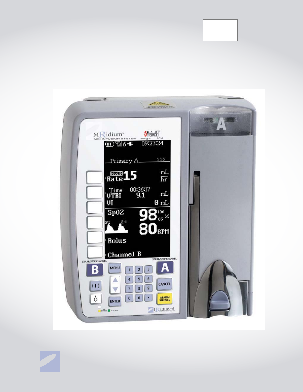
1.1.1 Front of the Pump ....................................................................1-2
1.1.2 Pump Drive Mechanism .............................................................1-3
1.1.3 Back of the Pump .....................................................................1-4
1.1.4 1120 MRI Power Supply ............................................................ 1-5
1.1.5 Front of the Remote Display/Charger ..........................................1-6
1.1.6 Back of the Remote Display/Charger...........................................1-7
1.2 Controls...........................................................................................1-8
1.2.1 Front Panel Control Keys ...........................................................1-8
1.3 Pump Preparation for Use................................................................. 1-10
1.3.1 Administration Sets ................................................................1-11
1.3.2 Artifacts................................................................................1-11
1.4 Display .......................................................................................... 1-13
1.4.1 Informational Display.............................................................. 1-17
1.4.2 User message area................................................................. 1-17
1.4.3 Infusion Parameter Setup Display.............................................1-17
1.4.4 Secondary.............................................................................1-18
1.4.5 Bolus....................................................................................1-18
1.4.6 Special Features Setup Menu ................................................... 1-19
1.5 User Interface.................................................................................1-19
1.6 System Self Test .............................................................................1-19
1.7 Maintenance and Operator Verification ...............................................1-19
1.8 Cleaning Instructions .......................................................................1-20
2.0 Installation.....................................................................................2-1
2.1 Introduction......................................................................................2-1
2.2 Unpacking the Pump..........................................................................2-1
2.3 Unpacking Remote Display/Charger .....................................................2-1
2.4 Unpacking 3861 Channel B SideCar .....................................................2-2
2.5 Preparing the Pump for Use ................................................................2-2
2.5.1 Installing Battery......................................................................2-2
2.5.2 Installing Optional Pulse Oximeter Sensor....................................2-2
2.5.3 Removing The Pulse Oximeter Sensor .........................................2-2
2.6 Mounting on I.V. Pole......................................................................... 2-2
2.7 Operational Checkout of the Pump.......................................................2-2
2.7.1 Determining the current IV Pump Software revision level:..............2-3
2.8 Pump Storage...................................................................................2-3
2.9 Remote Display Installation ................................................................2-3
2.9.1 Charging Battery with the Remote. .............................................2-4
2.10 Language Options..............................................................................2-5
2.11 Product Structure ..............................................................................2-5
i

3.0 I.V. Set Preparation for Use............................................................3-1
3.1 Precautions.......................................................................................3-1
3.2 I.V. Set Priming ................................................................................3-2
3.2.1 I.V. Administration Set 1056 Priming ..........................................3-2
3.2.2 I.V. ByPass Set 1055 Priming.....................................................3-2
3.2.3 I.V. Syringe Adapter Set 1057 Priming ........................................3-2
3.2.4 I.V. Extension Set 1058 Priming .................................................3-3
3.3 I.V. Set Insertion and Removal............................................................3-4
3.3.1 Administration Set Insertion ......................................................3-4
3.3.2 Administration Set Removal.......................................................3-4
4.0 Primary Configuration ....................................................................4-1
4.0.1 Programming a Basic Infusion....................................................4-1
4.0.2 Editing the Infusion Program......................................................4-2
4.0.3 Canceling/Pausing an Infusion....................................................4-2
4.0.4 KVO (Keep Vein Open) - Infusion Complete..................................4-3
4.0.5 Volume Infused........................................................................4-3
4.0.6 Pump Shut Down......................................................................4-3
4.0.7 Restoring an Infusion following Pump Power Down........................4-3
4.1 Dual Channel Infusion........................................................................4-4
4.1.1 Dual Channel Infusion Setup......................................................4-4
4.1.2 Single Channel/Dual Display Setup .............................................4-4
4.2 Secondary (“Piggyback”) Infusion Configuration ....................................4-5
4.2.1 Priming a Secondary Administration Set ......................................4-6
4.2.2 Secondary Infusion Setup..........................................................4-6
4.2.3 Programming a Secondary Infusion.............................................4-7
4.2.4 Viewing Primary Settings during a Secondary Infusion...................4-8
4.2.5 Changing Primary Settings during a Secondary Infusion.................4-8
4.2.6 Stopping a Secondary Infusion and Returning to Primary Infusion...4-8
4.2.7 Dual Channel Operation.............................................................4-8
4.3 Bolus Delivery...................................................................................4-9
4.3.1 Bolus Setup and Start ...............................................................4-9
4.3.2 Stopping Bolus Rate Dose........................................................4-10
4.3.3 Restoring Bolus Dose. .............................................................4-10
4.4 Channel B ...................................................................................... 4-11
4.4.1 Attaching the Channel B SideCar .............................................. 4-11
4.4.2 Detaching the Channel B SideCar.............................................. 4-11
4.5 Special Features Menu .....................................................................4-12
4.5.1 Dose Rate Calculation .............................................................4-14
4.5.2 Alarm Volume........................................................................ 4-21
4.5.3 KVO Rate ..............................................................................4-22
4.5.4 Occlusion Limits ..................................................................... 4-23
4.5.5 Lock Keys..............................................................................4-24
4.5.6 NEXT MENU key .....................................................................4-24
4.5.7 Radio Channel menu...............................................................4-24
4.5.8 Exiting the Special Features Menu.............................................4-25
4.6 Air Bubble Detection and Reset. ........................................................4-25
4.7 Data Retention................................................................................4-25
5.0 Alarms............................................................................................5-1
5.1 Introduction......................................................................................5-1
5.2 User Messages..................................................................................5-1
5.3 Responding to an Alarm .....................................................................5-1
5.4 Remote Alarms .................................................................................5-2
ii

6.0 Battery Operation...........................................................................6-1
6.1 Introduction......................................................................................6-1
6.2 Inserting the Battery Pack ..................................................................6-1
6.3 Charging the Battery Pack ..................................................................6-1
6.4 Removing the Battery Pack.................................................................6-2
6.5 Testing the Battery Pack.....................................................................6-2
6.6 Battery Charge Indicator ....................................................................6-3
6.7 Battery Low Indication .......................................................................6-3
6.8 Battery Power Gauge .........................................................................6-4
6.9 Battery Care and Maintenance: ...........................................................6-4
6.9.1 Introduction.............................................................................6-4
6.9.2 1133 Battery Pack Maintenance Checkout Procedure .....................6-4
6.10 Battery Pack Replacement ..................................................................6-4
6.11 Battery Pack Related Precautions.........................................................6-5
7.0 Introduction, Pulse Oximeter, 3860+ .............................................7-1
7.0.1 User Warnings and Precautions ..................................................7-1
7.1 Installation.......................................................................................7-3
7.2 Symbols, Displays, and Controls..........................................................7-4
7.2.1 SpO2 Symbols .........................................................................7-4
7.2.2 Displays..................................................................................7-5
7.3 Operator Verification..........................................................................7-7
7.4 Operating the 3860+ Pulse Oximeter ...................................................7-7
7.4.1 Probe Set-up and Use ...............................................................7-8
7.4.2 Applying the Model 1170 Fiberoptic SpO2 Sensor..........................7-8
7.4.3 Verifying Operation of the Model 1170 Fiber Optic Sensor ............ 7-11
7.5 Probe Cleaning................................................................................7-11
7.5.1 Cleaning the Model 1170 Fiberoptic Sensor and 1171 Sensor Grips 7-11
7.6 SpO2 Alarms and Alerts ...................................................................7-11
7.6.1 Patient and Equipment-Related Alarms...................................... 7-11
7.6.2 Watchdog Alarms ...................................................................7-11
7.6.3 Reviewing, Setting, or Changing Volumes and Alarm Limits..........7-12
7.7 SpO2 Menu Choices .........................................................................7-12
7.8 SpO2 Troubleshooting...................................................................... 7-13
7.9 SpO2 Parts and Accessories .............................................................. 7-15
7.10 SpO2 Testing Summary.................................................................... 7-16
7.11 Specifications..................................................................................7-17
7.12 The Masimo Set® Principles of Operation............................................7-18
8.0 Dose Error Reduction System .........................................................8-1
8.1 Introduction: ....................................................................................8-1
8.2 DERS Installation ..............................................................................8-1
8.3 DERS FEATURES AND DEFINITIONS.....................................................8-2
8.4 DERS RELATED ALERT AND USER PROMPT MESSAGES ...........................8-3
8.4.1 ALERT / PROMPT - MESSAGES, TYPE, CAUSE AND RESOLUTION .....8-4
8.5 DERS Indicators / Status....................................................................8-6
8.6 SETTING UP A DERS PRIMARY INFUSION..............................................8-7
8.6.1 SETTING UP A DERS PRIMARY INFUSION.....................................8-7
8.6.2 Adjusting a Dose or the VTBI During an Infusion.........................8-14
8.6.3 SETTING UP A DERS BOLUS.....................................................8-15
8.6.4 REPEATING A BOLUS DOSE .....................................................8-19
8.6.5 Canceling Bolus Delivery .........................................................8-20
8.6.6 DUAL CHANNEL DERS INFUSION ..............................................8-21
8.6.7 DUAL CHANNEL BOLUS DELIVERY.............................................8-23
iii

Specifications..........................................................................................A-1
Repair .....................................................................................................B-1
Warranty information..............................................................................C-1
Manufacturers Technical declaration ...................................................... D-1
IV Sets and Accessories...........................................................................E-1
Troubleshooting ......................................................................................F-1
1119 I.V. Pole Assemblies and Parts descriptions..................................G-13
Trumpet and start up curves................................................................... H-1
Appendix A: Specifications ......................................................................A-1
Appendix B: Repair..................................................................................B-1
Appendix C: Warranty information...........................................................C-1
Appendix D: Manufacturers Technical Declaration .................................. D-1
Appendix E: Accessories..........................................................................E-1
Appendix F: Troubleshooting ...................................................................F-1
Appendix G: 1119 I.V. Pole Assemblies and Parts Descriptions............... G-1
Appendix H: Trumpet and start up curves............................................... H-1
Appendix I: 1145 Dose Error Reduction System....................................... I-1
iv

FIGURES
Figure Page
1-1 Front of Pump...................................................................................1-2
1-2 Pump Drive Door Open.......................................................................1-3
1-3 Bac k of Pump....................................................................................1-4
1-4 Model 1120 MRI Power Supply ............................................................1-5
1-5 Front of 3865 Remote Display/Charger.................................................1-6
1-6 Bac k of 38 65 Remote Display/Charger..................................................1-7
1-7 Front Panel Control Keys ....................................................................1-8
1-8 Setup Display Screens......................................................................1-13
1-9 Running Screens .............................................................................1-15
1-10 Special Features Setup Menu ............................................................ 1-18
3-1 Free Flow Preventer...........................................................................3-1
3-2 Roller and Slide Clamps......................................................................3-1
3-3 IV Set Installation .............................................................................3-5
4-1 Primary Pump Setup Screen................................................................4-1
4-2 Dual Infusion Display.........................................................................4-5
4-3 Secondary Infusion Set-up and Programming Screen .............................4-7
4-4 Bo lus Setup Displ a ys..........................................................................4-9
4-5 Attaching Channel B “SideCar” .......................................................... 4-11
4-6 Special Features Menu .....................................................................4-12
4-7 Dose Rate Calculation Menu..............................................................4-14
4-8 Primary Screen with Dose Rate Displayed...........................................4-17
4-9 Alarm Volume Adjustment Screen......................................................4-21
4-10 KVO Rate Screen.............................................................................4-23
4-11 Set Comm Channel Displays ............................................................. 4-25
5-1 Alarm Display in User Message Area.....................................................5-2
6-1 Battery Installation............................................................................6-1
6-2 Battery Removal ...............................................................................6-2
6-3 Battery Test......................................................................................6-3
7-1 3860+ Display w/SpO2 ......................................................................7-4
7-2 C onnecting the 117 0 Fibe roptic Probe ..................................................7-9
7-3 Applying the 1170 SpO2 Sensor ........................................................ 7-10
7-4 Saturation Charting. ........................................................................7-19
Table Page
5-1 Alarm , Alert and User Prompt Messages ...............................................5-3
7-1 SpO
Alarm Limits.............................................................................7-8
2
v

General Information
This document provides the following directions for use:
• Single channel pump that provides a full range of features in a compact,
easy to use, linear peristaltic pump.
• Dual channel pump offers the same features while providing two
independent infusion pumps in one instrument.
• The Remote Display/Charger Unit allows for remote ability to control the
Pump with a total of two channels from outside the MR Scanner.
The system is designed for use in the following patient care areas:
• MRI (0.2 to 3T systems).
• MRI/Recovery.
• Pump operable and safe in up to 1 Tesla (10,000 Gauss) magnetic field.
EMI Statement:
This equipment generates, uses and can radiate radio frequency energy and, if not
installed and used in accordance with the instructions, may cause harmful
interference to other devices in the vicinity. However, there is no guarantee that
interference will not occur in a particular installation. If this equipment does cause
harmful interference to other devices, which can be determined by turning the
equipment off and on, the user is encouraged to try to correct the interference by
one or more of the following measures: 1. Reorient or relocate the receiving device.
2. Increase the separation between the equipment. 3. Connect the equipment into
an outlet on a circuit different from that which the other devices(s) are connected. 4.
Consult the manufacture or field service technician for help.
Mains Disconnection Method:
3860 Pump: Disconnect power cord (1121) from Appliance Inlet on the side of the
MRI power supply unit (1120).
3865 Remote/Charger Unit: Disconnect power cord (1128) from Appliance Inlet on
the rear of the Unit.
Alternate Voltage/Export:
For power cord plug types see local country distributor. Unit shipped in USA with US
3 pin power NEMA plug.
3860 EQUIPMENT CLASSIFICATION
Classification according to IEC 60601-1
According to the type of protection
against electrical shock:
According to the degree of protection
against electrical shock:
According to the type of protection
against harmful ingress of water:
According to the methods of sterilization
or disinfection:
According to the mode of operation Continuous operation
Equipment not suitable for use in the presence of flammable anesthetic mixture with air or
with oxygen or nitrous oxide
Class I equipment and internally powered
Type CF (defibrillator-proof) equipment
Ordinary Equipment. Complies with Section 44.4 of the
Infusion Pump standard, IEC 60601-2-24.
Non-sterilizable. Use of liquid surface disinfects only.
vi

About the Pump: Intended Uses
Indications for Use:
The Iradimed Corporation's MRidium 3860+ MRI Infusion Pump/Monitoring System
is intended for general hospital or clinical use by medical professionals whenever it is
required to infuse patients with subcutaneous, intra-venous or intra-arterial fluids
before, during, or after Magnetic Resonance Imaging (MRI) scans, functioning while
either in a stationary or mobile position. The system is useful in the administration of
fluids requiring precisely controlled infusion rates. The system can operate in either
continuous, intermittent, or bolus delivery mode. The Infusion Pump can be used
inside the MRI room mounted outside the 10,000 Gauss line (1 Tesla line), and with
shielded magnets of field strength of 3.0 Tesla or less. This device is available for
sale only upon the order of a physician or other related licensed medical
professional, and not intended for any home use applications.
The Pulse Oximeter is used to measure, display, and record functional oxygen
saturation of arterial hemoglobin (SpO2) and pulse rate of adult, pediatric, and
infant patients in an MR environment. Testing of the oximeter was performed in MR
conditional environments at 1.5T and 3T. It is indicated for spot checking and/or
continuous monitoring of patients who are well or poorly perfused in the MRI.
This infusion pump is contraindicated for use on the inlet side of Extra Corporeal
Membrane Oxygenation (ECMO) systems where the negative pressure is greater
than -100 mmHg as the high negative pressure can result in uncontrolled fluid flow.
TM
The MRidium
providing the non-magnetic motor power driving the MRidium
unit. This allows the MRidium
material and safely operable in high magnetic fields.
Features include:
• Non-magnetic ultrasonic drive motor.
• Special aluminum RF noise shielding enclosure.
The pump is equipped with a unique battery display that provides the clinician
continuous monitoring of battery capacity available. This information is displayed
when the instrument is turned on.
3860+ Infusion System incorporates a unique ultrasonic motor
TM
TM
3860+ to be constructed with minimal magnetic
3860+ pumping
The Dual Rate Feature allows the pump to administer both primary and secondary
solutions at separate flow rates and volumes. Using this feature the clinician can
select and start a program for secondary delivery. Upon completion of the secondary
dose, the pump can automatically switch over to a primary rate. Both channels of
TM
the MRidium
3860+ can be programmed for primary and secondary operation.
Optional modes are easily accessed with the press of one key.
The Dose Rate Calculator allows the clinician to calculate a dose rate for continuous
infusion given concentration and dosage orders.
The Bolus Dose feature allows the clinician to set up an initial infusion rate for a
specific Bolus volume, automatically followed by a maintenance rate from the same
container.
A 2.4 GHz wireless link allows communication between the infusion pump and
remote display.
Qualified service personnel can configure many features of the pump to meet
specialized needs.
Specific pump menu screens may vary depending on software release being used.
vii

This device is covered under one or more of the following U.S. Patents:
7,267,661 B2, 7,404,809 B2 and International Equivalents
7,553,295, 7,553,882, 8,105,282 B2 and International Equivalents
7,753,882; 8,150,493; 8,690,829; 8,262,642; 8,469,932; 8,105,282; 8,500,694
EP1530440; 1802362; 4597970; 5001845 International Patents
Other U.S. and International patents pending.
Possession or purchase of this device does not convey any express or implied license
to use the device with unauthorized infusion sets, sensors or cables which would,
alone, or in combination with this device, fall within the scope of one or more of the
patents relating to this device.
Masimo
®
, Masimo SET®, Signal Extraction Technology® and Signal IQTM are
trademarks or registered trademarks of Masimo Corporation.
Warnings/Precautions
Federal Law in the U.S.A. restricts this device to sale by or on the order of a
physician.
This device is intended for use by trained medical professionals only.
Refer all service to Iradimed Corporation Authorized Service R epresentatives.
The 3860 Pump has been specifically designed for operation inside an MRI Magnet
Room, and is designed to operate normally in the presence of most frequently
encountered electromagnetic interference in the MRI environment. Under extreme
levels of interference, such as in close proximity to an electrosurgical generator,
cellular telephone or a 2 way radio normal pump operation may be interrupted.
Avoid use of this pump under these conditions.
Use only MRI-compatible patient access devices (e.g. needles, luer-ports, etc.) to
prevent any possible RF current from reaching the patient's skin.
The Remote Display Charger is intended for use in the MRI control room. Do not
operate the 3865 Remote Display/Charger inside the MRI Magnet Room.
For safe operation, use only Iradimed Corporation recommended MRI-compatible or
MRI-safe accessories.
The MRI pump must be mounted securely when used in the MRI scan room. Always
securely mount the pump using it’s integral pole mount clamp or other mechanical
fixing means.
Always secure the I.V. Pole wheel locks after positioning within the MRI Magnet
Room.
Avoid placing the I.V. Set adjacent to any electrical conductor within the MRI bore,
which can become heated during MRI scans.
The Alarm Sound Volume is adjustable for various clinical environments. Ensure the
alarm sound level is appropriate for the use environment in the MRI so that it can be
heard above the ambient noise level, especially during scanning.
Product damage may occur unless proper care is exercised during unpacking and
installation. Do not use the pump if it appears damaged in any way. The battery
should be charged before use.
Battery may not be fully charged upon receipt. Connect pump to AC power for at
least nine (9) hours before placing the pump into use.
Always connect the infusion pump power supply or Remote Display/Charger to a
properly grounded 3-wire power receptacle. Never use power extension cords. If the
quality of the earth grounding is in question, use battery power for the infusion
pump.
This equipment is not suitable for use in the presence of flammable anesthetic or
other gases. Do not use this system in the presences of flammable gases.
viii

Precautions/Continued
Arrange tubing, cords and cables to minimize the risk of patient or other equipment
entanglement.
The pump is not intended for high pressure, high viscosity radiological contrast
agents.
To avoid patient injury, always respond to Pump or Remote Display/Charger alarms
immediately.
Never leave the patient with the Pump stopped if the infusion has not been
completed.
To prevent injury, avoid placement of an y NIBP cuff on the limb receiving the I.V.
therapy.
The Pump contains materials which must be recycled, or disposed of properly. For
proper disposal methods, contact your local sales representative or distributor.
Hospital personnel must ensure the compatibility of the drugs as well as the
performance of each pump as part of the overall infusion. Potential hazards such as
drug interactions, inaccurate delivery rates, inaccurate pressure alarms and
nuisance alarms may arise from other incompatibilities.
MRI pump uses medical grade silicone rubber and PVC tubing. Do not infuse
pharmaceuticals or solutions that are incompatible with these materials. Drugs not
compatible with silicone rubber or PVC plastics, or drugs not stable under infusion
conditions should not be used with this system.
Consult the drug labeling to confirm drug compatibility, concentr ation, delivery r ates
and volumes are suitable for concurrent delivery, or piggyback delivery (secondary
followed automatically by primary).
Simultaneously infusing with more than one pump into one patient line may
significantly affect the infusion rate of at least one of the pumps.
Hyberbaric Chamber Operation: The MRidium system is not certified for use in
oxygen enriched environments. It is not intended for use in this environment.
Equipment use outside it’s specified environmental conditions can affect infusion
accuracy.
WARNING: This product may contain a chemical known to the State of California
(U.S.A.) to cause cancer, or birth defects or other reproductive harm.
Pump Related Warnings/Precautions
This pump is designed to stop fluid flow under alarm conditions. Periodic patient
monitoring must be performed to ensure the infusion is proceeding as expected.
Immediately respond to a “Close Door” alarm due to imminent lapse in infusion
therapy.
Immediately respond to the “Check Door” alarm as this indicates possible Free-Flow
of IV Fluids.
Dropping, or a severe shock to the pump, could result in damage and resultant
pump inaccuracy. Refer the pump to qualified service personnel for proper checkout
if either of these conditions occur.
Do not place the pump into use if it fails any of the Power On Self Tests.
Always verify flow rate, VTBI (V olume to be Infused) and/or dose drug entries before
starting infusion.
When opening the door, always check that the free flow preventer (black slide
clamp) is fully pulled outward to the shut off position.
ix

Pump Related Warnings/Precautions (Continued)
If questionable Pump operation is observed, or if a System Failure occurs (i.e. an
unexplained continuous audible alarm with no displayed values), discontinue use of
the Pump and refer it to qualified service personnel.
Although unlikely, failure of certain rugged mechanical components, such as the
free-flow prevention mechanism could cause fluid delivery limited to the contents of
the fluid container. The maximum volume that may be infused under a single fault
condition is 0.1 mL. Single fault failure of any electronic or motor control component
would result in less than 0.3 mL of unexpected fluid delivery.
A small amount of fluid is expelled from the set (less than 0.05 mL) under worse
case conditions when the mechanical drive advances to Index each time the pump
latch is opened and closed with a set loaded. If potent drugs are being used, take
appropriate action to guard against overmedication of the patient.
Always set the occlusion pressure alarm limit at the minimum level required for the
prescribed fluid therapy.
Whenever closing the Pump Door, check to make sure that nothing interferes with
the pumping mechanism.
During a running infusion, each interruption and re-start of the infusion can add
approximately 0.05 mL of delivered fluid to the indicated Volume Infused.
There are dangerous voltages present on internal components that may cause
severe shock or death upon contact. Never open the pump casing, it’s power supply ,
or the Remote/Charger when connected to AC Mains power. Disconnect from AC
power and remove battery pack prior to servicing or cleaning.
Do not operate the pump on patients with the battery removed (pump will stop and
not alarm during AC power loss without battery installed). Use of a properly
maintained and charged battery will allow proper operation. Do not touch battery
connector pins and patient simultaneously.
If the Low Battery alarm sounds, connect the pump with its power supply to AC
power immediately.
Replace blown fuses on the 1120 Pump MRI power supply or Remote Display/
Charger with fuses of the same type and rating only, or a fire hazard could exist.
Never use sharp objects (paper clips, needles, etc.) to clean any part of the pump.
Keep the pump door latch securely closed when the pump is not in use. This will
avoid door latch damage.
Do not sterilize the pump or any component by heat, steam, ethylene oxide (ETO),
or radiation.
The screen displays the VTBI (Volume to be Infused) in whole integers above 99.9.
Any fraction of a milliliter delivered is not displayed, but is retained in memory.
To avoid damage to the I.V. Pump and Pole, always move the I.V. Pole separately
from the patient trolley to prevent accidental entanglement.
The pump body is made of aluminum and is non-magnetic. However, when moving
the pump within high magnetic fields (>2000 gauss) one might notice Eddy Current
effects. These are forces generated in the aluminum which resists motion through
the intense magnetic field. Such effects are normal and present no risk of free
magnetic movement of the unit.
Sensors detect open or poorly shut door clamp and incompletely closed IV Set free
flow preventer clamp, generating a “Check Door” alert. Immediate attention should
be given to possible free flow.
x

Set Related Warnings/Precautions
Always use aseptic techniques. Patient infection could result from mishandled or
non-sterile assemblies.
Use only Iradimed Corporation MRidium
of other sets will cause improper pump operation resulting in inaccurate fluid
TM
delivery. MRidium
with the MRidium
1000 Series administration sets are only intended to be used
TM
Pump.
All infusion administration sets are supplied sterile and are single use only. Do not
sterilize or re-use. Patient infection or inaccurate flowrate could result.
Prior to use of any Infusion Set, examine the pouch and inspect for damage that
could compromise sterility. If the pouch or Set is damaged, discard and use another
Set.
Administration sets should be changed per the Center for Disease Control (CDC)
guidelines or healthcare provider policy . Disc ard after use. Design use life of I.V. sets
is six (6) hours maximum.
Disconnect the I.V. line from the patient before starting the priming procedure.
Prepare the primary solution container in accordance with the manufacturer’s
instructions.
The use of positive displacement infusion devices ported together with gravity flow
infusion systems into a common I.V. site may impede the flow of the gravity flow
system and affect their performance. Hospital personnel must ensure that the
performance of the common I.V. site is satisfactory under these conditions.
Interconnection with I.V. sets with small inner diameter may affect pump accuracy at
high flow rates. Avoid interconnection with small bore diameter I.V. sets (less than
0.050 inch (1.25mm) I.V. tubing) if high flow rates are used.
A kinked or occluded I.V. line could cause the pump to operate abnormally and affect
the accuracy of the infusion. Before operating this system, verify that the I.V. line is
not kinked or occluded.
To avoid nuisance alarms, confirm that the fluid source is positioned higher than the
pump.
Setting the primary rate greater than the secondary rate will result in a more rapid
infusion of any residual secondary drug remaining in the line, the administration set,
and fluid container.
When performing a secondary infusion:
• Secondary solution container must be higher than the primary
solution container.
• The Secondary VTBI (Volume to be Infused) setting must be
equal to the volume in the secondary container. This requires
consideration of such variables as factory overfill, medication
additions, etc. Underestimating the volume will cause the
remaining secondary solution to be infused at the primary rate;
overestimating will result in the primary solution being infused at
the secondary rate. Multiple doses from a single container are
not possible.
Air bubbles may form distal to the pump as a result of normal out-gassing of
dissolved air in the fluid. This may occur if a chilled solution is being used, if the
pump is mounted significantly above the patient, or with certain fluids known to
routinely outgas. In these cases, an air eliminating filter may be required.
During a prolonged infusion, routinely inspect I.V. Set, access device and patient line
assemblies for proper attachment and orientation.
TM
1000 Series administration sets. The use
xi

Set Related Warnings/Precautions (Continued)
Variations of head height, back pressure, selected catheter type, or any combination
of these may affect rate accuracy. Factors that can influence back pressure are: I.V.
set configuration, I.V. solution viscosity and I.V. solution temperature. Back pressure
may also be affected by catheter type.
The use of pumping infusion devices ported together with gravity flow infusion
systems into a common IV site (primary IV set with secondary IV lines) can affect
the accuracy of the gravity flow systems, and result in unintended flow rates from
these gravity systems. Always ensure the common IV site is acceptable for use
under these conditions.
Reference to specific drugs and default parameters are provided for the user’s
convenience. Always refer to the specific drug product labeling for information
concerning appropriate administration techniques and dosages.
Battery Pack Related Warnings/Precautions
The 1133 Battery Pack contains several lithium-polymer cells and an integral safety
circuit. As these cells age, they can expand due to internal gas release, which is
anticipated for this type of cell. However, if excessive expansion occurs, this can
result in the battery case expanding (swelling), and possibly cause failure of the
battery case, cells, or safety circuit. If this is observed, remove the Battery Pack
from use and replace it as soon as possible.
The 1133 Battery Pack contains protective circuitry to prevent catastrophic battery
failure. If the Battery pack is damaged, this protective circuitry may not prevent
battery failure. Remove the Battery P ack fr om use if the Pack becomes damaged, or
the potential for Battery Pack damage is suspected.
Do not use a damaged or swollen 1133 Battery Pack.
Avoid damage to the 1133 Battery Pack by impact, dropping, overheating, or
mechanical abuse. Never compress, drop, shock, or strike the 1133 Battery Pa ck.
Never use objects that could puncture the internal battery cells. Any of these
actions can cause the battery cells to heat, smoke, or cause catastrophic battery
failure, which could result in fire.
Do not attempt to disassemble the 1133 Battery Pack. Damage caused by
disassembly or tool use can result in catastrophic battery failure, which could result
in fire.
If the 1133 Battery Pack case begins to expand and/or swell, discontinue battery
charging and use immediately, and replace the Battery Pack. Continued charging
will cause further Battery Pack case expansion, with possible battery case fracture,
and potential electrolyte leakage.
If the 1133 Battery Pack becomes damaged, avoid contact with the battery cell
electrolyte. If the electrolyte contacts the skin or eyes, seek medical attention
immediately.
If the 1133 Battery Pack shows sign of the battery case expanding (swelling),
remove the Battery Pack from use and replace it as soon as possible. In extreme
conditions, this swelling can cause the 1133 Battery Pack to become jammed or
stuck within the 3860 Pump or 3865 Remote Display, and/or cause the Battery Pack
plastic case to burst open. If this occurs, do not use tools that could cause damage
to the internal battery cells. Refer to the 1125 Service Manual for removal under
these conditions.
Under no circumstances should Battery Packs or the internal cells be incinerated as
this can cause an explosion.
xii

Pulse Oximeter Related Warnings/Precautions
USE ONLY Recommended SpO2 Fiberoptic Sensors (Sensors containing electrical
conductors will cause patient burns). Do not use cables or sensors that contain
conductive wires.
This device is intended only as an adjunct device in patient assessment. It must be
used in conjunction with other methods of assessing clinical signs and symptoms.
Iradimed SpO
cable / male connector on pump) than that found with other non-MRI pulse
oximeters. This is done to help prevent improper sensor connection to the pump.
Use only recommended pulse oximeter sensors. These sensors are manufactured to
meet the accuracy specifications for Iradimed Corporation’s pulse oximeters. Using
other manufacturers’ sensors can result in improper pulse oximeter performance.
The fiberoptic cable for this device is extremely sensitive and must be handled with
caution at all times. DO NOT use a damaged sensor.
Refer to the User Warnings and Precautions area in Section 7 (Pulse Oximeter) for
additional Pulse Oximeter related warnings and precautions.
sensors are reverse gender connectors (female connector on sensor
2
xiii

User Responsibility
This product will perform in conformity with the description contained in this users
manual and accompanying labels, inserts, etc., when assembled, operated,
maintained and repaired in accordance with the instructions provided. This product
must be checked and calibrated periodically. A malfunctioning product should not be
used. Parts that are broken, missing, plainly worn, distorted or contaminated should
be replaced immediately. Should such repair or replacement become necessary,
refer unit to Iradimed Corporation qualified service personnel. This product or any of
its parts should not be repaired other than in accordance with written instructions
provided by the manufacturer, or altered without written approval of Iradimed
Corporation. The user of the product has the sole responsibility for any malfunction
which results from improper use, faulty maintenance, improper repair, damage or
alteration by anyone other than Iradimed Corporation or Iradimed Corporation
authorized service personnel.
Using This Manual
Read this manual completely before attempting to use the pump.
Warning, Cautions and Notes. This manual contains three levels of precautionary
information.
•A Warning alerts the user that there is a possibility of injury or death to a
human being.
•A Caution alerts the user that there is a possibility of damage to
equipment.
•A Note contains essential information deemed especially important by
Iradimed Corporation.
Definitions
Channel A The designation for the first infusion channel. All pumps contain at
least one linear peristaltic pump head for one infusion line.
Channel B The designation for the second infusion channel. The second infusion
pump module is optional and some pumps may not contain it.
hr. hour.
KVO Keep-Vein-Open.
mL milliliter.
Primary Main Infusant for the prescribed I.V. therapy. The infusion settings
that are implemented after any secondary infusion sequence is
complete.
Rate Infusion rate in mL / hr.
Secondary The first infusion settings to be implemented in an infusion sequence
when more than one infusion is delivered with the same pump
channel, sometimes referred to as “piggyback.”
VI Volume Infused in mL.
VTBI Volume To Be Infused in mL.
%SpO
2
Percent of Oxygen (pulse) Saturation.
xiv

Symbols
ISO 8536-8-IS-P
Attention: Consult Accompanying
Documents, or alternately, Caution
Defibrillator proof
Type CF Applied Part
Date of Manufacture
Indicates that the device conforms
to the Medical Device Directive
Direct Current
Indicates Infusion Sets comply with
requirements specified in ISO 85368 (Infusion Equipment with pressure
infusion apparatus up to a maximum
of 200 kPa).
Drops per milliliter specification for
I.V. Set is identified on Drop Symbol
Appropriate for use in MR
environment
MR Conditional. Only appropriate
for use in MR environment with
manufacturer’s defined
restrictions.
MR Unsafe. Not appropriate for
use in MR environment (i.e. inside
the MR magnet room)
Single Use Only
Product Serial Number
Alternating Current
Do not Resterilize
Lot or batch code for I.V. Set will be
identified near Lot Symbol
Approximate Set priming volume
Main Battery Capacity . (X inside Icon
denotes no battery installed.)
AC Power is connected to 100-240
VAC
Product Part Number
Expiration date for I.V set will be
identified near hour glass symbol
Denotes I.V. Set was sterilized
with Irradiation
Contains Lithium. Requires proper
disposal/recycling of this material.
Secondary Infusion Mode
Volume to be Infused
Caution: Federal (U.S.A.) law
restricts this device to sale by or on
the order of a physician
Maximum rated load is 20 Kg.
Power On, or On
Power Off, or Off
Volume Infused
Both Input/output connection.
Allows data communication.
xv

Do not discard. Contact recycler for
proper disposal
Input Connection Only
Output Connection Only
EC Authorized Representative
Percent of Oxygen (pulse)
Saturation
Radio-Frequency transmission
source
Storage Temperature Range
BPM
2.4 GHz Radio is communicating.
Pulse Rate in Beats/Minute
Pulse Detected
Telecommunications Alert Symbol
- Class 2 (European Union
Countries Only)
This product has been certified to
UL60601-1 and applicable Particular
Standard IEC 60601-2-24, for which
the product has been found to
comply by Intertek.
Spare Battery Capacity. (X inside
Icon denotes no battery installed.)
Refer to operating instructions
for important safety information.
STBY
2.4 GHz Radio Antenna
Infusion has been paused.
Press start to resume infusion
xvi

>>>
Alternating symbols indicate
Channel A is infusing
Sterile Fluid Path Do not use if package is
Keep equipment below this line
on the 1119 IV Pole.
<<<
Alternating symbols indicate
Channel B is infusing
damaged
Replace fuse with 1 Amp, 3AG,
250V time delay (Slow Blow)
fuse.
xvii

xviii

SECTION 1
INTRODUCTION
1.0 Introduction. The MRidiumTM 3860/3860+ MRI Infusion/Monitor System is
intended for patients that require medications and/or fluids during an MRI scan. This
pump is designed to provide infusion therapy at all stages of the MRI procedure. This
system is for use by trained medical personnel only and is not intended for long term
patient care outside of an MRI environment.
This system provides the following features:
• Continuous Infusion, Dose Rate Calculation Program and Automatic Bolus.
• Automatic free-flow protection for the I.V. line.
• Up to two channel fluid delivery, each with separate primary/secondary
programmable rate and VTBI, into single or separate IV lines.
• Rechargeable long life battery. Lasts up to 12 hours at 125 mL/hr.
• Status indicator light above door (Red for Alarm, Green for Infusing).
• Soft keys to program various functions.
• Large LCD display screen.
• Up and Down arrow control keys and 10 Key numeric Keypad to change
numeric values quickly and easily.
• Handle for easy portability, weighs less than 11.5 pounds.
• I/O port for Service related functions.
• Optional second channel with the addition of the 3861 SideCar
• Optional remote control with the additional 3865 Remote Display/Charger.
• Optional Dose Error Reduction System with dedicated drug library card.
• Memory card slot for easy upgrades.
• On-Board Masimo SpO
Monitor (3860+ only).
2
• Expanded Infusion Rate Range from 0.1 to 1400 ML/Hr.
TM
.
CAUTION: Handle the MRidium
additional accessories with care. If it should be dropped or severely jarred, it
should be immediately taken out of service and inspected by a qualified biomedical
technician.
1.1 Product Description.
designed for operation in the MRI environment and may be used on the patient near
the MRI magnet (up to the 1.0 Tesla or 10,000 Gauss Line). Operating on battery
power, when fully charged this system will provide up to 12 hours of operation at an
infusion rate of up to 125 mL/hr and at least four (4) hours at r ates up to 999 mL/hr.
The MRidium Wireless Remote Display allows for remote ability to control the Model
3860 MRidium MRI Infusion/Monitor Pump with a total of two channels from outside
the MR Scanner. It utilizes the same user interface as the 3860 infusion pump and
will allow adjustment of all pump parameters, rates, titration, volume to be infused,
starts, stops, and resetting alarms. The large clear display shows all pump
information at your desk top from the control room. The Wireless remote also acts
as a charger for a backup or spare battery pack for the 3860 MRidium MRI Infusion/
Monitor Pump. It utilizes a wireless link at 2.4 GHz for easy installation with no
image artifacts.
NOTE: The 3860/3860+ pumps will only communicate with 3865 wireless
Remote/Display units.
NOTE: The Remote Display/Charger only operates on AC Mains Power. This unit
does not operate on battery power. This unit does not sound a Low Battery alarm
for the Spare Battery being charged.
The MRidium
TM
3860/3860+ MRI Infusion/Monitor Pump and
TM
3860 MRI Infusion/Monitor System is
1-1

1.1.1 Front of the Pump. See Figure 1-1 for the location of the major components
on the front of the pump.
a. Handle. Located on the top of the pump, the handle provides for easy
transportation of the pump from location to another.
b. Main Display. Provides a visual display of all the parameters and
features of the pump.
c. Run/Alarm Lamp. Provides a visual display of the pumps operating
condition.
d. Battery. Located behind a door on the back of the pump, the battery
provides for power in the absence of a hospital grade AC Mains outlet.
e. Pump Area EZ-Latch Door. Pressing down on this button and lifting
this handle unlatches the door protecting the pumping mechanism and
infusion line.
f. Main Control Keypad. Provides control of the various features of the
pump including 10 key numeric keypad for entering parameter values
quickly and easily.
g. Soft keys. Provides a way to adjust the configuration of the pump.
h. AC Power/Battery Charge LED. Provides indication that MRI power
supply is connected and AC power is applied to Charge the pump
battery.
Figure 1-1. Front of Pump
1-2

1.1.2 Pump Drive Mechanism. See Figure 1-2 for location of the major
components of the infusion system pump drive mechanism.
Figure 1-2. Pump Drive Door Open
a. Upper and Lower I.V. Set Snap-In Port. Provides for a secure
mounting of the I.V. set for infusion.
b. Linear Peristaltic Pump Drive Mechanism. Provides for the positive
movement of fluids through the infusion line.
c. Bubble Detector. Provides for the detection of air bubbles in the
infusion line.
d. Free-Flow Detector Switch. Located internally in the pump’s lower
snap-in port the IV Set Free-Flow Detector Switch detects when IV set
is properly installed and functioning.
e. Inlet and Outlet Pressure Sensors. Provide infusion line pressure
measurements for pressure monitoring and alarms.
TM
NOTE: After attachment of the 3861 Sidecar
TM
the operation of Channel B Sidecar
pump drive mechanism is identical to the
module (Refer to Section 4.6),
main pump drive. The only difference is that the Channel B door opens to the left
side, which is opposite that of the main pump door.
1-3

1.1.3 Back of the Pump. See Figure 1-3 for the location of the major components
on the back of the pump.
a. Handle. Provides for easy transportation of the pump from location to
another.
b. Optional Secondary Pump Drive Electrical Connector. Provides for
the addition of a Channel B pump mechanism.
c. I.V. Pole Clamp. Provides a secure mounting of the pump to the IV
pole. Rotate knob clockwise to secure pump to the IV pole.
d. Audible Speaker. Provides the audible sounds for alarms and alerts.
e. 2.4 GHz Antenna and Connector. Used to connect Antenna for
Remote Display/Charger 2.4 GHz wireless interface.
f. Power Input. Provides for connection to the AC Power Adapter to run
the pump on hospital grade AC Mains power. Connect only model
1120 MRI Power Supply.
Figure 1-3. Back of Pump
1-4

g. I/O Port. Provides a connection for retrieving the pump’s infusion data
from memory. Connect only 60601-1 compliant computer for
History Log download.
WARNING: Serial I/O Port is not PC-compatible computer format (Pin # 8 is
connected to the +5 volt supply). Refer to the Service Manual for History Log data
download instructions. Do not communicate through this port during patient use.
h. Memory Port. Provides for field update of system software or
receptacle for retaining the optional DERS Drug Library Card (Refer to
Section 8). Use only AM04 update card, AM04DERS update or
Iradimed Corporation recommended Media/Memory cards.
i. SpO
Iradimed SpO
Series SpO
j. Battery Compartment. Provides a safe and secure location for the
pump’s battery. Use only Iradimed model 1133 Battery Pack.
Sensor Port. (3860+ only) Provides the connection for the
2
Fiber Optic Sensor. Use only Iradimed model 1170
2
Fiberoptic Sensors.
2
CAUTION: Battery pack is slightly magnetic. Use caution when removing from
pump near strong magnetic fields.
1.1.4
Power Supply.
1120 MRI Power Supply. See Figure 1-4 for information on the pump’s MRI
WARNING: AC Adapter is magnetic. Keep outside the 1,000 Gauss line, or at
least 10 feet (3 meter) from the MRI magnet. Secure with velcro straps provided
to the floor. NEVER Velcro or secure the AC Adapter directly to the pump or I.V.
pole.
Figure 1-4. Model 1120 MRI Power Supply
1-5

1.1.5 Front of the Remote Display/Charger. See Figure 1-5 for the location of the
major components on the front of the 3865 Remote Display/Charger.
a. Antenna. Provides 2.4 GHz bidirectional communication to MRidium
TM
3860 MRI Infusion/Monitor Pump.
b. Main Display. Provides a visual display of all the parameters and
features of the pump.
c. Run/Alarm Lamp. Provides a visual display of the pumps operating
condition.
d. Battery Charger Compartment. Located at the top rear of the
Remote, allows charging of an 1133 Pump Battery when battery is
installed and Remote is connected to AC Mains outlet as indicated by AC
Power/Battery Charge LED (located below the power On/Off keys).
e. Main Control Keypad. Provides control of the various features of the
pump.
f. Soft keys. Provides a way to adjust the configuration of the pump.
g. AC Power/Battery Charge LED. Provides indication that AC power is
applied (Green) or Charging a spare battery (Amber).
h. Memory Port. Located underneath the front panel provides for field
update of system software. Use only AM04 Software Card.
Important: 3865 Remote Display/Charger will only communicate with 3860 or
3860+ pumps. These can be recognized by the 10 digit main control
keypad.
Figure 1-5. Front of 3865 Remote Display/Charger
1-6

1.1.6 Back of the Remote Display/Charger. See Figure 1-6 for the location of the
major components on the back of the 3865 Remote Display/Charger.
a. Audible Speaker. Provides the audible sounds for alarms and alerts.
b. 2.4 GHz Antenna / Connector. Used to connect 2.4 GHz Antenna for
wireless communication with the 3860/3860+ MR IV pump.
c. Power Input. Provides for connection to hospital grade AC Mains
power.
d. Fuse Holder. Provides replaceable 1A 3AG, 250V fuse for the AC Mains
power.
e. Ground Terminal. Used for grounding lug during electrical testing.
f. Battery Charger Compartment. Located at the top rear of the
Remote, allows charging of an 1133 Pump Battery when battery is
installed and Remote is connected to AC Mains outlet as indicated by AC
Power/Battery Charge LED (located below the power On/Off keys).
Remote/Charger is AC powered only and will not run on battery power.
CAUTION: Battery pack is slightly magnetic. Use caution when transferring
battery pack from pump to Remote/Charger near strong magnetic fields.
CAUTION: Gently position 1133 battery pack into charger compartment until
battery pack snaps into position. Do not drop or force the battery pack into the
charger compartment, as this could cause battery pack damage or failure.
Figure 1-6. Back of 3865 Remote Display/Charger
1-7

1.2 Controls. The MRidiumTM 3860 MRI Infusion/Monitor System is controlled
with the use of “soft-touch” control keys. These control k eys are located on the front
panel of both the Pump and Remote Display. These control keys provide for turning
the Pump and Remote Display ON or OFF, starting/stopping Channel’s A and B
infusion sequences, accessing and navigating in operational menus, review of data
and setups, and for silencing any active alarms that may occur.
1.2.1
Front Panel Control Keys. See Figure 1-7 for location of the control keys.
Figure 1-7. Front Panel Control Keys
1-8

START/STOP CHANNEL A. Pressing this control key starts, or
stops, the Channel A infusion sequence.
CANCEL. Pressing the control key returns function to the
previous menu or display with no action.
Up and Down Arrows. Pressing this control key will increase
or decrease the value of the currently selected option. It is also
used for on-screen menu navigation.
MENU. Pressing this control key activates the Main Menu
Display.
ENTER. Pressing this control key will activate, or select, a
menu choice, proceed from one prompt to the next and accept/
store changes.
START/STOP CHANNEL B. If the Channel B option
(SideCar
key starts, or stops, the Channel B infusion sequence.
ALARM SILENCE. Pressing this control key temporarily
silences audible alarms for two (2) minutes and clears alarms
that have been resolved.
TM
Pump mechanism) is installed, pressing this control
( l ) Pressing this control key turns the unit on. When the unit
is on this control key is inactive.
O Pressing and holding this control key for longer than one
(1) second turns the unit off.
Special Function Soft Keys. The six (6) Soft Keys, located to
the left of the pump’s display screen, are used to perform
variable functions depending on the current state of the device.
When active there is a small arrow present to the right of the
key on the pump’s display.
Numeric Key Pad. The numeric keypad can be used to input
values for flow rates or clear a recent entry (“C” key). After
using keys to input correct values, pressing the “ENTER” key
will lock value in place.
1-9

1.3 Pump Preparation for Use.
There are several configurations for starting an infusion with the MRidium
3860+ Infusion Pump. These include the following:
a. Primary Configuration – Refer to Section 4.0. This mode enables an
infusion to be set up with Rate and VTBI only, and is the main screen if the
pump has been turned off for more than one (1) hour. This mode is the
most basic mode of use, as there are no saved infusion settings available
through the “Same Patient” soft key. This mode does not use the DERS
Library Card or the Dose Rate Calculator.
b. Restore Last Infusion settings – Refer to Section 4.0. This mode
restores the last infusion settings after the pump has been powered off for
less than 1 hour. When the pump is powered on, a repeat of the previously
run infusion can be set up quickly. The infusion can be set up to use the
previous infusion’s settings (“Same Patient”) or can be programmed for
new dose information (“New Patient”). This mode requires the setting of
Rate and VTBI only, and does not use the Dose Error Reduction System
(DERS) Library Card or the Dose Rate Calculator.
c. Dual Channel Infusion – Refer to Section 4.1. This mode enables two
infusions to be performed simultaneously on both Channel A and Channel
B (if the optional SideCar is installed – refer to Section 4.4). This would be
used for patients who require two different medications to be delivered,
and a secondary infusion (piggyback) is not used. Both channels are set up
with Rate and VTBI.
d. Secondary Infusion (“piggyback”) – Refer to Section 4.2. This mode
enables two infusions to be performed on one channel (either Channel A or
Channel B). This will have the secondary infusion (piggyback) to deliver
fluid to the patient only. Once the secondary infusion has been delivered,
the primary infusion will resume. Therefore, only delivering one medication
to the patient at a time (which is different than the Dual Channel Infusion,
where both medications are delivered simultaneously).
e. Bolus Delivery – Refer to Section 4.3. This mode enables a bolus of fluid
to be delivered and can be programmed at the start of an infusion, or
added to an infusion in progress on either Channel A or Channel B.
f. Dose Rate Calculator – Refer to Section 4.5.1. This mode is accessed
through the Special Features Menu and is used to calculate the pump
parameters (e.g. flow rate, volume, and/or time) for either Channel A or
Channel B for a dose to be delivered to the patient by entering the Dose
amount, Patient Weight, and Concentration of medication.
g. Dose Rate Calculator with Drug Library – Refer to Section 4.7.1.2.
This mode is accessed through the Special Features Menu and is used to
calculate the volumetric rate for either Channel A or B, and has five (5)
drug options to select from. One of these options, “Drug ?” can be
customized by the user to any name when in the Service Mode and has
user-defined values that serve as a “starting point” for programming the
infusion and can be modified at any time.
1-10

h. Dose Error Reduction System (DERS) Library (optional) – Refer to
Section 8. This mode is optional and is only accessible if a DERS Library
Card has been programmed with the customer’s drug library and installed
into the pump. If a DERS Library Card has been installed, the display will
show “Lib” indicator (refer to Section 8.3.3). If there is not a DERS Library
Card installed, it will show “No Lib” indicator (refer to Section 1.3.1), which
is the normally presented indicator. This mode provides user-programmed
infusion protocols with hard and/or soft entry limits that can be set by the
customer.
WARNING: This pump will stop fluid flow during Alarm Conditions, however,
SpO
related alarms will not stop fluid flow. Periodic patient monitoring must be
2
performed to ensure that the infusion is operating normally.
WARNING: It is the responsibility of hospital personnel to ensure that drugs
used in this system are compatible as well as ensuring the performance of each
pump as part of the overall infusion. Potential hazards include, but are not limited
to, drug interactions, inaccurate delivery rates, inaccur ate pressure alarms and
nuisance alarms.
WARNING: The use of positive displacement infusion devices connected
together with gravity flow infusion systems into a common I.V. site may impede
the flow of common “gravity only” systems and affect their performance. It is the
responsibility of hospital personnel to ensure that the performance of the common
I.V. site is acceptable under the circumstances in which it is being used.
1.3.1 Administration Sets. Use only Iradimed Corporation approved MRidiumTM 1000
series infusion sets. The use of any other set will cause improper pump operation
and will result in inaccurate fluid delivery and risk to the patient.
Before beginning any infusion cycle, verify that the infusion lines are free from kinks
and are loaded correctly on the pump.
Do not reuse any component that is labeled for single use. Discard these items
immediately after use. Patient infection or inaccurate flow rates could result if reused.
1.3.2
being used for the infusion of electrolytes. These currents will vary proportional to
the pump’s infusion rate. Therefore, when an ECG monitoring system is not
functioning under optimal conditions, these currents may appear on the ECG display
screen as artifacts and simulate actual ECG readings. To determine if the ECG
abnormalities are caused by patient condition or the ECG equipment receiving
artifact from the pump, place the infusion pump on HOLD and observe the ECG
signal. If the ECG signal becomes normal, the ECG monitor requires attention as
proper setup of the ECG equipment should remove the pump caused artifact.
Reference the appropriate ECG monitoring system documentation for instructions on
setup and maintenance of the ECG device.
Artifacts. It is normal for this pump to produce non-hazardous currents when
1-11

NOTE: Operating parameters (Power, VTBI, etc.) are retained in memory for one
(1) hour unless all power is lost (no AC and a depleted battery). A “Settings Lost”
message at power up indicates existing operating parameters have been erased,
and the system has reverted back to initial default parameter settings.
The operator may choose “New Patient” or “Same Patient.” Same patient will preset primary pump setup display with the prior Rate and VTBI. New patient will
clear the Rate, VTBI and VI.
If the Primary Pump Setup screen does not appear as shown in Figure 4-1, it may
indicate improper functioning of the display. Although the Pump may appear to
function properly, return it to qualified service personnel for examination and/or
repair.
CAUTION: Each time the Pump is turned on, verify and/or set the pressure
alarm limit. If the pressure alarm limit is not verified, the Pump may not be
operating with the desired occlusion detection parameter(s).
1-12

1.4 Display. The display screen provides the operator with the information and
prompts necessary to operate this pump. See Figure 1-8 and 1-9 for examples of
the Primary and secondary displays. In general, the display screen functions as
follows:
• Highlighting. As the different settings are “scrolled” through (using the
Up or Down arrow control key), the selected item will become
highlighted to distinguish it from the unselected items.
• Visual indicating of Soft key status. Active Soft keys have a “arrow”
beside them pointing toward the menu item or setting that the Soft key
controls. When Soft keys are inactive, the “arrow” is not displayed.
• Split Screen. The pump displays different types of information in the
same area of the screen no matter what particular display is active.
The general layout of the various Screen Configurations, Information and Icons
displayed is provided below:
Figure 1-8. Setup Display Screens
1-13

Figure 1-8. Setup Display Screens (Continued)
1-14

Figure 1-9. Running Screens
1-15

FIGURE 1-9. Running Screens (Continued)
1-16

Additional information (i.e. Dose value, remaining Time, and the Indicator
denoting Drug Library card use) can be displayed on the running screens with
software revision 3.0.XXXX and higher.
1.4.1
display screen. This portion of the display provides the operator with operational
information such as the battery status, AC power status and the current time. (Refer
to Section 7 for MRI-SpO
Informational Display.The Informational Display is located at the top of the
related symbols and icons).
2
Provides a visual indication of the charge level of the
Pump main battery. When full, the battery is charged
fully. The level drops in increments of 25% on both the
Pump and Remote as the battery discharges. If the
symbol has an X through it no battery is installed.
Provides a visual indication of connection with Remote
Display and receive level as indicated by vertical bars.
Only displayed when internal radio has linked with
Remote Display. Current channel is displayed to the
right of the bars (1-6). No bars indicates no
communication.
Provides a visual indication of the spare battery charge
level in the Remote Display unit Informational Display.
When full, the battery is charged fully. Level shows
increments of 25% as the battery is charged, if symbol
has an X through it no battery is installed.
Provides a visual indication that AC Main Power is
98% 80
1.4.2
Alarms, Alerts and user prompts during use. Refer to Section 5 for a complete list of
these messages.
1.4.3
Infusion Display provides windows into which the Volume to be Infused (VTBI) and
the Infusion Rate are entered.VI Display.
the Volume Infused for the connected patient.
User message area. Area below Informational Display provides messages for
Infusion Parameter Setup Display. Below the informational display, the
Primary,
Secondary or
Bolus
Channel
being Displayed
<<< OR >>>
connected on the Pump Informational Display.
Provides the current time in a 24 hour time format.
Displays SpO2 and Pulse Rate values (only seen in dual
channel configurations when using SpO
The VI Display provides the operator with
Denotes Infusion Type being delivered.
Enter Channel A or B.
Denotes Channel is infusing.
sensor).
2
1-17

STBY
Denotes Channel is paused / in standby.
Name of Drug
(Example: Adenosine)
DOSE
RATE
TIME
VTBI
VI
SpO
related
2
display
Identifies selected Drug from either the Dose Rate
Calculator or Dose Error Reduction System (DERS)
Library.
Denotes infusion dose value and corresponding units.
Denotes infusion flow rate value in mL/hr.
Denotes remaining infusion time until completion with
the current infusion parameters.
Denotes Dose Error Reduction (DERS) library is not
active.
Denotes Dose Error Reduction (DERS) library is active.
(Refer to Section 8 for operating information)
Volume to be Infused for the infusion.
The VI display provides the operator with the Channels
volume infused for the connected patient.
Refer to Section 7.2 for optional SpO
information.
related
2
1.4.4 Secondary. Pressing this soft key brings up the Secondary Infusion Setup
Display to provide the operator with the ability to configure a secondary infusion.
1.4.5 Bolus. Pressing this soft key brings up the Bolus Setup Display to provide the
operator with the ability to configure a Bolus infusion.
Figure 1-10. Special Features Setup Menu
1-18

1.4.6 Special Features Setup Menu. Pressing the MENU button brings up the Special
Features Setup Menu (See Figure 1-10) to provide the operator with the ability to
set the Dose Rate Calculation, adjust the Alarm Volume, set the KVO Rate, adjust
the Occlusion Limit, and Lock Keys and Next Menu if additional options are installed
(Refer to Section 4.7 for more information). The Lock Keys Feature will not be
displayed unless it has been enabled in the Service Mode. (Refer to 1125 Service
Manual for additional details on the Service Mode.)
1.5 User Interface. The user communicates with the unit by pressing the
appropriate control and/or soft key and then using the up or down arrows and enter
control keys to set and verify the setting being made.
1.6 System Self Test. The unit performs a series of power on Self-T ests on star t -
up to confirm readiness for use. Failure during any of these Self -Tests will result in a
fault message and inability to use the pump. Verify successful completion of self -test
prior to each use.
1.7 Maintenance and Operator Verification. (Using IVP1056 IV Set). Verify
Pump and Channel B SideCar operation on a routine basis. Maintenance and
verification must be performed at least once/year.
Test Flow Accuracy: Flow pump output into a graduated cylinder with pump set at
200 mL/hr. Run pump for 12 minutes and verify volume is 40
mL +/- 5%.
Test Inlet Occlusion: With pump running 200 mL/hr close slide clamp on inlet side
of pump and verify Inlet Occlusion Alarm.
Test Patient Occlusion:With pump running 200 mL/hr close roller clamp on patient
side of pump and verify Patient Occlusion Alarm.
Test Bubble Detector: Insert a 100 uL bubble above the Bubble detector. Restart
pump (ensure bubble flows down into detector), verify Bubble
Detection Alarm.
Clean pump and inspect for any physical damage.
1-19

1.8 Cleaning Instructions. Clean Pump and Channel B SideCar and inspect for
any physical damage after each use. Perform the following to clean the pump:
a. Unplug power cord from AC outlet before cleaning.
b. Remove Battery Pack from the rear of the Pump.
c. Do not spray fluid directly into any connector.
d. Use a soft cloth dampened with warm water and a mild, nonabrasive
cleaning solution.
e. A soft-bristled brush may be used to clean narrow areas.
f. Use light pressure when cleaning pressure transducer and air-in-line
detector areas of the pumping channels.
g. Acceptable cleaning solutions include (use per manufacturers’
instructions):
• Soap and Warm water
• Cidex
®
or other glutaraldehyde based surface disinfectants
• Quaternary ammonium compounds
• 10% Bleach Solution (1 part bleach to 9 parts water)
• Refer to Section 7 for MRI-SpO
related cleaning instructions.
2
CAUTION: Do not use solvents or aromatic-solvent based cleaning agents.
Damage to plastic parts of the Pump could occur. These include solutions
containing aromatic solvents (naphtha, paint thinner, etc.), chlorinated solvents
(Trichloroethane, Methy Ethyl K etone (MEK), Toluene, etc.), alcohol, or phosphoric
acid.
DO NOT use hard or pointed objects or pressurized sprays to clean any part of the
Pump or Channel B SideCar.
DO NOT steam autoclave, EtO sterilize, or immerse the Pump or Channel B
SideCar.
1-20

SECTION 2
INSTALLATION
2.0 Installation.
2.1 Introduction. This pump has been designed for the control and fluid
management of patients undergoing magnetic resonance imaging.
2.2 Unpacking the Pump. Remov e the pump and all accessories from their
shipping carton and examine for visible damage that may have occurred during
shipping. Check the materials carefully against the packing list and purchase
request. Save all the packing materials, invoice and bill of lading as these may be
required to process a claim against the carrier if there is damage from shipment.
Contact Iradimed Corporation Customer Service for prompt assistance in resolving
shipping problems.
The following is a list of items shipped with the pump:
• MRidium
• MRidium
•MRidium
• MRidium
• MRidium
• Battery Charger/AC Adapter and Interconnect Cable.
• Hospital Grade Power Cord.
• One (1) Sample I.V. Set (Provided for initial Clinical Engineering testing).
• 2.4 GHz Antenna (for Wireless Remote)
TM
3860/3860+ MRI IV Pump/Monitor.
TM
1138 Operations Manual.
TM
1139 Quick Guide Hang Tag Cards
TM
1125 Service Manual CD*.
TM
1133 Battery Pack for 3860/3860+ MRI IV Pump.
*NOTE: For Customer convenience, an electronic copy of this manual is included
on the 1125 Service Manual CD-ROM provided with the pump.
NOTE: Customer must order MRI Infusion Sets and MRI SpO
sensor and
2
accessories separately for use with this product (3860+ only).
2.3 Unpacking Remote Display/Charger. Remove the Remote/Display
Charger and all accessories from their shipping carton and examine for visible
damage that may have occurred during shipping. Check the materials carefully
against the packing list and purchase request. Save all the packing materials, invoice
and bill of lading as these may be required to process a claim against the carrier if
there is damage from shipment. Contact Iradimed Corporation Customer Service for
prompt assistance in resolving shipping problems.
The following is a list of items shipped with Remote Display/Charger:
• MRidium
TM
3865 Remote Display/Charger.
• Spare Battery Pack (Optional).
• 1132 Installation Guide.
• Hospital Grade Power Cord.
• 2.4 GHz Antenna.
• LB2025 Channel ID Marker Sheet
2-1

2.4 Unpacking 3861 Channel B SideCar. Remove the Channel B SideCar from
it’s shipping carton and examine for visible damage that may have occurred during
shipping. Check the materials carefully against the packing list and purchase
request. Save all the packing materials, invoice and bill of lading as these may be
required to process a claim against the carrier if there is damage from shipment.
Contact Iradimed Corporation Customer Service for prompt assistance in resolving
shipping problems.
The following is a list of items shipped with Channel B SideCar:
• MRidium
TM
3861 Channel B SideCar.
• One (1) Sample I.V. Set (Provided for initial Clinical Engineering testing).
• 1131 Installation Guide
2.5 Preparing the Pump for Use. Once the pump has been unpacked, perform
the following to prepare the pump for use.
2.5.1
slot on the rear of the MRidium
Installing Battery. Slide the removable battery pack into the rectangular open
TM
3860. The battery pack will lock into place.
a. Battery Initial Charging. The battery should be allowed to charge for
nine (9) hours prior to placing the pump into use. The battery charges
whenever the pump is connected to a hospital grade power outlet
through the AC Power Adapter
2.5.2
connector on the rear panel of the 3860+ I.V. Pump/Monitor. Grasp the SpO
Installing Optional Pulse Oximeter Sensor. Attach sensor to the SpO2 port
sensor
2
connector firmly and squeeze spring-loaded latches apart while attaching sensor to
the SpO
latches into the slots on either side of the connector to firmly secure SpO
port connector. Once the connector is attached, release the spring-loaded
2
sensor in
2
place. Verify that the sensor is firmly connected to the port. Refer to Section 7 for
additional information.
2.5.3
Removing The Pulse Oximeter Sensor. To remove the SpO2 sensor, firmly
grasp and squeeze the spring-loaded latches to release the latches while
disconnecting the SpO
sensor from the pump.
2
CAUTION: Use only a non-magnetic I.V. pole designed for proper safe support
of the MRidium 3860/3860+ I.V. pumps (Iradimed model 1119 I.V. pole is
recommended)
2.6 Mounting on I.V. Pole. The Pump should be mounted on an MRI-compatible
(non-magnetic) I.V. pole and secured with its ergonomically designed clamp knob.
The clamping mechanism accommodates pole diameters 1 to 1.5 inches (25 to 38
mm). Refer to the 1179 IV Pole Installation Guide for further information regarding
the IV Pole.
WARNING: When using multiple Pumps (limit 2), distribute the Pumps to
ensure stability.
2.7 Operational Checkout of the Pump. Power up pump as follows and confirm
no failures are displayed during the Power Up Test.
a. Turn on pump.
b. Observe while pump performs power up test.
c. Verify that the pump sounds an audible beep.
d. Observe that the pump displays the initial start-up screen.
e. Confirm the displayed time near the top of the display matches your
local time. If it does not, refer to the 1125 Service Manual for the
procedure to modify the time.
2-2

2.7.1 Determining the current IV Pump Software revision level:
1. Turn ON power to the MRidium™ 3860 or, re-start if power is already ON.
2. During the start-up sequence, the current IV Pump Software revision level is
displayed in the upper part of the LCD display . The revision lev el, displayed as either
REV: X.X.XXXX, or as “X.X .X”, directly below the words; “Powering On.” (X.X.XXXX,
or X.X.X represents the software revision number).
2.8 Pump Storage. Plug the Pump into an AC outlet during storage to ensure a
fully charged battery when needed. The AC indicator light will be green or amber (if
charging) whenever Pump is plugged in to the AC Power. Close the door latch(es)
whenever the Pump or Channel B SideCar are not in use.
2.9 Remote Display Installation. See Paragraph 1.1.6. Connect 2.4 GHz
antenna and AC Power Cord to Remote Display/Charger. Verify MRidium™ 3860
MRI IV Pump has Remote Radio Option installed, and perform the following:
NOTE: Information shown on the Remote Display is updated at least once per
second when communicating with the pump.
a. Turn both Pump and Remote Display/Charger on.
b. Press the Menu key on the Remote Display/Charger
c. See “NEXT MENU key” on page 4-22. Press the NEXT MENU soft key
to bring up additional menu options, then press the Set Comm Channel
soft key.
d. From the Radio Channel menu, select the desired Channel 1 through
6 by pressing the soft key next to that channel and verify that Channel
is now highlighted.
e. Press the Menu key on the MRidium™ 3860 MRI IV Pump.
f. See “NEXT MENU key” on page 4-22. Press the NEXT MENU soft key
to bring up additional menu options, then press the Set Comm Channel
soft key.
g. From the Radio Channel menu, select the same Channel that was
selected for the Remote by pressing the soft key next to that channel
and verify that Channel is now highlighted.
h. Apply an ID marker to both the Remote and Pump indicating the
Channel selected. Do not apply an ID Marker to the Channel B SideCar
module as it can be removed to use on another pump.
i. Verify communication between Remote and Pump by pressing the
Menu key on one and the Cancel key on the other, and observing both
displays match and change simultaneously.
WARNING: Never Set two Pumps or two Remotes on the same Communication
(Comm) Channel. Always confirm the Remote Display is communicating with the selected
Pump before use.
j. Verifying communication between Remote and Pump (alternate
method):
2-3

NOTE: With software version 3.0.1307 and higher, the Remote Display/Charger’s
communication channel can be linked with an operating 3860+ Pump without pausing the
pump. At initial power on of the Remote Display/Charger, the start-up screen provides an
option to select the communication channel of the Remote. To change the communication
channel perform the following:
A.) Turn Remote Display/Charger on.
B.) The Remote Display/Charger display will show “Change Channel?”
at the F5 key on the screen. This screen displays a count-down timer,
that if no key is pressed in 5 seconds, normal operation will resume,
and the communication channel will automatically be set to the
previously selected channel when the Remote was last operated.
C.) During this 5 second count-down, the Remote Display/Charger
display will also show “Use Channel X” at the F6 key on the screen (X
represents the previously selected channel number when the Remote
was last operated). If the F6 key is pressed, the Remote will display
the Radio Channel menu screen.
D.) From the Radio Channel menu, select the desired Channel 1
through 6 by pressing the soft key next to that channel and verify that
Channel is now highlighted. Press Enter to exit this screen and resume
operation. The Remote will sound the synchronization tone sequence,
and momentarily display “Synchronizing Communications” before the
link is established.
E.) If the link is not established, press the NEXT MENU soft key to bring
up additional menu options, then press the Set Comm Channel soft key
to select the appropriate channel, as described above in steps 2.9.f
and g.
F.) Once the communication link is established, verify communication
between Remote and Pump by pressing the Menu key on one and the
Cancel key on the other, and observing both displays match and change
simultaneously.
2.9.1
Charging Battery with the Remote. If a spare battery is to be charged (See
Figure 1-6), insert battery into the Remote Display/Charger’s battery bay.
Verify spare battery Icon is visible on the Remote Display/Charger’s informational
display area. The AC/Power LED on the bottom, left -hand side will be amber colored
until the battery is fully charged. The LED will turn green when battery is fully
charged and the spare battery Icon in the Remote Display/Charger’s informational
display area will be full with 4 bars.
CAUTION: Gently position 1133 battery pack into charger compartment until
battery pack snaps into position. Do not drop or force the battery pack into the
charger compartment, as this could cause battery pack damage or failure.
NOTE: If communication between Remote and Pump is lost the Remote will sound
a low pitched alarm for approximately 10 seconds. If communication is not
returned after 10 seconds the Remote will sound a ramping high pitch alarm tone
and display “No Communications.”
2-4

2.10 Language Options. The MRidium System is capable of displaying
information in languages other than English. This feature is service selectable, and
should only be changed by qualified service personnel, as described in the 1125
Service Manual.
2.11 Product Structure. The MRidium 3860/3860+ MRI Infusion/Monitor system
mainly consists of the following:
2-5

2-6

SECTION 3
I.V. SET PREPARATION FOR USE
3.0 I.V. Set Preparation for Use.
Figure 3-1. Free Flow Preventer
(Free Flow Preventer is shown in the no flow/closed position).
a. Operation of the Free Flow Preventer. (See Figure 3-1) The Free
Flow Preventer is used to stop the flow of the fluid through the infusion
set. The Free Flow Preventer will open automatically to allow fluid flow
when the pump door is shut and will also close automatically to prevent
fluid flow when the pump door is open.
WARNING: To prevent free flow, verify Free Flow Preventer is in the closed
position (slide clamp pulled out). When properly loaded in the pump, the Free Flow
Preventer in the infusion set automatically prevents free flow when the pump door
is opened. It can also be manually operated for user set-up convenience. The
“CHECK DOOR” alarm indicates Free Flow Preventer is in the ‘open’ flowing
position with the pump door not fully closed. Immediately check for proper IV set
installation, Free Flow Preventer position, and pump door closure.
b. Operation of the Roller and Slide Clamps. Either the Roller Clamp
(See Figure 3-2a), or the Slide Clamp (See Figure 3-2b), is the
manual way used to stop the flow of the fluid through the infusion set.
Close the Roller Clamp by moving the roller to pinch the tubing closed,
or close the Slide Clamp by moving the clamp to pinch the tubing
closed.
Figure 3-2. Roller and Slide Clamps
3.1 Precautions. The following precautions apply to the use of these I.V. Sets:
• Always use aseptic technique when handling any I.V. Set.
• The fluid path is sterile and nonpyrogenic, discard if packaging is not intact
or if protector caps are missing or loose.
3-1

• Replace Set according to accepted hospital policies or every six (6) hours
maximum.
• For I.V. push medication, occlude tubing above injection port.
• Contraindicated for most blunt cannula systems.
• For unattended medication delivery; only luer-locking Secondary sets and
syringes should be attached to the valve.
• Flush injection ports in accordance with hospital policy after or between:
small volume injections; lipids; blood or blood product infusions; blood
withdrawals; incompatible medications.
• FREE FLOW-PREVENTER is OPEN when half-moon shaped clamp is pressed
INWARD. To CLOSE, PULL the slide clamp OUTWARD.
• Dispose of used set in accordance with applicable regulations and hospital
policy.
• Follow appropriate pump directions for use.
3.2 I.V. Set Priming. There are four I.V. Sets available for use with this pump.
Priming of Administration Set 1056 is discussed in subparagraph 3.2.1; priming of
ByPass Set 1055 is discussed in subparagraph 3.2.2; priming of Syringe Adapter Set
1057 is discussed in subparagraph 3.2.3. and priming of Extension Set 1058 is
discussed in subparagraph 3.2.4. Always use aseptic technique.
3.2.1
set. Perform the following to prime I.V. Administration Set 1056:
I.V. Administration Set 1056 Priming. Refer to instructions accompanying the
a. Remove from package, close roller clamp.
b. Insert administration set spike into prepared fluid container following
accepted hospital procedure and hang fluid container approximately 15
inches above MRidium
TM
3860 Pump.
c. Squeeze drip chamber to fill approximately 1/2 full.
• Open vent cap if glass fluid container.
d. To prime tubing and clear air from injection sites, slowly open roller
clamp, allowing fluid to fill tubing.
e. Invert and tap injection sites to clear any air bubbles.
f . Close roller clamp and Free Flow Preventer by sliding pinch clamp
outward.
WARNING: Inlet Occlusion indication may not be reliable when used with
bypassed I.V. sets that incorporate a check valve.
3.2.2
Perform the following to prime I.V. ByPass Set 1055:
I.V. ByPass Set 1055 Priming. Refer to instructions accompanying the set.
a. Ensure hospital pump set tubing is clamped closed. Remove set
from hospital pump.
b. Remove ByPass set from package, close roller clamp.
c. Attach clear covered Luer Lock connector to upper injection site on
hospital set.
d. Open roller clamp on ByPass set, allow fluid to fill tubing.
e. Tap injection sites to clear any air bubbles.
f . Close roller clamp, close Free Flow Preventer pinch clamp by sliding it
outward.
g. Attach blue capped Luer lock connector to lower injection site on
hospital set.
3.2.3
the set. Perform the following to prime I.V. Administration Set 1057:
I.V. Syringe Adapter Set 1057 Priming. Refer to instructions accompanying
3-2

NOTE: Do not puncture or add medication through air inlet (See Figure 3-3f).
a. Remove from package, close slide clamp.
b. Remove protective Clear Cap. Attach syringe with fluid to vented
Syringe Adapter Fitting at top of I.V. set. Follow accepted hospital
procedure. Ensure Tube Slide Clamp and FLOW-PREVENTER are open.
CAUTION: Do not place a stopcock between the syringe and the 1057 syringe
adapter. an insecure connection can allow air to enter the line.
NOTE: When attaching syringe, ensure air vent tube is placed inside the syringe
fluid path opening before luer-locking the syringe.
c. Manually push syringe to prime I.V. Set removing all air bubbles.
d. Open air vent cap on Syringe Adapter Fitting (See Figure 3-3.)
e. Close slide clamp, and close FLOW-PREVENTER by sliding black pinch
clamp outward.
f. Grasp FLOW-PREVENTER slide clamp and load pump segment into
Pump.
g. Close Pump Door. Ensure syringe with fluid is mounted vertically after
set is loaded and Door is closed.
h. Attach distal luer-outlet (White cap) to the port nearest the patient's
vascular access device.
i. Open set slideclamp and begin infusion.
CAUTION: Do not strike or jar the syringe adapter it has been loaded onto the
1057 Syringe Adapter Set and mounted onto the pump. I.V. set or syringe damage
could occur.
NOTE: Small diameter tubing (0.040 inch) is used in the 1057 Set. Dependent on
the desired Flow Rate and fluid viscosity, the Pump’s Occlusion Pressure Limit may
need adjustment to avoid false alarms. Pressures may exceed the maximum
allowable limit for Flow Rates above 600 mL/hr.
Do NOT depress the syringe plunger during infusion. Fluid leakage out the air inlet
can occur. Since this set is vented, fluid will flow without movement of the syringe
plunger. If the patient’s access device requires needle access, add a 17 Gauge (or
larger) needle to the 1057 set's luer-outlet before attaching to the access device.
3.2.4
Perform the following to prime I.V. Extension Set 1058:
I.V. Extension Set 1058 Priming. Refer to instructions accompanying the set.
a. Ensure hospital pump set tubing is clamped closed. Remove pre-
existing infusion set from its non-MRI hospital pump. Ensure flow is
stopped/clamped-closed before removal.
b. Remove 1058 Extension set from package, close both the roller clamp
and FLOW PREVENTER.
c. Attach inlet luer-fitting (clear cap) to the pre-existing infusion set at its
distal end.
d. Open roller set clamp to prime the set. Ensure FLOW PREVENTER is
open.
e. To remove air from the injection port, invert and tap while fluid is
passing through the port.
3-3

f. Close FLOW PREVENTER pinch clamp by pulling the black slide clamp
outward.
g. Grasp FLOW PREVENTER slide clamp and load pump segment into
MRidium pump.
h. Attach distal luer-outlet (blue cap) to pre-existing infusion set's
injection port nearest the patient's vascular access device.
i. Open set roller clamp and begin infusion.
3.3 I.V. Set Insertion and Removal. For insertion instructions see
subparagraph 3.3.1 and for removal instructions see subparagraph 3.3.2.
WARNING: DO NOT STRETCH the silicone rubber segment of the I.V. Set.
When properly loaded, the silicone rubber segment should be taut (without slack)
and centered atop the pump's peristaltic "fingers", as shown in Figure 3-3, page
3-5. Overstretching, or mis-positioning of this tubing can result in inaccurate flow ,
and/or free-flow.
WARNING: Confirm that the I.V. Set is fully primed prior to inserting the set
into the pump.
3.3.1
Administration Set Insertion. Perform the following to insert the
Administration set into the pump: (See Figure 3-3)
a. Press the ON Control Key (I).
b. Open MRidium
TM
3860 Pump door.
c. Install administration set pumping segment by properly positioning the
upper tubing retainer (see Figure 3-3a) and ensure Free Flow Preventer
is closed (see Figure 3-3b).
DO NOT STRETCH TUBING
d. To insert the Free Flow Preventer, tilt the Free Flow Preventer, top in
first (see Figure 3-3c), and rotate bottom downward to lock into place
using Free Flow Preventer's slide clamp. Assure tubing above Flow
Preventer is located directly down the middle of white PUMP "fingers"
(see Figure 3-3g).
e. Run tubing through the Air-in-Line detector (see Figure 3-3d) at the
bottom of the pump.
f. Close MRidium
TM
3860 Pump door.
g. Open roller clamp, or slide clamp, depending on IV set type.
h. Verify no flow is flowing through the drip chamber (1055, 1056, or
1058 type IV Sets), or if using 1057 syringe set, be sure to open vent
cap prior to starting pump (see Figure 3-3e-f).
3.3.2
Administration Set Removal. Perform the following to remove the
Administration set from the pump:
a. Press the START/STOP Channel control key on the MRidium
Pump
b. Close the roller clamp
c. Open the MRidium
Free Flow Preventer
d. Remove the tubing by grasping the Free Flow Preventer by the Slide
Clamp and push down while tipping the top outward.
TM
3860 Pump door, which automatically closes the
TM
3860
3-4

The tubing will allow gravity flow when the Free Flow Preventer pinch clamp and the
roller clamps are in the open position. This provides the ability to infuse fluids/
medications via gravity in an emergency situation.
WARNING: Check Free Flow Preventer (black side clamp) is fully pulled
outward to the shut off position.
CAUTION: Check Free Flow Prev enter (black side clamp) is fully pulled outward
(shut off) any time the chamber door is not fully latched in the closed position.
Partial closure of the door may open the Free Flow Preventer, always close door
and fully latch.
Figure 3-3. IV Set Installation
3-5

3-6

SECTION 4
CONFIGURING THE PUMP FOR USE
4.0 Primary Configuration. Pressing the control key powers up the pump.
Upon power up the pump first runs a Power On Self-Test then displays the message
“Powering On” and enters the Primary Pump Setup screen (See Figure 4-1) where
the Infusion Rate and Volume to be Infused (VTBI) is set.
The pump memory will retain the last used settings for up to one (1) hour following
power down of the pump). Operator has the option of selecting either “New Patient”
or “Same Patient.”
If any part of the Power On Self-Test fails, the pump displays an error message and
will not operate.
If optional Channel B SideCar is installed on the left side of the display, the user may
select and program Channel B in the same manner as Channel A by selecting the
Channel B softkey.
Figure 4-1. Primary Pump Setup Screen
4.0.1
Rate and VTBI for infusion:
Programming a Basic Infusion. Perform the following to enter the primary
a. Insert primed MRidium
b. Observe that the RATE value is highlighted (if not highlighted, select
using the soft key to the left of Rate).
c. Press the numeric keys (or the up and down arrow keys) to enter the
desired flow rate.
d. Press ENTER or VTBI soft key to move to the next field.
e. Observe that the VTBI value is highlighted.
TM
3860 I.V. Set into pump and close door.
4-1

f. Use the numeric keys (or the up and down arrow keys) to enter the
desired volume to be infused.
g. Observe that the Ready to Start Prompt is displayed. If Ready to Start
is not displayed, check the I.V. Set loading and for proper door closure/
latching.
NOTE:
The VTBI is displayed on the main display screen of the MRidium
TM
3860
pump and will count backwards to 0 mL. At that time the infusion rate will change
to the predetermined KVO rate, and the VTBI will display KVO rate.
h. Press the START/STOP (A or B) Channel control key for the proper
Channel to begin the infusion.
i. Observe that the rate and VTBI are displayed and the green infusing
indicator is flashing.
j. Verify infusion is running from primary container by observing the drip
chamber, or air bubbles within the loaded syringe (1057 Set only).
NOTE: The Pump needs to be ON prior to loading the I.V. Set. If tubing is installed
prior to turning Pump on, “Load Set” or “Unload Set” messages may appear.
Remove and replace I.V. Set to clear. “Ready to Start” prompt will appear.
4.0.2
Editing the Infusion Program. The clinician has the ability to change or edit
(titrate) the infusion program without having to pause the infusion. Perform the
following to change or edit the infusion program:
a. Press the RATE or VTBI soft key and set the new parameter(s) using
the numeric keys (or the up and down arrow keys).
b. Press ENTER to accept the new value.
NOTE: While the pump is in use, all infusion parameters are stored in memory
unless the pump has been powered down for more than one (1) hour.
NOTE: If the original VTBI and any additional titrated volume exceeds the
maximum VTBI (999 mL), when the “Same Patient” option is selected for
subsequent infusion, the VTBI will be reset to zero (0) to prompt the user to select
a new VTBI.
NOTE: With very low infusion rates, timed doses may adjust displayed time due
to precision units of calculated values. Infusion will be delivered using displayed
Rate and VTBI, and recalculated time is adjusted accordingly.
4.0.3
Canceling/Pausing an Infusion. The clinician has the ability to pause an
infusion by pressing the START/STOP Channel control key (for the channel to be
canceled/paused) once. When the START/STOP Channel control key has been
pressed, the pump will display CANCEL INFUSION next to a soft key and the
indicator light will go out. Every 15 seconds, the pump will give a periodic audible
tone to remind the operator that the pump is still on hold (unless the reminder beep
has been set to “OFF” in the service mode). When the infusion is paused, “STBY”
symbol is displayed adjacent to the paused channel.
a. T o cancel the infusion, press the soft key next to the CANCEL INFUSION
message.
b. To restart the infusion, press the START/STOP Channel control key for
the channel to be restarted.
4-2

4.0.4 KVO (Keep Vein Open) - Infusion Complete. During an infusion, the VTBI
value will decrease until the VTBI reaches 0 mL. When the VTBI is 0 mL, the infusion
automatically switches to the configured KVO rate, or remains at the programmed
primary flow rate, whichever is less. KVO is displayed next to the VTBI and the RA TE
will display either the preselected KVO rate or the current infusion rate (again,
whichever is less). A short tone will announce the switch to KVO. The KVO rate is
configurable from the Special Features Menu (which is accessed by pressing the
MENU control key) and has a rate range from 0 mL/hr to 5 mL/hr.
NOTE: When the KVO rate is set to 0 (off), and the infusion is complete, the short
tone will occur, and the infusion will stop. As with a paused infusion, the pump will
give a periodic audible tone every 15 seconds to remind the operator that the
pump is not infusing (unless the reminder beep has been set to “OFF” in the
service mode). When the infusion is paused, “STBY” symbol is displayed adjacent
to the paused channel.To continue, press the “CANCEL” key to access the set-up
screen.
a. Resuming an Infusion after KVO. Perform the following to resume
an infusion after KVO has initiated:
(1) Press the START/STOP Channel control key.
(2) Replace infusion bag/bottle.
(3) Press the VTBI soft key.
(4) Observe that the VTBI value is highlighted.
(5) Use the numeric keys (or the up and down arrow keys) to enter
the new volume.
(6) Observe that the Ready to Start prompt is displayed.
(7) Press the STAR T/STOP Channel control key to resume infusion at
the prior rate.
4.0.5
when the device is used to deliver fluid to the patient. The VI on the device is
cumulative with the system calculating the total VI including both the primary and
secondary infusions. The operator has the ability to clear the VI for a specific channel
or for all attached channels from the setup screen only. The VI is displayed on the
run and setup screens.
Volume Infused. The MRidiumTM 3860 pump tracks the Volume Infused (VI)
a. Clearing Total Volume Infused. Perform the following to clear the
total Volume Infused from the setup screen:
(1) Press the VI soft key.
(2) Observe that displays the message “Press VI again to clear
display.”
(3) Press the VI soft key again to clear the total volume infused.
4.0.6
parameters (including volume infused) and operational setups for a period of one (1)
hour. Perform the following to shut down the pump:
4.0.7
restore an infusion after shutting down the pump:
Pump Shut Down. When the pump is powered down it will retain the infusion
a. If an infusion is in process press the START/STOP Channel control key
to place the infusion on hold then press the Cancel A or Cancel B soft
key .
b. Press and hold the control key for two (2) seconds, an audible tone
will sound then the pump will power down.
Restoring an Infusion following Pump Power Down. Perform the following to
a. Press the control key.
4-3

b. Observe that “Resume Therapy” appears after the self check, if it has
been less than one (1) hour since shut down. The display will prompt
for the selection of either “New Patient” or “Same Patient.” Press the
soft key to select the appropriate choice. (If power has been off for
more than one (1) hour, the primary setup screen will display ”New
Patient Only”).
c. Press the Rate soft key.
d. Observe that the rate value is highlighted.
e. Adjust the Rate using the numeric keys (or the up and down arrow
keys) if necessary.
f . Press Enter to accept value.
g. Observe that the VTBI value is highlighted.
h. Use the numeric keys (or the up and down arrow keys) to change the
VTBI value if necessary.
i. Press the VI soft key twice to clear the volume infused if necessary .
4.1 Dual Channel Infusion.
The MRidium
TM
3860 pump may be configured to
perform simultaneous infusions on both Channel A and B (if equipped with the
optional SideCar).
4.1.1
Dual Channel Infusion Setup. To perform a dual channel infusion, configure
both Channel A and Channel B as follows. Push the Start/Stop buttons of both
channels to begin the infusion. Once both infusions are started, the display screen
“splits” to display information for both infusion channels (Figure 4-2). During dual
channel infusions, any SpO2 related data is shown in the informational display area
on the pump, or remote unit’s, display(s).
4.1.2
Single Channel/Dual Display Setup. If a single infusion pump channel is
operating (either Channel A or Channel B), the large view SpO2 data will be seen in
the lower portion of the pumps display (where normally Channel B information is
seen (refer to Figure 7-1). If Channel B is configured, and the infusion is started,
the pump will automatically revert to dual channel display until one of the operating
channel’s infusion has been stopped or canceled.
NOTE: Maximum displayed time to be infused is 18 hours. When time to be
infused is greater than 18 hours, >18:00:00 will be displayed.
4-4

Figure 4-2. Dual Infusion Display
4.2 Secondary (“Piggyback”) Infusion Configuration.
NOTE: The Secondary infusion feature is not available when starting an infusion
with the dose rate calculator when using the Dose Error Reduction System (DERS)
or with Pump software version 3.0.XXXX or higher.
A Secondary infusion is the first infusion settings to be implemented in an infusion
sequence when more than one infusion is delivered with a single pump channel
(either Channel A or B).
TM
The MRidium
3860 pump only supports secondary infusions with the use of the
primary configuration mode in the form of automatic sequential piggybacking.
Medications must be compatible to be infused in this manner, as they will mix in the
tubing below the injection site. When the device is programmed and delivering in the
secondary mode, only fluid from the secondary container is being delivered to the
patient as the primary infusion is temporarily stopped. Delivery from the primary
container resumes when the fluid level in the secondary line equilibrates with, or is
even with, the fluid level in the primary container.
There are key elements in setting up and delivering a secondary infusion.
• Head height differential. To prevent sympathetic flow (flow from the
primary container), the secondary container must be at least 10 inches
(25 cm) higher than the primary container.
4-5

• The clamp on the secondary set must be opened. If the clamp is not
opened, the fluid will be delivered from the primary container.
WARNING: The secondary VTBI settings require consideration of such
variables as factory overfill, medication additions, etc. Underestimating the volume
will cause the remaining Secondary solution to be infused at the Primary rate;
overestimating will result in the Primary solution being infused at the secondary
rate. Multiple doses from a single container are not possible.
WARNING: The Secondary set must be primed prior to beginning the
Secondary infusion.
4.2.1
the MRidium
beginning the secondary infusion. The secondary set may be primed in one of two
ways: 1.) Forward Priming: Gravity prime using the secondary fluid, or 2.) Back
Priming: Priming the secondary line using the fluid from the primary container (the
back priming technique minimizes the amount of wasted medication that might
occur using the Forward Priming technique). Please review Appendix I (performing
secondary infusions with the MRI Infusion Pump) for recommended procedure when
setting up the secondary infusion.
NOTE: The Back Priming technique may be used for subsequent doses of
medication.
If there is any question on drug incompatibilities, consult with the hospital
pharmacist before performing the Back Prime technique.
4.2.2
infusion:
Priming a Secondary Administration Set. Any secondary set can be used with
a. Back Priming Technique. Perform the following to back prime a
Secondary Infusion Setup Perform the following to setup a secondary
a. Lower the primary fluid container onto a non-magnetic hanger (may be
b. Attach the primed secondary set to the upper injection port of the
c. Open the clamps on both the primary and secondary administration
d. When the fluid level in the secondary line equilibrates with the fluid
TM
1000 Series I.V. Set. The secondary set must be primed prior to
secondary administration set (using aseptic technique):
(1) Spike secondary medication bag and clamp secondary tubing.
(2) Attach the secondary set to the upper injection port on the
primary administration set.
(3) Lower the secondary fluid container below the upper injection
port on the primary administration set.
(4) Open the clamp on the secondary set to allow fluid from the
primary to “back prime” into the secondary line
(5) When the secondary set is completely primed, close the clamp
and suspend the secondary container on the I.V. pole higher than
the primary fluid container.
enclosed with the secondary administration set). Verify hanger is nonmagnetic prior to use. This will allow the pump to pull from the
secondary fluid container.
primary administration set with check valve or back prime as above.
sets.
level in the primary container, flow from the primary fluid container
resumes.
4-6
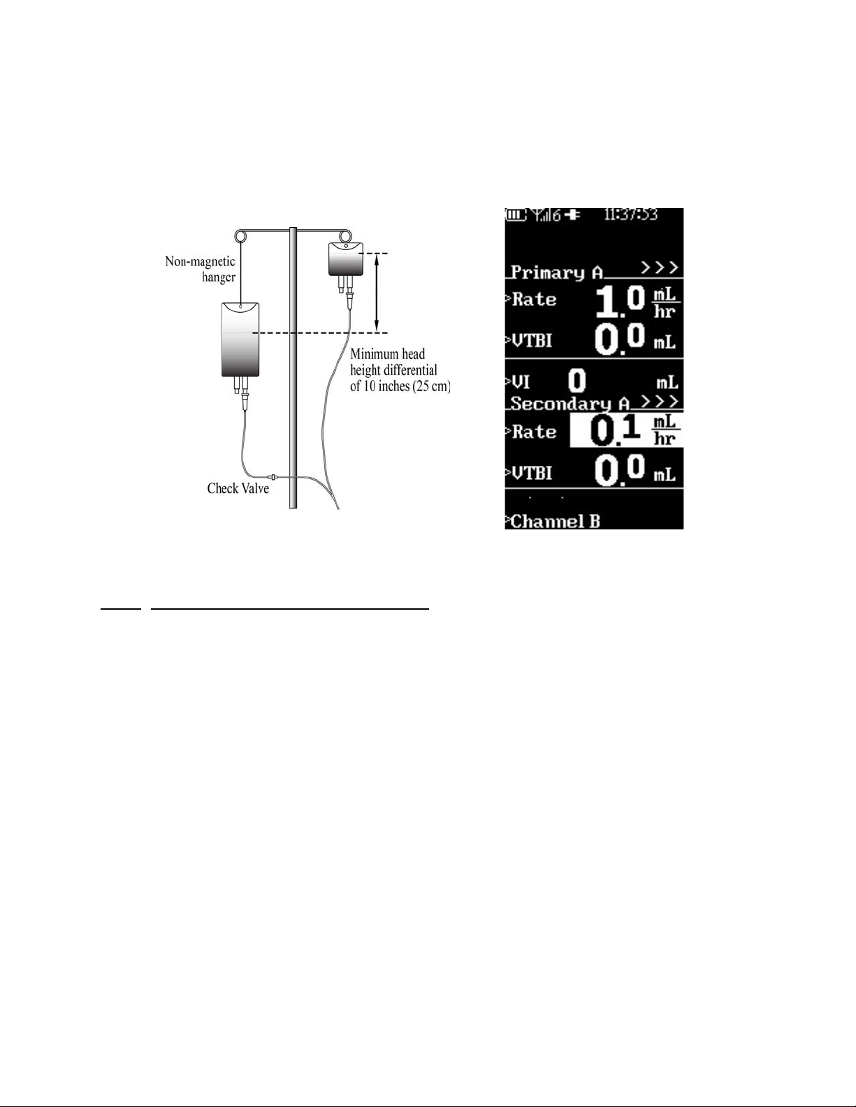
NOTE: Iradimed IV Sets 1055,1056, 1057 and 1058 do not have check valves. A
third part sterile check valve must be added when configuring a secondary
infusion.
Figure 4-3. Secondary Infusion Set-up and Programming Screen
4.2.3
secondary infusion in the primary configuration mode:
Programming a Secondary Infusion. Perform the following to program a
a. Press the SECONDARY soft key.
b. Observe that the programming screen splits to display Secondary Rate
and VTBI with the Rate value highlighted (See Figure 4-3).
c. Enter the desired flow rate using the numeric keys (or the up and down
arrow keys).
d. Press Enter or VTBI soft key.
e. Observe that the VTBI value is highlighted.
f . Enter the desired volume to be infused using the numeric keys (or the
up and down arrow keys).
g. Observe that the Ready to Start prompt is displayed.
h. Press the START/STOP Channel control key.
i. Observe that the secondary Rate and VTBI is displayed on the main
display screen.
• The green infusion running indicator light flashes.
• Confirm flow from the secondary fluid container by observing the
drip chamber.
4-7

• When the VTBI = 0 mL, the pump gives an audible alarm and the
primary parameters resume and are displayed.
WARNING: The clamp on the secondary set must be opened. If the clamp is
not opened, the fluid will be delivered from the primary container.
The Secondary VTBI must be equal to the volume in the secondary container.
Variables such as factory overfill and the amount of medication must be
considered when programming the VTBI.
Underestimating the secondary VTBI will result in the remainder of the secondary
solution to be delivered at the primary rate.
4.2.4
the primary settings while a secondary infusion is in process. Perform the following
to view the primary settings during a secondary infusion:
4.2.5
change the primary settings while a secondary infusion is in process. Perform the
following to change the primary settings during a secondary infusion:
4.2.6
the following to stop a secondary infusion and return to the primary infusion:
4.2.7
for viewing and changing the primary settings when a secondary infusion is running
move to the “Menu”. To view or change the primary settings:
Viewing Primary Settings during a Secondary Infusion. It is possible to view
a. Press the Adjust Primary soft key.
b. Observe that the primary parameters are now displayed on the central
display screen with the secondary infusion continuing without
interruption.
c. Press the CANCEL soft key to return to the secondary run screen (or
wait fifteen (15) seconds for Timeout Return).
Changing Primary Settings during a Secondary Infusion. It is possible to
a. Press the Adjust Primary soft key.
b. Observe that the Primary parameters are displayed with the Rate v alue
highlighted.
c. Press the RATE or VTBI soft key and set the new parameter(s) using
the numeric keys (or the up and down arrow keys).
d. Press Enter to accept the new values and return to Secondary display,
or press the CANCEL soft key to return to the secondary run screen.
Stopping a Secondary Infusion and Returning to Primary Infusion. Perform
a. Press the START/STOP Channel control key.
b. Observe that Cancel (A) or (B) is displayed as a soft key option.
c. Press Cancel (A) or (B) soft key.
• The pump is on hold and the light is not on.
d. The Primary infusion programming screen will display.
• To stop flow from the secondary container, the clamp on the
secondary set must be closed or the set disconnected from the
upper injection port.
e. Press START/STOP to restart at primary settings.
Dual Channel Operation. When both channel A and B are running, the options
a. Select MENU Key.
b. Press Primary A or Primary B Soft Key
c. Verify that Primary A Rate is highlighted. Use UP or DOWN arrow keys
to change if necessary.
d. Press VTBI Soft Key. Use UP or DOWN arrow keys to change if
necessary. Press ENTER to save changes and return o run screen.
4-8
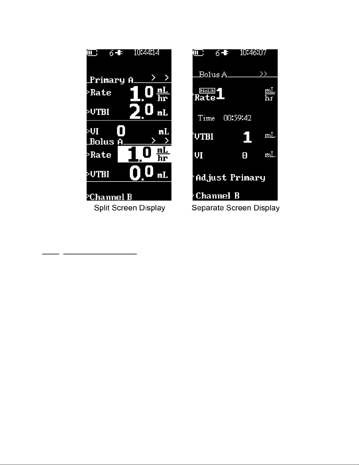
e. Press CANCEL to return to split running screen without making
changes.
Figure 4-4. Bolus Setup Displays
4.3 Bolus Delivery. The Bolus feature is used to deliver a bolus. The operator
enters this feature by selecting the Bolus option in the menu on the setup screen or
the running screen.
4.3.1
an infusion or added to an infusion in progress. Perform the following to program a
Bolus Dose for infusion:
NOTE: The VTBI of the Bolus cannot exceed the VTBI of the Primary infusion.
Bolus Setup and Start. The Bolus option may be programmed at the start of
a. Bolus A Soft Key: If the Channel B SideCar Option is installed and
Channel A channel is running pressing this soft key will allow Bolus A
selection.
b. Bolus B Soft Key: If the Channel B SideCar Option is installed and
Channel B channel is running pressing this soft key will allow Bolus B
selection.
c. Press BOLUS soft key from either the Primary programming, running
screen or menu.
• If from the primary programming screen the screen will split for
Bolus information (See Figure 4-4).
• If from the primary running screen, a separate Bolus display will
appear (See Figure 4-4).
• When both channels are running, the Bolus option is accessed from
the “Menu.” The screen will display “Bolus” for the channel chosen.
d. Observe that the Rate is highlighted.
e. Use the numeric keys (or up and down arrow keys) to enter the Bolus
delivery (the rate defaults to 500 mL/Hr, or other units as selected in
the Dose Rate Calculator).
4-9

f. Press the VTBI soft key.
g. Use numeric keys (or the up and down arrow keys) to enter Bolus VTBI
value.
h. Press Enter to accept (this starts the Bolus if programmed while the
pump is running).
i. If pump was not running, press the STAR T/ST OP Channel control key to
begin Bolus infusion.
j. Upon completion of the Bolus infusion, an audible alert sounds and the
primary infusion rate resumes with the VTBI counting down.
4.3.2
infusion:
4.3.3
Perform the following to restore a Bolus Dose:
Stopping Bolus Rate Dose. Perform the following to stop a Bolus Dose
a. Press START/STOP Channel control key
b. Press Cancel (A) or (B) soft key.
c. Observe that the Push Start (A) or (B) prompt is displayed.
d. Press the START/STOP Channel control key to resume the Primary
infusion parameters.
Restoring Bolus Dose. A Bolus Dose can be restored after it is complete.
a. Press BOLUS soft key from running screen or Menu.
b. Verify dosing parameters and press Enter control key. The Bolus begins
immediately.
NOTE: Confirm the primary mode parameters are correct before accessing the
Bolus Dose option. Bolus VTBI must be less than the primary VTBI.
4-10

Figure 4-5. Attaching Channel B “SideCar”
4.4 Channel B.
the MRidium
TM
pump. Perform substep 4.4.1 to add the Channel B SideCar and
(3861 I.V. Pump SideCar
TM
) A second channel may be added to
substep 4.4.2 to remove the Channel B SideCar.
IMPORTANT: 3861 Sidecar
model 3851 Sidecar
4.4.1
Attaching the Channel B SideCar. Perform the following to attach the Channel
TM
can only be used with 3860 or 3860+ Pumps. Earlier
TM
pumps will not operate with these units.
B SideCar:
a. Turn 3860 Pump OFF.
b. Remove SideCar port protector cap on rear of 3860 Pump. (Do not
discard protector cap).
c. Position the Channel B SideCar (See Figure 4-5) next to the left side
d. Slide the Channel B SideCar connection port onto the pump, press
e. Turn ON pump and verify start-up checkout (refer to section ).
4.4.2
B SideCar:
Detaching the Channel B SideCar. Perform the following to detach the Channel
a. Turn 3860 Pump OFF.
TM
of MRidium
3860 Pump
together and tighten two (2) thumb screws on the rear. Tighten upper
and lower screws a little at a time until secure. Do not overtighten the
thumbscrews.
4-11

b. Slide the Channel B SideCar backward to disconnect from main pump
after loosening upper and lower thumb screws.
c. Re-attach SideCar port protector cap on rear of 3860 pump.
IMPORTANT: After connecting the 3861 Channel B Sidecar
TM
do not turn off the
pump until the pump displays “New Patient” screen. During the startup process with the new Sidecar, the pump will verify and match the
sidecar software to that of the pump. Interrupting this process will
disable the sidecar and require return to Iradimed for repair.
4.5 Special Features Menu. There are additional features that are accessed by
pressing the MENU control key. Pressing the MENU control key brings up the Special
Feature Setup Menu to provide the operator with the ability to set the Dose Rate
Calculation, adjust the Alarm Volume, set the KVO Rate and adjust the Occlusion
Limit. Depending on optional accessories (i.e. Remote or Channel B) user may also
lock keyboard, set communication channel for Remote Display, program Bolus or
change/view primary infusion from this screen. Refer to Figure 4-6 for the various
screen options available with the Special Features Menu.
Figure 4-6. Special Features Menu
4-12

Figure 4-6. Special Features Menu (continued)
4-13

Figure 4-7. Dose Rate Calculation Menu
4.5.1
calculates a Rate based on a Dose amount, Patient Weight, and Concentration of
medication. There are three (3) modes of operation: the Basic Dose Rate Calculator,
the Dose Rate Calculator with Drug Library, and the Dose Rate Calculator with UserDefined Drug Library.(Refer to chart below and Default Values Table 1 in Appendix A.
The choices and ranges of dosing units are shown in Table 3B in Appendix A).
Dose Rate Calculation. The MRidiumTM 3860 infusion pump automatically
4-14

NOTE: Selecting a different drug name in the Drug Library changes the previous
concentration and dose rate values to the default values appropriate for the
selected drug. The choice of drug names cannot be modified by the user.
4.5.1.1 Basic Dose Rate Calculator - The Dose Rate Calculator feature is used
to calculate the volumetric rate for either Channel A or B, and is accessed
using the Menu key. The user is free to change the value of any field at any
time. When a new infusion rate is entered the dose value will change. When a
new dose value, weight, concentration or diluent value is entered the infusion
rate changes automatically. In this mode, the Drug Library is turned off in the
Service Mode.
NOTE: Secondary user preset values use the primary infusion preset values for
the medication selected. Separate secondary preset values can not be saved.
The example shown in Figure 4-7 is for Channel A. However, the dose calculation
screen used for channel B is the same except for the title and the soft key text that
is used to go to Channel A's dose calculation screen. Once the dose calculation
screen has been successfully completed, the dose rate a "Ready to Start" message
will appear in the lower, right-hand corner of the display. This message is used to
indicate that the user may press the "Start/Stop Channel" control key for the
appropriate channel.
Perform the following steps to select the Dose Rate Calculator:
a. Press the MENU control key.
b. Press the DOSE RATE CALC. (A or B) soft key. "Dose Rate Calc. B"
TM
message will only be visible if the Sidecar
(Channel B) has been
connected.
c. Observe that the Dose Rate Calculation Menu (See Figure 4-7) will be
displayed with the word "Primary" highlighted.
d. Use the up and down arrow keys to select Primary, Secondary or Bolus.
e. Press Enter.
f . Observe that the word “Drug?” is highlighted, which is the default drug
name.
NOTE: All factory default values in the Drug? Screen are shown in Appendix A,
and the user must enter appropriate values for all parameters before an infusion
can begin.
NOTE: In software revision 3.2.9 and higher, the Dose Rate Calculator Bolus
feature now defaults the Bolus Dose Units to “mL” so that the initial Bolus setting
choices are Volume and Time for any Bolus infusion, rather than the Rate &
Volume setting choices. With these new default settings, the Time default value is
set to 1 minute. All other Bolus Dose Units are still available (e.g. mcg/kg/hr,
mcg/kg, etc.), if appropriate, for the Dose Rate Calculator during programming.
g. Press ENTER or the DOSE soft key.
4-15

h. Observe that the Dose value is highlighted. Use the numeric keys (or
the up and down arrow keys) to set the desired Dose value. Press
ENTER, or the DOSE soft key. Observe that the units are highlighted.
Use the up and down arrow keys to choose the correct unit ordered.
NOTE: All available units choices for the dose and concentration settings are
provided in Table 3 in Appendix A.
i. Press ENTER or the CONC (concentration) soft key.
j. Observe that the concentration value is highlighted. Use the numeric
keys (or the up and down arrow keys) to enter the concentration of the
medication to be infused. Press ENTER, or the CONC soft key to
highlight the concentration units. Use the up and down arrow keys to
set the concentration units (see Table 3 in Appendix A for available
choices).
NOTE: Additional units choices for the dose and concentration settings are
available in software revision 3.0.XXXX and higher. Refer to Table 3 in Appendix A
for the list of these choices.
k. Press ENTER or the CONC soft key to highlight the base of the
concentration if it is greater than 1 mL. Use the numeric keys (or the up
and down arrow keys) to select this value.
l. Press ENTER or the WEIGHT soft key.
m. Observe that the Weight value is highlighted.
NOTE: If the patient weight is in pounds, divide that value by 2.2 to get weight in
kilograms.
n. Use the numeric keys (or the up and down arrow keys) to enter the
patient's weight in kg.
o. Press the appropriate VTBI, or Time (if displayed) soft key.
p. Observe that the selected value is highlighted.
q. Use the numeric keys (or the up and down arrow keys) to select the
value. Press ENTER to complete the selection.
r. The rate will automatically be calculated and the Ready to Start (A)
or (B) prompt will appear.
s. Verify
t. Press the START/STOP Channel control key. The Main running screen
will display with the correct parameters from the Dose Rate calculation
screen with the Rate value displayed between the Dose and VTBI
parameters (See Figure 4-8).
all entered values before starting infusion.
4-16

Figure 4-8. Primary Screen with Dose Rate Displayed
NOTE:
When the Pump is Stopped, “STBY” (Standby) will be displayed to the right
of Primary A in place of the pulsing “>>>”.
4.5.1.2 Dose Rate Calculator with Drug Library
feature is used to calculate the volumetric rate for either Channel A or B, and
is accessed using the Menu key. All factory default values in the Drug Library
are shown in Appendix A, and the user must enter appropriate values for all
parameters before an infusion can begin. The user is free to change the value
of any field at any time. When a new infusion rate is entered the dose value
will change. When a new dose value, weight, concentration or diluent value is
entered the infusion rate changes automatically. In this mode, the Drug
Library is turned on in the Service Mode, but no user-defined parameters hav e
been programmed.
Perform the following steps to select the Dose Rate Calculator with Drug
Library Calculator:
a. Press the MENU control key.
b. Press the DOSE RATE CALC. (A or B) soft key. "Dose Rate Calc. B"
message will only be visible if the Sidecar
connected.
c. Observe that the word "Drug?" is highlighted.
d. Use the up and down arrow keys to select the drug type (the choices
are: Drug? (which is the default drug name), Adenosine, Dobutamine,
Propofol, or Dexmedetomidine).
e. Press Enter.
- The Dose Rate Calculator
TM
(Channel B) has been
4-17

f . Observe that the Dose Rate Calculation Menu (See Figure 4-7) will be
displayed with the word "Primary" highlighted.
g. Use the up and down arrow keys to select Primary, Secondary or Bolus.
h. Press ENTER or the DOSE so ft key.
i. Observe that the Dose value is highlighted. Use the numeric keys (or
the up and down arrow keys) to set the desired Dose value. Press
ENTER, or the DOSE soft key. Observe that the units are highlighted.
Use the up and down arrow keys to choose the correct unit ordered.
NOTE: All available units choices for the dose and concentration settings are
provided in Table 3 in Appendix A for the list of these choices.
NOTE: In software revision 3.2.9 and higher, the Dose Rate Calculator Bolus
feature now defaults the Bolus Dose Units to “mL” so that the initial Bolus setting
choices are Volume and Time for any Bolus infusion, rather than the Rate &
Volume setting choices. With these new default settings, the Time default value is
set to 1 minute. All other Bolus Dose Units are still available (e.g. mcg/kg/hr,
mcg/kg, etc.), if appropriate, for the Dose Rate Calculator during programming.
j. Press ENTER or the CONC (concentration) soft key.
k. Observe that the concentration value is highlighted. Use the numeric
keys (or the up and down arrow keys) to enter the concentration of the
medication to be infused. Press ENTER, or the CONC soft key to
highlight the concentration units. Use the up and down arrow keys to
set the concentration units (see Table 3 in Appendix A for available
choices).
NOTE: Always program concentration first for fastest drug entries.
l. Press ENTER or the CONC soft key to highlight the base of the
concentration if it is greater than 1 mL. Use the numeric keys (or the up
and down arrow keys) to select this value.
m. Press ENTER or the WEIGHT soft key.
n. Observe that the Weight value is highlighted.
NOTE: If the patient weight is in pounds, divide that value by 2.2 to get weight in
kilograms.
o. Use the numeric keys (or the up and down arrow keys) to enter the
patient's weight in kg.
p. Press the appropriate Rate, VTBI, or Time (if displayed) soft key.
q. Observe that the selected value is highlighted.
r. Use the numeric keys (or the up and down arrow keys) to select the
value. Press ENTER to complete the selection.
s. The rate will automatically be calculated and the Ready to Start (A) or
(B) prompt will appear.
t. Verify all entered values before starting infusion.
u. Press the START/STOP Channel control key. The Main running screen
will display with the correct parameters from the Dose Rate calculation
screen with the Rate value displayed between the Dose and VTBI
parameters (See Figure 4-8)
4-18

4.5.1.3 User Defined Drug Library settings (Internal Drug Library)- The Dose
Rate Calculator feature is used to calculate the volumetric rate for either
Channel A or Channel B and is accessed using the Menu key. All starting userdefined values in the Drug Library are preset by service personnel, or the user
can enter alternate values for any parameter to begin an infusion. The user is
free to change the value of any field at any time. When a new infusion rate is
entered the dose value will change. When a new dose value, weight,
concentration or diluent value is entered the infusion rate changes
automatically . In this mode, the Drug Library is turned on in the Service Mode,
and the user-defined parameters have been programmed
.
NOTE: In this operating mode, the User-Defined Drug Library settings must be
set in the Service Mode. If no values have been set in the Service Mode, the
factory default values shown in Appendix A will be seen. The choice of drug names
cannot be modified by the user.
IMPORTANT: If the patient weight is entered and started on Channel A, if
Channel B is selected, the same weight will be entered on Channel B. However , the
patient weight can be changed without affecting the Channel A weight. These two
separate weights are retained on their respective channel until “NEW PATIENT” is
selected.
Perform the following steps to select the Dose Rate Calculator with UserDefined Drug Library Calculator:
a. Press the MENU control key.
b. Press the DOSE RATE CALC. (A or B) soft key. "Dose Rate Calc. B"
TM
message will only be visible if the Sidecar
(Channel B) has been
connected.
c. Observe that the medication name is highlighted. In this mode, the first
programmed medication in the service mode will appear first.
NOTE: If user-preset values for “Drug?” have been programmed in the service
mode, this label is changed to “Custom” to differentiate it from the default drug
name on the pump. “Drug?” may still be visible on the Remote/Charger unit.
d. Use the up and down arrow keys to select the drug type (the choices
are: Custom or Drug? (which is the default drug name), Adenosine,
Dobutamine, Propofol, or Dexmedetomidine).
e. Press Enter.
f . Observe that the Dose Rate Calculation Menu (See Figure 4-7) will be
displayed with the word "Primary" highlighted.
g. Use the up and down arrow keys to select Primary, Secondary or Bolus.
NOTE: Selecting a different drug name in the Drug Library changes the previous
concentration and dose rate values to the user-defined values for the selected
drug. If no User-Defined values are programmed, the parameters in the Drug
Library are preset with factory default values, and the user must enter appropriate
values for all parameters before an infusion can begin.
4-19

NOTE: In software revision 3.2.9 and higher, the Dose Rate Calculator Bolus
feature now defaults the Bolus Dose Units to “mL” so that the initial Bolus setting
choices are Volume and Time for any Bolus infusion, rather than the Rate &
Volume setting choices. With these new default settings, the Time default value is
set to 1 minute. All other Bolus Dose Units are still available (e.g. mcg/kg/hr,
mcg/kg, etc.), if appropriate, for the Dose Rate Calculator during programming.
h. Press ENTER or the DOSE so ft key.
i. Observe that the Dose value is highlighted. Use the numeric keys (or
the up and down arrow keys) to set the desired Dose value. Press
ENTER, or the DOSE soft key. Note that the units can not be modified
from the user preset values in this mode.
j. Press ENTER or the CONC (concentration) soft key.
k. Observe that the concentration value is highlighted. Use the numeric
keys (or the up and down arrow keys) to enter the concentration of the
medication to be infused. Press ENTER, or the CONC soft key to
highlight the concentration units. Note that the units can not be
modified from the user preset values in this mode.
l. Press ENTER or the CONC soft key to highlight the base of the
concentration if it is greater than 1 mL. Note that the units can not be
modified from the user preset values in this mode.
m. Press ENTER or the WEIGHT soft key.
n. Observe that the Weight value is highlighted.
NOTE: If the patient weight is in pounds, divide that value by 2.2 to get weight in
kilograms.
o. Use the numeric keys (or the up and down arrow keys) to enter the
patient's weight in kg.
p. Press the appropriate Rate, VTBI, or Time (if displayed) soft key.
q. Observe that the selected value is highlighted.
r. Use the numeric keys (or the up and down arrow keys) to select the
value. Press ENTER to complete the selection.
s. The rate will automatically be calculated and the Ready to Start (A) or
(B) prompt will appear.
t. Verify all entered values before starting infusion.
u. Press the START/STOP Channel control key. The Main running screen
will display with the correct parameters from the Dose Rate calculation
screen with the Rate value displayed between the Dose and VTBI
parameters (See Figure 4-8)
v. When infusing, the rate and dose are automatically transferred to the
main programming screen for viewing during this and subsequent
infusions.
4-20

IMPORTANT: The dose variables (dose and time) displayed on the running screen
can vary by very small amounts if the infusion is stopped and re-started without restarting from the Dose Rate Calculator. When infusing, the original parameter
programmed in the Dose Rate Calculator are used. Always verif y the Dose Rate
Calculator parameters for any subsequent or repeat infusion with the same patient.
IMPORTANT: If the patient weight is entered and started on Channel A, if
Channel B is selected, the same weight will be entered on Channel B. However , the
patient weight can be changed without affecting the Channel A weight. These two
separate weights are retained on their respective channel until “NEW PATIENT” is
selected.
4.5.1.4 Dose Rate Calculator with Dose Error Reduction System (DERS)
Refer to Section 8 for operation of the Dose Rate Calculator with user defined
drug library and the optional Dose Error Reduction System (DERS).
Figure 4-9. Alarm Volume Adjustment Screen
4.5.2
adjust the audio volume for user alerts and alarms (See Figure 4-9). The pump will
sound the alarm during adjustment to provide an indication of the current setting of
the volume. The volume range is on a visual sliding scale. Perform the following to
adjust the Alarm Volume:
NOTE: The Alarm Volume setting in the MENU option of the Pump and Remote
Display/Charger only
Volume setting on the R emote Display will not
the Pump.
Alarm Volume The MRidiumTM 3860 MRI Infusion Pump allows the clinician to
a. Press the MENU control key.
b. Press the ALARM VOLUME soft key.
c. Press the up and down arrow control keys to adjust the volume.
d. Press ENTER.
e. Press the CANCEL control key to return to the run or programming
display screen
controls the unit being adjusted. Adjusting the Alarm
change the Alarm Volume setting of
4-21

NOTE: Setting the alarm volume also sets the SpO
Pulse Tone volume when it is
2
installed and enabled (3860+ only).
4.5.3 KVO Rate. The MRidiumTM 3860 MRI Infusion Pump will default to a preset
KVO (Keep Vein Open) rate (See Figure 4-10) when the Primary infusion VTBI
counts down to 0 mL. When the VTBI is 0 mL, the infusion automatically switches to
the configured KVO rate, with KVO flashing in the VTBI value area, or remains at the
programmed primary flow rate, whichever is less. [Figure 4-10a shows a completed
infusion with the KVO Rate = 0 mL/Hr (infusion is completed and not infusing). A
reminder tone continues until the alert is acknowledged by the user. Figure 4-10b
shows a completed infusion with the KVO Rate = 1 mL/Hr. This infusion sounds a
single alert that the infusion has completed infusing at the KVO rate, which can be 1,
2, 3, 4 or 5 mL/Hr]. This KVO rate may be set to a value between 0-5 mL/hr,
according to your hospitals policy. From the Special Feature Setup Menu. Perform
the following to adjust the KVO Rate:
NOTE: When the KVO rate is set to 0 (off), and the infusion is complete, the short
tone will occur, and the infusion will stop. As with a paused infusion, the pump will
give a periodic audible tone every 15 seconds to remind the operator that the
pump is not infusing (unless the reminder beep has been set to “OFF” in the
service mode). When the infusion is paused, “STBY” symbol is displayed adjacent
to the paused channel. To continue, press the “CANCEL” key to access the set-up
screen.
a. Press the MENU control key.
b. Press the KVO Rate soft key.
c. Press the soft key corresponding to the Channel you wish to change (if
the optional second channel is not present then only Channel A will be
available).
NOTE: Always select the appropriate KVO rate for the prescribed fluid therapy.
d. Use the up and down arrow control keys to adjust limit between 0-5
mL/hr. (0 shuts off the KVO infusion).
e. Press ENTER.
f . Press the CANCEL control key to return to the main programming
screen.
NOTE: This option may appear on the second Menu page.
4-22

4-10a 4-10b
Figure 4-10. KVO Rate Screen
4.5.4
Occlusion alarm when there is an occlusion between the infusion fluid source and the
pump. Patient Occlusion alarm will display when there is an occlusion between the
pump and the patient; this alarm has an adjustable pressure limit between 1-10 PSI
(6.9 to 68.8 kPa). Occlusion is detected by building of pressure in the I.V. Line
downstream of the pump.
NOTE: If the alarm recurs without apparent cause, the Occlusion Pressure Limit
may be set too low. Readjust Occlusion Pressure Limit accordingly. Ensure that
occlusion pressures chosen are clinically appropriate.
Perform the following to adjust the Occlusion Pressure Limit:
NOTE: Dual Channel Operation:
both Channel A and Channel B.
Occlusion Limits. The MRidiumTM 3860 MRI Infusion Pump will display an Inlet
a. Press the MENU control key.
b. Press the OCCLUSION LIMIT soft key.
c. Use the up and down arrow control keys to adjust limit between 1-10
PSI (6.9 to 68.8 kPa).
d. Press ENTER.
e. Press the CANCEL control key to return to the main programming
screen.
The KVO Rate and the Occlusion Limit apply to
4-23

4.5.5 Lock Keys. This feature allows the user to prevent an accidental key
activation. The Lock Key option will not be displayed unless it has been enabled in
the Service Mode.
Perform the following to activate Key Lock:
a. Press the MENU control key.
b. Press the LOCK KEYS soft key.
c. Verify all keys are locked except Menu.
d. If any other key is pressed a tone will occur to denote that key is
locked.
Perform the following to deactivate Key Lock:
a. Press the MENU control key.
b. Press the UNLOCK KEYS soft key.
c. Verify all keys are now unlocked.
This feature is reserved for service personnel to enable, contact Service/Biomedical
department for activation (details of this activation are included in the MRidium
TM
3860 MRI Infusion Pump Service Manual, part number 1125). This option may
appear on the second Menu page.
4.5.6
NEXT MENU key The NEXT MENU will appear if the Remote Display option or
the Channel B SideCar option is installed, pressing the NEXT MENU soft key will
display additional menu options.
a. Set Comm Channel: If the remote control option is installed pressing
this soft key will select the Radio Channel selection menu.
WARNING: Upon signal reacquisition between the Pump and the Remote
Display, always visually confirm that both Pump and Remote displays change with
a selection of the MENU key (this won’t affect the Pump operation if it is infusing).
If using multiple Pumps with the same Remote Display/Charger, always program
each Pump with its unique radio-link channel (Channels 1 through 6) in the Setup
Menu. Additionally, when changing the Remote Display/Charger radiocommunication channel, always
selected Pump. This can be done in many ways, but the easiest way is to select the
MENU key on the Remote Display/Charger and visually confirm that the Pump’s
display matches this change. Pressing the CANCEL key on the Remote Display/
Charger should then return both displays to the original display . Doing this at least
once before any Pump programming will acknowledge that proper communication
has been established between the Remote Display/Charger and the selected
Pump.
4.5.7
Radio Channel menu. Press the Channel soft key to highlight the desired
channel. Both Remote and Pump must be set to the same channel.
re-confirm proper communication with the
4-24

Figure 4-11. Set Comm Channel Displays
4.5.8
the MENU or CANCEL control key. The pump will return to the Primary Pump Setup
screen where setup of the Primary Pump may be performed.
4.6 Air Bubble Detection and Reset. The pump has an air bubble detector that
will detect air bubbles (that are greater than 100 uL) which pass in front of it. When
this happens the infusion will stop and the pump will alarm. Once the condition has
been corrected the infusion cycle must be manually restarted.
4.7 Data Retention. The pump program settings and option selections are
retained in nonvolatile memory. If the pump has been turned off for longer than one
(1) hour, delivery settings are cleared. The History Log data, which stores a
comprehensive range of the pumps operational information, is retained indefinitely
on a FIFO (First In - First Out) basis. The History Log holds approximately 3,000 to
5000 entries and alarms. It can be downloaded from the Pump into a computer to
review. This is accessed in the Service mode. (Please see Service Manual 1125 for
more details).
Exiting the Special Features Menu. To exit the Special Features Menu, press
4-25

4-26

SECTION 5
ALARMS
5.0 Alarms.
5.1 Introduction.
5.2 User Messages. There are three (3) types of user messages (Alarms, Alerts
and User Prompts) displayed on the pump in the users message area (See Figure
5-1). The following is a description of the user messages:
a. Alarm. Major Pump or Channel related problem.
• The infusion stops.
• The RUN/ALARM Lamp illuminates RED and flashes
• The audible alarm tone sounds
• An alarm message can appear at top of Main Display
b. Alert. Indicates a change in the infusion status.
• The infusion continues to operate
• The RUN/ALARM Lamp illuminates GREEN and flashes
• The audible tone sounds
• An alert message can appear at top of Main Display
NOTE: During SpO2 related Alerts/Alarms, the infusion does not stop, and the
Run/Alarm lamp can flash both green and red together during these events.
c. User Prompt. Informational update, the infusion status has not
changed
• Generally, some steps were not completed or an incorrect key
• Prompt message can appear at top of Main Display.
NOTE: When using the Pump with both Channel A and Channel B operating, some
messages will indicate “Channel A” or “Channel B” to identify which channel is
affected. Always verify the appropriate channel is selected before making any
changes. If both channels are alarming, both RUN/ALARM indicators will be
flashing RED and the alarm message at the top of the Main Display will alternate
both messages.
See Table 5-1 for a listing of all the messages (Alarms, Alerts and User Prompts)
that the pump might display. The table is divided into four columns with the first
column providing the message which appears on the screen, the second identifies
the type of message (Alarm, Alert or User Prompt), the third identifies the cause of
the message and the fourth contains the suggested action in response to the
message.
5.3 Responding to an Alarm. Perform the following to respond to an alarm:
a. Press the Alarm Silence control key to silence the sound and re-
set the Alarm Condition monitor.
b. Resolve the alarm condition (i.e.: clear bubble, change battery, close
door, etc.)
c. Press the Start/Stop control key for the appropriate channel to continue
the infusion.
.
was pressed.
5-1

5.4 Remote Alarms. All alarms must be resolved at the pump. Alarms are listed
in Table 5-1.
WARNING: Always Respond to patient at the pump if an alarm occurs. Do not
rely on the remote alarm silence function. Patient injury could occur.
Figure 5-1. Alarm Display in User Message Area
5-2

Table 5-1. Alarm, Alert and User Prompt Messages
MESSAGE TYPE CAUSE RESOLUTION
BAD BATTERY Alert Battery fault has occurred Remove from use. Contact qualified
service personnel
BATTERY
DEPLETED
Battery Low Alert Battery has 30 minutes or less
Bubble Detected
(A) or (B)
Changes not
allowed (DERS
Only)
Check Door
(A) or (B)
Close Door
(A) or (B)
Alert Battery is too low to operate
Pump much longer.
of charge remaining.
Alarm Air detector has detected an
air bubble larger than the 100
uL threshold.
Prompt Titration from the running
screen is the only method of
dose adjustment, unless the
infusion is stopped.
Alarm Possible free flow of I.V. fluid Be sure door clamp is closed tightly
Alarm Latch was opened during an
infusion.
Plug AC Adapter power cord into an
AC outlet immediately. Make sure
Adapter is plugged into the Pump.
Plug Pump into AC Adapter, and/or
AC Adapter power cord into an AC
outlet as soon as possible.
Evaluate air in set. Open Pump Door
latch to remove set. Remove air per
hospital protocol. Reinstall set.
Press START/STOP to resume
infusion.
Press CANCEL to switch to the main
Running screen to modify the active
parameters (e.g. Dose, VTBI, or
Time, dependent on the infusion
settings). Otherwise, press START/
STOP to stop the infusion, then
press CANCEL, then access the Dose
Rate Calculator Menu to modify any
of the infusion parameters.
flush with door. Open and reclose
door or assure Free Flow Preventer
is pulled out to stop position.
Check for proper set installation.
Close latch. Press START/STOP to
resume infusion.
Close Door
(A) or (B)
Completed Prompt Infusion has been completed,
Critical Error xxx
or Service Code
xxx
DEAD BATTERY Alarm Battery too low to operate
Dose Complete
(Audible Only)
Prompt Latch is open (prior to starting
an infusion). Message occurs
with an audible beep that
repeats every 10 seconds.
and KVO Rate is set to zero
(0). Current VTBI = 0. No fluid
is infusing at this time.
Alarm Pump Run Test fails, other
motor tests, hardware or
software conflict.
Pump.
Alert A dose delivery has just been
completed. Message with an
audible beep.
Close latch fully downward.
Press CANCEL to reset infusion to
initial parameters. Periodic reminder
tone will be heard (unless the
reminder beep has been set to
“OFF” in the service mode) until
user acknowledges the infusion is
complete.
Remove from use. Contact qualified
service personnel.
Plug Pump into AC Mains Power.
Press ON key and choose “Same
Patient” to resume infusion.
No action necessary. Pump enters
KVO.
5-3

MESSAGE TYPE CAUSE RESOLUTION
History Checksum
Error
Inlet Occluded
(A) or (B)
Load Set
(A) or (B)
MAX Rate
(Audible Only)
No
Communication
(Remote Display
unit only)
Prompt Pump detected a memory or
power failure. Existing
operating parameters have
been erased.
Alarm Flow has been obstructed
between fluid container and
Pump.
Prompt Pump needs to verify operation
(establish pressure baseline
and perform motor test).
Prompt Calculated rate is outside
allowable range. An audible
beep occurs if key is pressed
to attempt to move dose out of
range.
Alert Communication between pump
and Remote Display has been
interrupted.
Pump has reverted to the default
program settings. Press MENU to
examine settings, and reenter any
needed infusion setting changes.If
message recurs, refer to service
personnel for CR2032 coin cell
replacement.
Check administration set for
probable cause (kinked tubing,
clogged filter, etc.). Press Start/Stop
(for appropriate channel) to restart
infusion.
Open Pump Door until message
disappears. Close Door to resume
infusion. Always turn Pump on prior
to loading set.
Verify and reenter settings.
Repo sition Remote Display or Pump
to re-establish communication. Be
sure Pump is still ON.
Interference from another Radio
source may cause problem. Go to
an alternate Comm channel on both
Pump and Remote Display.
Otherwise, refer unit to qualified
service personnel.
OVR Pro mpt Over-Ran ge of Rate or VTBI
established settings.
Press ENTER Prompt Value change confirmation
Pressure Error
(A) or (B)
Pt Occluded
(A) or (B)
(Patient
Occluded)
Rate too high Prompt Calculated rate exceeds the
Prompt Excessive variation in pressure
Alarm Pressure in I.V. line has
required.
due to motion, flow from other
Pumps or blood pressure
prevents accurate setting of
pressure baseline.
exceeded Adjustable Pressure
Limit due to elevated
resistance in delivery path
between pump and patient.
maximum rate of the pump
(i.e. 1400 mL/hr).
Reset values to be within
parameters: Rate: 1.0 to 1400 mL/
hr VTBI: 0.1 to 9,999 mL
Verify selection and press ENTER.
Open and Close door to reset
pressure sensors. Press START/
STOP key to start infusion.
Check administration set for
probable cause (kinked tubing,
closed stopcock, high resistance
catheter, etc.). Press START/STOP
key to restart infusion.
Infusion cannot be started with the
existing values. Modify the selected
parameter to allow the infusion to
proceed. Review and verify the new
infusion parameter(s) before
starting the infusion.
5-4

MESSAGE TYPE CAUSE RESOLUTION
Rate too low Prompt Calculated rate is below the
minimum rate of the pump
(i.e. 0.1 mL/hr).
Recheck Settings,
Press Enter to
restart
Re-enter settings,
press ENTER to
continue
Review Bolus Prompt A selected parameter that
Review Primary Prompt A selected parameter that
Prompt Calculated Dose Rate
Calculator values are outside
allowable range.
Prompt Selected values are outside
allowable range.
affects a Bolus infusion
calculated value (e.g. Dose,
CONC, Weight, etc.) has been
modified after setting up an
infusion.
affects a Primary infusion
calculated value (e.g. Dose,
CONC, Weight, etc.) has been
modified after setting up an
infusion.
Infusion cannot be started with the
existing values. Modify the selected
parameter to allow the infusion to
proceed. Review and verify the new
infusion parameter(s) before
starting the infusion.
Press the ENTER key. Previous
values are replaced with default
values. Verify and reenter new
settings.
Press the ENTER key. Previous
values are replaced with default
values. Verify and reenter new
settings.
Select the Dose Rate Calculator
Bolus Infusion screen. Infusion can't
be started without reviewing this
setup screen. Review and verify the
new infusion parameter(s) before
starting the infusion.
Select the Dose Rate Calculator
Primary Infusion screen. Infusion
can't be started without reviewing
this setup screen. Review and veri fy
the new infusion parameter(s)
before starting the infusion.
Review Secondary
(when using
DERS or software
version 3.0.xxx or
higher , Secondary
infusion is not
available)
Settings Lost Prompt Message occurs at power up to
Unload Set Prompt Pump needs to reset air in line
UND Prompt Under-Range of Rate or VTBI
Prompt A selected parameter that
affects a Secondary infusion
calculated value (e.g. Dose,
CONC, Weight, etc.) has been
modified after setting up an
infusion.
indicate the existing operating
parameters have been erased
due to internal battery failure,
and the system has reverted
back to initial default
parameter settings.
detector.
established settings.
Select the Dose Rate Calculator
Secondary Infusion screen. Infusion
can't be started without reviewing
this setup screen. Review and veri fy
the new infusion parameter(s)
before starting the infusion.
Re-enter patient’s infusion settings.
If message recurs, refer the pump
to qualified service personnel for
repair.
Open door. Remove and replace I.V.
set. Close door. Always turn Pump
ON prior to loading set.
Reset values to be within
parameters: Rate: 1.0 to 1400 mL/
hr VTBI: 0.1 to 9,999 mL
5-5

MESSAGE TYPE CAUSE RESOLUTION
VTBI = KVO
(Audible Only)
VTBI too high Prompt Calculated VTBI exceeds the
VTBI too low Prompt Calculated VTBI is below the
X ABOVE HARD
Hospital defined
drug specific
Limits can be set
for Dose, Dose
Infusion Time,
Patient Weight,
Bolus Dose and
Bolus Infusion
Time.
Alert VTBI has counted down to
zero. Channel is in KVO mode.
maximum VTBI of the pump
(i.e. 999 mL).
minimum VTBI of the pump
(i.e. 0.1 mL).
Prompt Selected Channel X (A or B)
value exceeds the hospital
defined DERS maximum limit.
The maximum limit value
and ‘Above Hard Limit’
message is alternately
displayed at the top of the
screen when this prompt
occurs.
Press the appropriate channel's
START/STOP to stop infusion, then
press ENTER and the VTBI Soft Key
to reenter the new VTBI. Change
solution container, if necessary. If
therapy is complete, remove tubing
from pump to end infusion.
Infusion can't be started with the
existing values. Modify the selected
parameter to allow the infusion to
proceed. Review and verify the new
infusion parameter(s) before
starting the infusion.
Infusion can't be started with the
existing values. Modify the selected
parameter to allow the infusion to
proceed. Review and verify the new
infusion parameter(s) before
starting the infusion.
During Primary Infusion
Programming: The primary
infusion cannot be started with the
existing values. Modify the selected
parameter to within the acceptable
limits and proceed with
programming.
During Titration of a Primary
Infusion: If this prompt occurs
during the titration of the primary
infusion you must modify the
selected parameter to within
acceptable limits.
If no entry is made the change will
cancel automatically within 10
seconds and the prompt will no
longer appear on the display screen.
5-6

X ABOVE soft
limit
Ye s-Enter /
Cancel-No
Hospital defined
drug specific
Limits can be set
for Dose, Dose
Infusion Time,
Patient Weight,
Bolus Dose and
Bolus Infusion
Time
Prompt Selected Channel (A or B)
value exceeds hospital defined
DERS high limit.
The high limit value and
‘ABOVE SOFT limit’ message is
alternately displayed at the top
of the screen when this prompt
occurs.
Yes-Enter / Cancel-No is a
stationary screen prompt and
does not alternate with the
aforementioned.
During Primary Infusion
Programming: The user must
press ENTER to accept the
parameter above the High Limit or
press CANCEL and enter a value
within acceptable limits and proceed
with programming.
During Titration of a Primary
Infusion: If this prompt occurs
during the titration of the primary
infusion you must press ‘ENTER’ to
accept the parameter above the
High Limit or press CANCEL and
enter a value within acceptable
limits.
If no entry is made the change will
cancel automatically within 10
seconds and the prompt will no
longer appear on the display screen.
X BELOW HARD
limit (DERS only).
Hospital defined
drug specific
Limits can be set
for Dose, Dose
Infusion Time,
Patient Weight,
Bolus Dose and
Bolus Infusion
Time.
Prompt Selected Channel (A or B)
value exceeds the hospital
defined DERS minimum limit.
The minimum limit value and
‘Below Hard Limit’ message is
alternately displayed at the top
of the screen when this prompt
occurs.
During Primary Infusion
Programming: The primary
infusion cannot be started with the
existing values. Modify the selected
parameter to within the acceptable
limits and proceed with
programming.
During Titration of a Primary
Infusion: If this prompt occurs
during the titration of the primary
infusion you must modify the
selected parameter to within
acceptable limits.
If no entry is made the change will
cancel automatically within 10
seconds and the prompt will no
longer appear on the display screen.
5-7

X BELOW soft
limit
Ye s - En ter /
Cancel - No
(DERS only).
Hospital defined
drug specific
Limits can be set
for Dose, Dose
Infusion Time,
Patient Weight,
Bolus Dose and
Bolus Infusion
Time.
Prompt Selected Channel (A or B)
value exceeds hospital defined
DERS lower soft limit.
The lower soft value and
‘Below SOFT limit’ message is
alternately displayed at the top
of the screen when this prompt
occurs.
Yes-Enter / Cancel-No is a
stationary screen prompt and
does not alternate with the
aforementioned
During Primary Infusion
Programming: The user must
press ENTER to accept the
parameter below the lower soft
Limit or press CANCEL and enter a
value within acceptable limits and
proceed with programming.
During Titration of a Primary
Infusion: If this prompt occurs
during the titration of the primary
infusion you must press ‘ENTER’ to
accept the parameter below the
lower soft Limit or press CANCEL
and enter a value within acceptable
limits.
If no entry is made the change will
cancel automatically within 10
seconds and the prompt will no
longer appear on the display screen
Refer to Section 7.8 for SpO2 related Alarms, Alerts, and user prompt messages.
5-8

SECTION 6
BATTERY OPERATION
6.0 Battery Operation.
6.1 Introduction. The 3860 system includes a smart Battery Pack that self-
monitors its performance and status and communicates this information to the
Pump. This allows the Pump to monitor the battery parameters in order to maximize
the life of the battery, reduce battery-related costs and minimize Pump/Battery
down-time.
NOTE: The Battery Pack is sealed such that the batteries can’t be replaced. If the
Battery Pack fails or becomes unusable, do not attempt to replace the internal
batteries. Replace the Battery Pack. Contact Iradimed Corporation for disposal.
6.2 Inserting the Battery Pack. P erform the following to insert the Battery Pack
into the pump or Remote Display/Charger:
a. Grasp the Battery Pack firmly.
b. Slide the Pack into the battery compartment on the rear of the Unit.
Push in firmly until the pack snaps into place. The Battery Pack can be
inserted when the Unit is either turned On or Off.
c. After the Unit is turned On, verify that the Battery Icon on the Main
Display has the “X” removed and the Icon is filled or filling during the
charge cycle.
Figure 6-1. Battery Installation
6.3 Charging the Battery Pack. After insertion of the Battery Pack, attach the
Power Adapter to the Pump and the AC power source. The battery will charge
automatically whenev er the pump is connected to the AC power source as indicated
by a visible Amber LED indicator on the Pump front panel. The Battery Pack can be
inserted when the Pump is either turned On or Off.
After the Pump is turned On, verify that the Battery Icon on the Main Display has the
“X” removed and the Icon is filled or filling during the charge cycle.
6-1
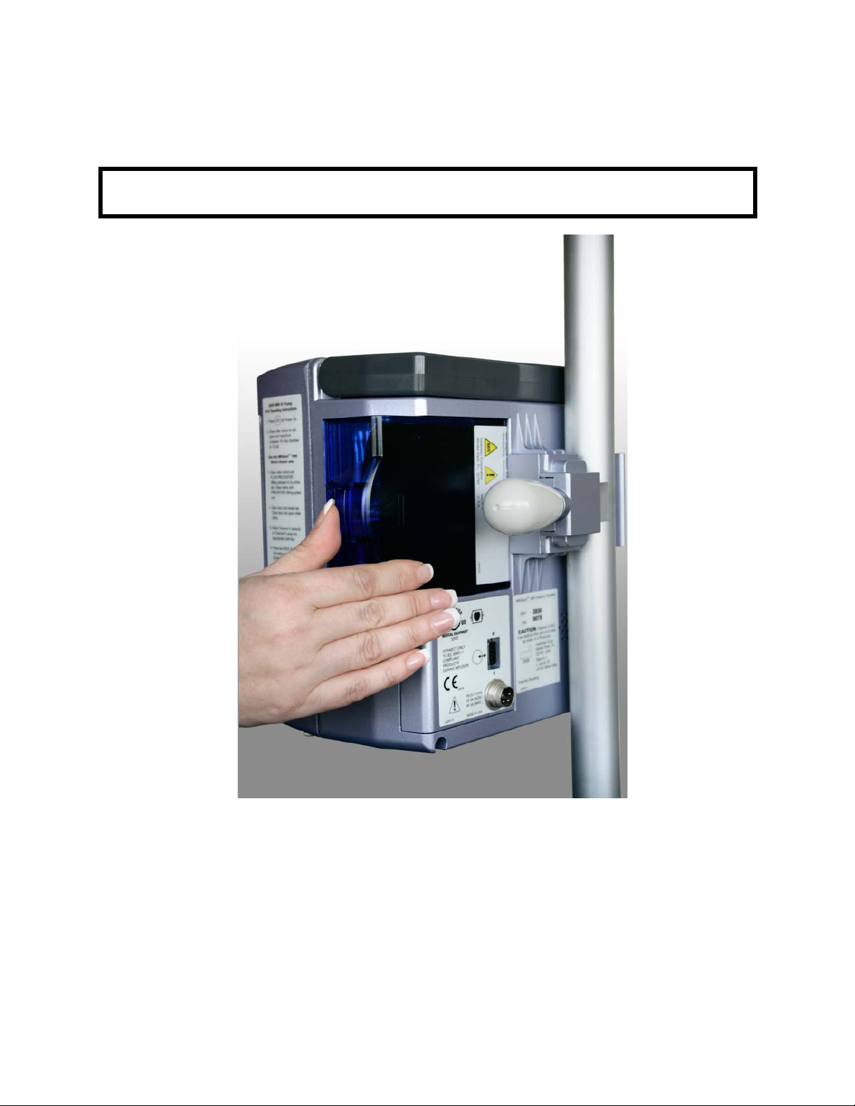
6.4 Removing the Battery Pack. Press in the Battery Pack latch located on the
right side of the installed Pack. Grasp the Pack, and pull it outw ard from the Pump’s
Battery compartment. Another new or charged battery Pack can now be placed into
the Pump. The Battery Pack can be removed when the Pump is either turned On or
Off.
WARNING: The Battery Pack is slightly magnetic. Do not remove Battery Pack
inside the MRI Scan Room.
Figure 6-2. Battery Removal
6.5 Testing the Battery Pack. The battery capacity , relative to a new battery, is
evident on the Battery Icon. When the Pump is “On”, the actual charge status of the
Battery Pack can also be tested without the use of the Pump. Depress the small
button on the rear of the Battery Pack, as indicated on the Battery Pack Label. When
pressed the Battery Level LED indicators will momentarily show the charge status,
which is expected to diminish as the battery pack ages. (The indicators can range
from five (5) L.E.D.s illuminated for fully charged, to one flashing L.E.D. illuminated
for fully discharged).
6-2

Figure 6-3. Battery Test
6.6 Battery Charge Indicator. The Battery Gauge on the Main Display indicates
approximate battery capacity remaining under current operating conditions. It is
located in the upper portion of the display and is always visible. Check the remaining
battery capacity when starting an infusion. The Battery Gauge updates continuously
while infusing.
a. The battery recharges whenever the Pump and its Power Adapter is
plugged into an AC power outlet, or optionally when the Battery Pack is
inserted into the Remote Display Unit.
b. The system includes:
• A green/amber light that illuminates when Pump/Remote is
plugged in to the AC power with the Power Adapter.
• An amber light that illuminates when Pump is charging the
battery, green indicates charging current termination, and the
Battery Pack is fully charged.
• Automatic switchover to battery power if Pump is unplugged or in
the event of a power failure.
Note: This automatic switchover is not applicable in the Remote Display Unit,
as it cannot operate on battery power.
6.7 Battery Low Indication. A Low Battery alert indicating that battery
depletion is imminent, beginning at least 30 minutes prior to a depleted battery
alarm. For best results, fully charge, discharge and recharge the battery before
putting the Pump into service. Battery run time will be affected by the operating
mode, rate, and back pressure.
Should the battery “smart power gauge” detect an over-discharge of one or more
internal cells, the pump will provide a “BAD BATTERY” alarm condition. The pump
should be turned off and on and recharged immediately to prevent battery damage.
Restart/power cycle the pump and select Previous Patient to continue infusion.
CAUTION: If Pump is in storage and not used for more than 30 days, the
battery pack should be removed.
6-3

6.8 Battery Power Gauge. Located at the top left of the informational display,
this gauge is in the shape of a battery and provides a visual indication of the
capacity status of the battery. When the gauge is “full,” then the battery is at full
design capacity, relative to when the battery was new; when the gauge is “empty,”
then the battery is nearly depleted and the pump may not operate unless connected
through the MRI Power Supply (pump only) to a hospital grade AC outlet. When the
battery is removed, the gauge has an “X” placed inside it. If the Battery Operating
time seems short, the battery gauge may require re-calibration, to accomplish this,
perform the following:
a. Remove pump from clinical use. Set up pump to operate on battery
power.
b. Operate pump until low power alarm occurs, continue to operate until
the “DEAD BATTERY” alarm (capacity <2%) occurs.
c. Reconnect the pump to the 1120 MRI Power Supply or move the fully
depleted battery to the Remote Display/Charger, and allow the pump
battery to fully recharge. When in the pump recharging can occur
during normal use if the pump is connected to its 1120 MRI Power
Supply. The battery should recharge in less than nine (9) hours.
d. If battery life is still short, refer to qualified service personnel.
6.9 Battery Care and Maintenance:
6.9.1 Introduction. Over discharge, over charge and over current (short-circuit)
are all conditions detected by the internal “smart power gauge” of the battery . These
conditions all result in the battery shutdown (battery will not deliver power) until
placed into charge. Over discharge can cause cells to outgas during subsequent
charge cycles. Severe outgassing can result in the battery pack swelling. Replace
any battery pack with visible signs of deformation or swelling.
6.9.2 1133 Battery Pack Maintenance Checkout Procedure.
The 1133 Battery Pack should be inspected anytime the pack is removed, or at least
every 90 days for the following:
a. Battery Pack communicates with the Pump.
Battery Icon being shown on the display of the Pump or Remote
Display. Refer to Section 1.3.1 of this manual for Battery Icon
description.
b. The Battery Pack holds sufficient operating charge capacity .
indicated by allowing the Pump to operate on battery power for the
recommended minimum time.
c. Battery Pack "Gas Gauge" indicator functions.
confirmed by performing the checks defined in Sections 6.5 and 6.6
above.
d. Physical Inspection of the Battery Pack case.
from the Pump or Remote Display, and inspect for physical damage or
signs of mechanical shock, cracked casing or swollen case.
e. Physical Inspection of the Battery Pack cell(s).
Pack from the Pump or Remote Display, and confirm that cells inside
the Battery Pack are not swelling excessively, as noted by viewing
internal cells from the edge of the Battery Pack case. Swollen cells that
are greater than 8 mm thick, or cause the Battery Pack's plastic case to
bulge indicate a failing battery pack.
Any failure of any of the above inspection criteria will require discontinuance of use
and replacement of the 1133 Battery Pack.
6.10 Battery Pack Replacement. If the Battery Pack does not operate for the
specified time after a full nine (9) hour charge cycle, replacement of the Battery Pack
is recommended.
This indicated by the
This is
These functions can be
Remove the Battery Pack
Remove the Battery
6-4

CAUTION: If placed into storage, to mainta in battery life, assure that the
battery pack remains charged above 25% (one battery segment is visible)
as indicated by the “gas gauge” LED display.
6.11 Battery Pack Related Precautions.
The 1133 Battery Pack contains several lithium-polymer cells and an integral safety
circuit. As these cells age, they can expand due to internal gas release, which is
anticipated for this type of cell. However, if excessive expansion occurs, this can
result in the battery case expanding (swelling), and possibly cause failure of the
battery case, cells, or safety circuit. If this is observed, remove the Battery Pack
from use and replace it as soon as possible.
The 1133 Battery Pack contains protective circuitry to prevent catastrophic battery
failure. If the Battery pack is damaged, this protective circuitry may not prevent
battery failure. Remove the Battery P ack fr om use if the Pack becomes damaged, or
the potential for Battery Pack damage is suspected.
Do not use a damaged or swollen 1133 Battery Pack.
Avoid damage to the 1133 Battery Pack by impact, dropping, overheating, or
mechanical abuse. Never compress, drop, shock, or strike the 1133 Battery Pa ck.
Never use objects that could puncture the internal battery cells. Any of these
actions can cause the battery cells to heat, smoke, or cause catastrophic battery
failure, which could result in fire.
Do not attempt to disassemble the 1133 Battery Pack. Damage caused by
disassembly or tool use can result in catastrophic battery failure, which could result
in fire.
If the 1133 Battery Pack case begins to expand and/or swell, discontinue battery
charging and use immediately, and replace the Battery Pack. Continued charging
will cause further Battery Pack case expansion, with possible battery case fracture,
and potential electrolyte leakage.
If the 1133 Battery Pack becomes damaged, avoid contact with the battery cell
electrolyte. If the electrolyte contacts the skin or eyes, seek medical attention
immediately.
If the 1133 Battery Pack shows sign of the battery case expanding (swelling),
remove the Battery Pack from use and replace it as soon as possible. In extreme
conditions, this swelling can cause the 1133 Battery Pack to become jammed or
stuck within the 3860 Pump or 3865 Remote Display, and/or cause the Battery Pack
plastic case to burst open. If this occurs, do not use tools that could cause damage
to the internal battery cells. Refer to the 1125 Service Manual for removal under
these conditions.
Under no circumstances should Battery Packs or the internal cells be incinerated as
this can cause an explosion.
6-5

6-6

SECTION 7
PULSE OXIMETER
7.0 Introduction, Pulse Oximeter, 3860+.
The Model 3860+ MRI Infusion System includes a Digital Pulse Oximeter for use in
simultaneously measuring and displaying functional oxygen saturation of arterial
hemoglobin (SpO
Magnetic Resonance (MR) environment. For this measurement, testing was
performed in MR conditional environments at 1.5T and 3T. It is intended for spot
checking and/or continuous monitoring of patients who are well or poorly perfused.
Informational tones communicate important information. Informational tones
includes the pulse rate tone (which changes in pitch with SpO
for higher SpO
References to “Masimo” in this manual shall imply Masimo Corporation. “Masimo”
and “Masimo SET
covered under one or more of the following U.S.A. patents: 5,758,644, 5,823,950,
6,011,986, 6,157,850, 6,263,222, 6,501,975 and other applicable patents listed at:
www.masimo.com/patents.htm.
7.0.1
User Warnings and Precautions.
IMPORTANT:
The SpO
function turns off when the Sensor Fail or No Probe message is displayed
2
and the Alarm has been silenced. The 3860+ Main Display will re-configure to the
standard display (no SpO
working SpO
screen.
) and pulse rate of adult, pediatric and infant patients in an
2
values: higher tones
2
, and lower tones for lower SpO2).
2
®
” are registered trademarks of Masimo Corporation. This device is
displays visible). To re-activate the SpO2, plug-in a
2
probe, or turn on the SpO2 function on in the appropriate MENU
2
Warnings
• USE ONL Y Iradimed SpO
• This device is intended only as an adjunct device in patient assessment. It
• Oximeter readings of this device may be affected by the use of an
• Pulse rate measurement is based on the optical detection of a peripheral
• A pulse oximeter should be considered an early warning device. As a trend
• Pulse oximeters require detection of a valid pulse to correctly determine
• A "PROBE OFF" alarm or other alarms may not always indicate SpO
Fiberoptic Sensors (Sensors containing electrical
2
conductors will cause patient burns). Do not use cables or sensors that
contain conductive wires.
must be used in conjunction with other methods of assessing clinical signs
and symptoms.
electrosurgical unit (ESU).
flow pulse and therefore may not detect certain arrhythmias. The pulse
oximeter should not be used as a replacement or substitute for ECG based
arrhythmia analysis, or as an apnea monitor.
towards patient deoxygenation is indicated, blood samples should be
analyzed by a laboratory co-oximeter to completely understand the
patient's condition.
and Pulse Rate values. This pump contains both audible and visual
SpO
2
pulse indicators. The pulse waveform should be used an indication of
interference. Normal (noise free) waveforms will appear as a smooth
rhythmic waveform pattern.
2
sensor dislodgement. Use the SpO
confirm proper SpO
operation and sensor pl acement.
2
pulse waveform and other indicators to
2
7-1

• Use only Iradimed pulse oximeter sensors. These sensors are
manufactured to meet the accuracy specifications for Iradimed
Corporation’s pulse oximeters. Using other manufacturers’ sensors can
result in improper pulse oximeter performance.
• As with all medical equipment, carefully route patient cables and
connections to reduce the possibility of entanglement or strangulation.
• To comply with relevant product safety standards, ensure that all alarm
volumes are set appropriately and are audible in all situations. Do not
cover or otherwise obstruct any speaker openings.
• Sensor should be shielded from excessive extraneous incident light
sources. Such extraneous light can cause reading error or pulse detection
error.
• When audible alarms cannot be heard due to ambient noise, visible alarms
must be used.
• The Iradimed MRI SpO
damaged with rough handling. The fiberoptic cable for this device is
sensitive and must be handled carefully at all times. Do not use a damaged
sensor. Do not flex or bend the cable at extreme angles to avoid breaking
fiberoptic strands within the cable. Use proper care to not pinch or step on
the cable. Take care to loop cable neatly for storage, as all bends should
have larger than a 3 inch (7.5 cm) radius. Do not attempt to disconnect
the fiberoptic cable from the Sensor's connector shell.
• The connector that attaches to the monitor must be kept outside the
10,000 Gauss line (or 1 Tesla magnetic field line) of the MR field and firmly
secured to the monitor.
•The SpO
be inaccurate for a short time.
Precautions
• This equipment complies with IEC 60601-1-2:2001 for electromagnetic
compatibility for medical electrical equipment and/or systems. This
standard is designed to provide reasonable protection against harmful
interference in a typical medical installation. However, because of the
proliferation of radio frequency transmitting equipment and other sources
of electrical noise in healthcare and other environments, it is possible that
high levels of such interference due to close proximity or strength of a
source might disrupt the performance of this device. Medical electrical
equipment needs special precautions regarding EMC, and all equipment
must be installed and put into service according to the EMC information
specified in this manual.
• Portable and mobile RF communications equipment can affect medical
electrical equipment.
• If this device fails to respond as described, discontinue use until the
situation is corrected by qualified technical professionals.
• The sensor might not work on cold extremities due to reduced circulation.
Warm or rub the finger to increase circulation, or reposition the sensor.
• Do not gas sterilize or autoclave this device, sensors, or accessories.
• Do not immerse the SpO
solutions (the patient cable connectors are not waterproof).
• This device has motion tolerant software that minimizes the likelihood of
motion artifact being misinterpreted as good pulse quality. In some
circumstances, however, the device may still interpret motion as good
pulse quality.
• Inspect the sensor application site frequently at least every 1 hour to
ensure correct sensor alignment and skin integrity. Patient sensitivity to
sensors, sensor grips, and/or other methods may vary due to medical
status or skin condition.
• Never use probe extender cables with a fiber optic sensor.
•Maximum SpO
active heating of the probe can occur during use.
Sensor uses a glass-fiber cable, which can become
2
monitor can be used during defibrillation, but the readings may
2
patient cables in water, solvents, or cleaning
2
probe temperature is dependent on skin temperature. No
2
7-2

• Do not use caustic or abrasive cleaning agents on the unit or sensors.
• Follow local, state and national gove rning ordinances and recycling
instructions regarding disposal or recycling of the device and device
components.
• To prevent potential loss of monitoring or inaccurate data, remove any
objects that might hinder pulse detection and measurement (e.g. blood
pressure cuffs).
• This device is designed to determine the percentage of arterial oxygen
saturation of functional hemoglobin. Factors that may degrade pulse
oximeter performance or affect the accuracy of the measurement include
the following:
- the SpO
sensor attachment is too tight.
2
- the patient is in cardiac arrest or is in shock.
- excessive ambient light
- excessive motion
- electrosurgical interference
- blood flow restrictors (arterial catheters, blood pressure cuffs, infusion
lines, etc.)
- moisture in the sensor
- improperly applied sensor
- incorrect sensor type
- poor pulse quality
- venous pulsations
- anemia or low hemoglobin concentrations
- cardiogreen and other intravascular dyes
- carboxyhemoglobin
- methemoglobin
- dysfunctional hemoglobin
- artificial nails or fingernail polish
- a sensor not at heart level.
• A functional tester cannot be used to assess the accuracy of a pulse
oximeter monitor or sensor.
• Operation of this device below the minimum amplitude of 0.3% modulation
may cause inaccurate results.
• Review all Alarm limits to ensure they are appropriate for the patient.
• Use the MRidium SpO2 Sensor Grips to attach the probe to the patient. Do
not use tape to secure the probe to the patient. Examine the sensor site at
routine intervals to prevent any possible pressure damage or tissue
necrosis during longer term monitoring sessions.
7.1 Installation.
Attach the Iradimed 1170 Fiber Optic SpO
to the SpO
by squeezing the retainer clips (See Figure 7.2) to lock the probe into
place. Verify that the sensor is firmly connected to the IV Pump. To
remove sensor, squeeze retainer clips to open and gently pull probe
from the connector.
sensor (see Section 7.4.1)
2
Sensor Connector on the rear panel of the 3860+ IV Pump
2
7-3

7.2 Symbols, Displays, and Controls.
This section describes the displays, indicators, and controls for %SpO
Display.
7.2.1
SpO2 Symbols.
The following symbols are used for the Pulse Oximeter parameter:
2
SpO
%
--
PI xx.x
2
Adjacent numbers represents the Pulse Oximeter
parameter is operating, and are updated every 0.5
seconds.
Adjacent numbers represents the functional pulse
oximeter value and alarm limits.
Represents that no reliable SpO2 or Heart rate value can
be determined. This is also displayed when No Probe is
attached.
Heart Rate Symbol: Adjacent numbers represent the
pulse rate in beats per minute (BPM), and are updated
every 0.5 seconds.
Filled Amount of symbol represents the pulse quality:
Low perfusion or Low SIQ (half filled heart) or High
quality (full heart).
The Perfusion Index (PI) indicates the percentage of
pulsatile signal to non-pulsatile signal (pulse strength),
and ranges from 0.0% to 20.0%
The Pulse Waveform Display shows the acquired
plethysmograph waveform. This waveform is scaled to
the relative SpO
displayed, the SpO
sensor has been detached.
pulse strength. When no waveform is
2
signal is weak or missing, or the
2
Figure 7-1. 3860+ Display w/SpO
7-4
2

7.2.2 Displays. [Refer to Section 1.3 Displays for additional illustration of the SpO2
display details.]
a. Pulse Oximeter (%SpO
The %SpO
display is located on the top portion of the 3860 Display
2
(see Figure 7-1), and is identified by the % and SpO
) Display
2
symbol. This
2
display shows blood oxygen saturation, from 0 to 99 percent and alarm
limits. Refer to the Specifications in Section 7.11 for sensor accuracy
information.
b. Pulse Rate Display
The pulse rate display is located on the top portion of the 3860+
Display (see Figure 7-1), and is identified as the numbers adjacent to
the “Heart” symbol. This display shows the pulse rate in beats per
minute, from 30 to 240 BPM. Refer to the Specifications in Section 7.11
for sensor accuracy information.
c. Pulse Rate Indicator
The pulse rate display is located on the top portion of the 3860+
Display, and is identified by the “Heart” symbol. This symbol pulses
with the heart rate indicating pulse detection.
NOTE: The Pulse Rate “Flashing Heart” indicator is a reliable indicator
of pulse detection, but the SpO
pulse waveform and audible pulse
2
tones are better indications of pulse detection quality.
d. Pulse Quality Indicator (Heart icon).
This Pulse Quality Indicator fills or empties with each pulse to indicate
pulse signal strength.
e. Sensor Alarm Indicator
The Sensor Alarm Indicator indicates when a sensor has become
disconnected, has failed, or is not compatible with this monitor.
NOTE: The SpO
alarm indicators are latching alarms. The alarm
2
silence button must be pressed to clear the alarm condition (“Probe
Off” is non-latching).
f . Alarm Limits and Alert Message displays.
The Alarm Limits and Alert Message displays provides indications for
alarms or troubleshooting problems.
NOTE: The SpO
stop the infusion. All SpO
Alarms and Alerts will not cause the infusion pump to
2
Alarms and Alerts (except for the “No Probe”
2
and “Probe Off” alerts) must have the alarm silence button toggled to
clear the message.
g. The SpO
Alarms and Alerts Messages include:
2
Low SpO
The Low SpO2 Alarm Indicator indicates when the SpO2
2
value is below the Low SpO
SpO
value returns above this value, the Alarm Silence
2
Alarm setting. When the
2
button must be pressed to clear the alarm.
NOTE: There is no High SpO
Alarm indication on this
2
product.
Hi HR The High Heart Rate Alarm Indicator indicates when the
pulse rate value is above the High Heart Rate Alarm
setting. When the pulse rate value returns below this
value, the Alarm Silence button must be pressed to
clear the alarm.
7-5

Low HR The Low Heart Rate Alarm Indicator indicates when the
pulse rate value is below the Low Heart Rate Alarm
setting. When the pulse rate value returns above this
value, the Alarm Silence button must be pressed to
clear the alarm.
No Probe The No Probe Alarm Indicator indicates when no SpO
2
sensor is connected at initial start up, or the sensor has
been disconnected. This alarm indicator self-resets,
once the probe sensor has be re-attached, and a valid
and pulse rate have been detected.
SpO
2
Bad Probe The Bad Probe Alert Indicator indicates when a sensor
has become disconnected, has failed, or is not
compatible with this monitor.
SpO
OFF The SpO2 OFF Alert Indicator indicates when the SpO2
2
parameter has been turned off in the SpO
Menu. This is
2
a momentary indicator, and will only be visible to
parameter has been turned off.
2
SpO
acknowledge the SpO
Inop The SpO2 Inop Indicator indicates when the SpO2
2
parameter has become inoperative due to a servicerelated issue. When this is visible, the Pump must be
examined by a qualified service representative.
Probe OFF The SpO
sensor is not properly attached to the patient.
2
User needs to reattach sensor to the patient. This alarm
indicator self-resets, once the probe sensor has be reattached, and a valid SpO
and pulse rate have been
2
detected.
Hi Light T oo much (high) light on patient (sensor). User needs to
remove or reduce lighting, or cover sensor from light.
Repositioning sensor may also help.
Noise Outside signal or energy preventing SpO2 reading. User
needs to remove outside interference.
Low SIQ
(Low Signal IQ)
Low SpO
application. Move sensor to a better perfused site.
signal quality. Ensure proper sensor
2
SEARCHING Unit is searching for patient's pulse. If values are not
displayed within 30 seconds, disconnect and reconnect
sensor. If pulse search continues, remove sensor and
replace on a better perfused site.
h. Alarm Indicator
During an active SpO
alarm, the audible alarm will sound, an alarm
2
message will be displayed, and the Main Alarm red L.E.D. on the Pump
will flash.
i. Alarm Silence Indicator
The Alarm Silence Indicator shows that the audible alarm is silenced for
two minutes when it blinks. When an alarm is silenced, the audible
alarm will be silenced for 2 minutes, and the Main Alarm red L.E.D. on
the Pump will flash.
7-6
 Loading...