

iQtronic IQSocket IQSW-GSM User Manual

User guide www.IQtronic.com
User
Guide
IQSocket IQSW-GSM
Version v1.0 rev3

User guide www.IQtronic.com
1.1 Important information ................................................................... 3
2 Introduction .................................................................... 4
2.1 Product features ........................................................................... 5
3 Installation ..................................................................... 6
3.1 Inserting SIM Card ........................................................................ 6
3.2 Wiring the IQsocket IQSW-GSM ...................................................... 7
3.2.1 Using jack input and output .................................................... 8
3.3 Powering IQSW-GSM On ............................................................... 10
4 Managing IQSW-GSM .................................................... 10
4.1 Managing by SMS ........................................................................ 10
4.2 Managing by phone call ................................................................ 13
4.3 Manual Control ............................................................................ 14
4.4 Timing setup ............................................................................... 14
4.5 Date/Time setup .......................................................................... 14
4.6 Security features ......................................................................... 15
4.7 Response messages settings ......................................................... 16
4.8 Scheduler feature ........................................................................ 18
4.9 Thermostat function ..................................................................... 20
4.10 Alarms ..................................................................................... 20
4.10.1 Power lost alarm .................................................................. 21
4.10.2 Defining phone numbers for SMS and ringing up alerts ............. 23
4.10.3 Input alarm ......................................................................... 23
4.10.4 Temperature alarm ............................................................... 26
4.10.5 Disabling all alarms .............................................................. 26
4.11 Using microphone ...................................................................... 27
4.12 Various other settings ................................................................ 28
4.13 Error messages ......................................................................... 29
5 Indicators ..................................................................... 30
6 Factory default settings ................................................ 31
6.1 Reset to factory default procedure ................................................. 31
6.2 Factory default settings ................................................................ 31
7 Technical specification .................................................. 32
7.1 Operation, maintenance and safety recommendations ...................... 33
8 Ordering and accessories .............................................. 34

©2011 IQtronic, Ltd
Page 3 of 34
1.1 Important information
Every effort has been taken to ensure the accuracy of this document, however
we do not accept responsibility for damage, injury, loss or expense resulting
from errors and omissions, and we reserve the right of amendment without
further notice.
WARNING: This product is not designed for use in, and should not be used for,
medical applications.
The product doesn‟t guarantee safe power source disconnection, only functional
switching of power is performed.
The product contains no serviceable parts, or internal adjustments. No attempt
must be made to repair this product. Faulty units must be returned to supplier
for repair. Improper use, disassembling or product modification causes
warranty loss.
©2011 IQtronic, Ltd
Page 4 of 34
2 Introduction
IQsocket IQSW-GSM is a member of family of intelligent power sockets brought
to you by IQtronic, Ltd, having an enhanced set of features comparing with
other members of the product family.
IQsocket IQSW-GSM allows you to control of any electric appliance connected
to the device‟s socket remotely over GSM network. You can use for this purpose
any mobile phone or even fixed-line telephone, simply by calling to, or by
sending SMS to the number of SIM card inserted of your IQsocket IQSW-GSM.
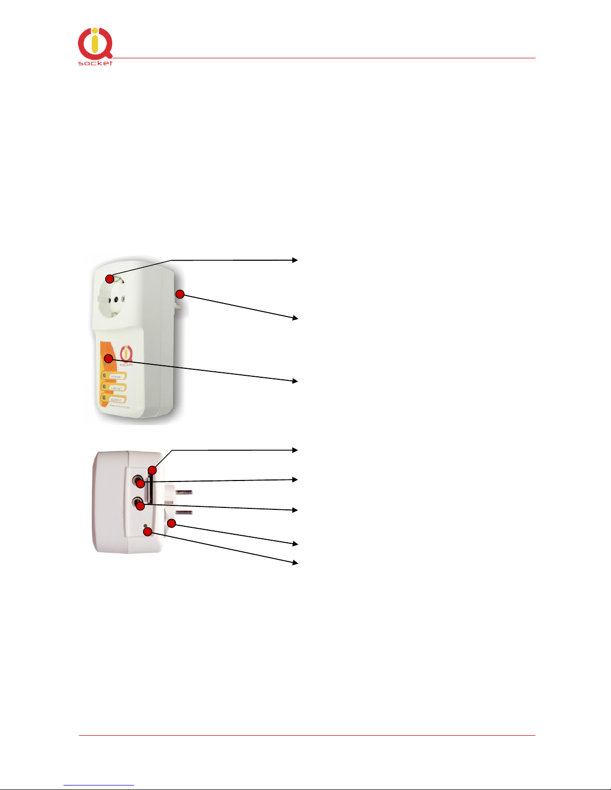
Output power socket: Connect your
electric appliance here. This socket is
intelligent, can be controlled remotely,
manually or automatically (scheduler).
Power plug: Input of AC power for
product and also for connected
appliance. Fits into electric
socket/outlet.
Microphone: For listening of sound
from surrounding environment.
SIM socket: Socket for SIM card.
Push-push type.
Input – Jack2: Opto-isolated input for
external sensors.
Output Jack1: Auxiliary independent
switched output, 30VDC/0.5A max.
Temperature sensor:
Push button: For turning on/ off
output power socket manually or
resetting configuration to factory
default values.
Besides controlling of the power, IQsocket IQSW-GSM is equipped with a choice
of useful functions, including:

©2011 IQtronic, Ltd
Page 5 of 34
Temperature sensor allows monitoring temperature among temperature
alarm and thermostat function
Alarm function using external sensors connected to input jack
Remote monitoring of the input state
Listening of sound from surrounding environment using integrated
microphone by call (tapping)
Sending SMS alert on power lost and restored, keeps log of last five power
lost events
Time scheduler function, allowing switching on/off your appliance based on
day of week and time.
2.1 Product features
In general, IQsocket IQSW-GSM has following features:
Controlling (turn on, turn off; turn on/off for a specified time; restart
by cutting power for short time) of any electric appliance connected to
the switched socket by SMS, by call or manually by pressing
pushbutton on IQSW-GSM body
Controlling (turn on, turn off; turn on/off for a specified time; restart
by cutting power for short time) of any electric appliance connected to
the microrelay output jack by SMS or by call.
Monitoring of temperature, temperature alarm and thermostat function
Switching on/off your appliance automatically using scheduler function,
based on day of week and time.
Sending informational status SMS messages to user upon request or
automatically on scheduled date/time
Providing status of switched socket by SMS upon SMS request
Sending SMS alarm alert on power loss and restore
Automatically stores up to last five power lost events in internal log
Input jack for connecting external sensors such as PIR, door contact,
gas leakage sensor and so on – status can be remotely monitored and
used to generate alarms
Internal real-time clock
Sending current values of user-configured IQSW-GSM parameters
upon SMS request
Configuring IQSW-GSM parameters simply by sending SMS commands
Listening of sound from surrounding environment using integrated
microphone by call (tapping)

©2011 IQtronic, Ltd
Page 6 of 34
3 Installation
Before starting installation, please read this manual and take into account
Important information section at beginning of this manual.
3.1 Inserting SIM Card
Prepare a standard size SIM card from your favorite GSM operator and insert it
into SIM bay of your IQsocket IQSW-GSM:
Insert SIM card into the SIM bay and
push it gently inside until you hear/feel
a click, so it becomes locked inside
bay.
To remove SIM from your IQsocket
IQSW-GSM, gently push the SIM inside
the bay until you feel and hear a click
again; card will become unlocked and
now pull it out of the bay.
WARNING!
PIN authorization should be turned off before the SIM card is
used in IQsocket IQSW-GSM
Authorization can be turned off by inserting the SIM card into a GSM phone and
disabling SIM PIN usage using appropriate command usually located in
„Settings‟ phone menu. Now you can remove the SIM card from phone and
insert it into your IQsocket IQSW-GSM.
©2011 IQtronic, Ltd
Page 7 of 34
Note…
It is highly recommended to delete all received SMS messages,
stored on the SIM card before using it in IQsocket IQSW-GSM
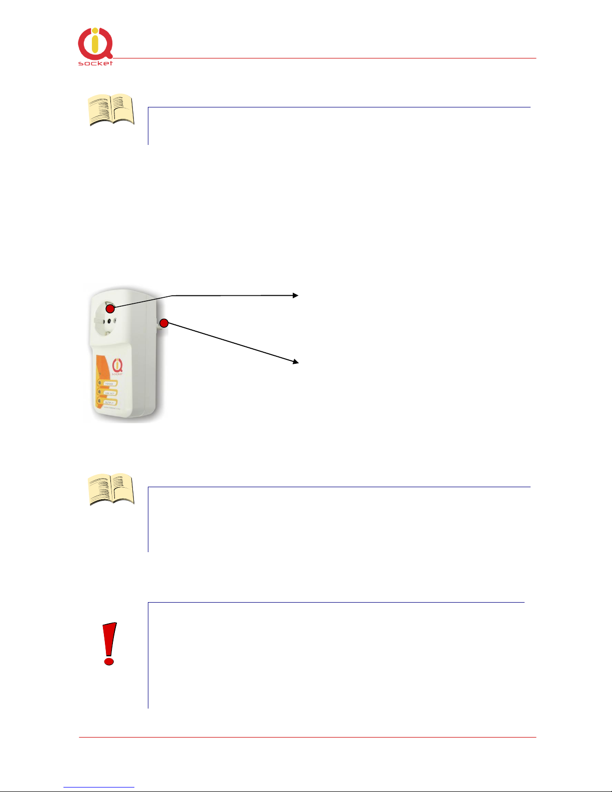
3.2 Wiring the IQsocket IQSW-GSM
Wiring is intuitive, simply connect your electric appliance into the device‟s
socket and plug the IQSW-GSM into a free power socket.
Controlled power socket: Connect
your electric appliance here.
Power plug: Plug the IQSW-GSM into
an electrical socket.
Note…
Both the socket and the plug of the IQSW-GSM follow the same
international standard and nominal voltage rating. Ensure you
ordered proper international version of the IQSW-GSM suitable
for your country
WARNING!
Please respect maximum rating 16A for switched socket and
30VDC/0.5A for the auxiliary microrelay output. Do not
overload your IQSW-GSM, as this may damage or shorten life
span of the internal switching relays, which is not covered by
warranty. It is recommended to use external contactors in case
of higher current is required and/or capacitive/inductive load
with high startup current needs to be switched.
©2011 IQtronic, Ltd
Page 8 of 34
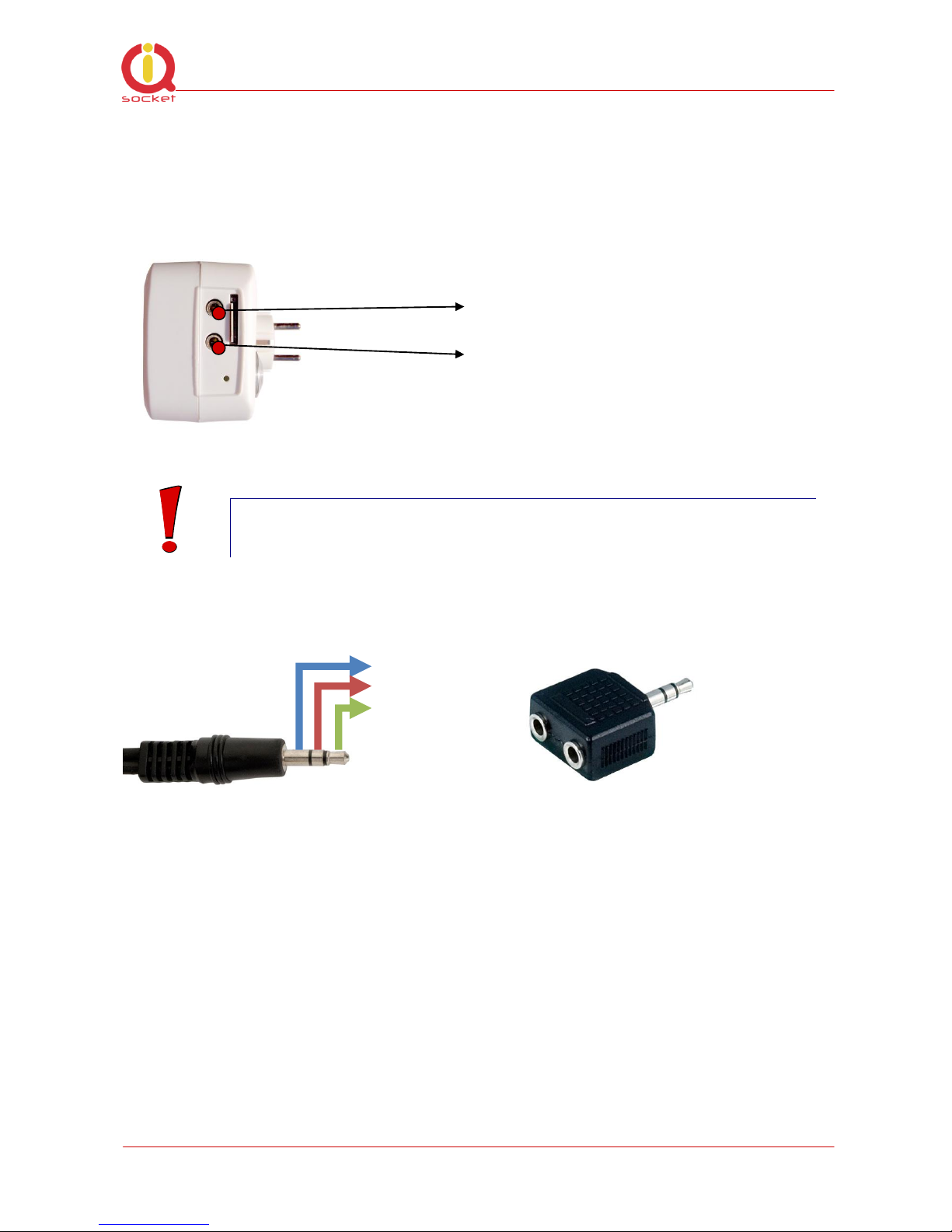
3.2.1 Using jack input and output
Both Output of auxiliary microrelay – the Jack1 and Input for external sensors
– the Jack2 use for connection a standard 3.5mm “stereo jack” (three pin)
sockets.
Input – Jack2: Opto-isolated input for
external sensors.
Output Jack1: Auxiliary independent
switched output, 30VDC/0.5A max.
WARNING!
Please ensure you do not exchange Input and Output
connections.
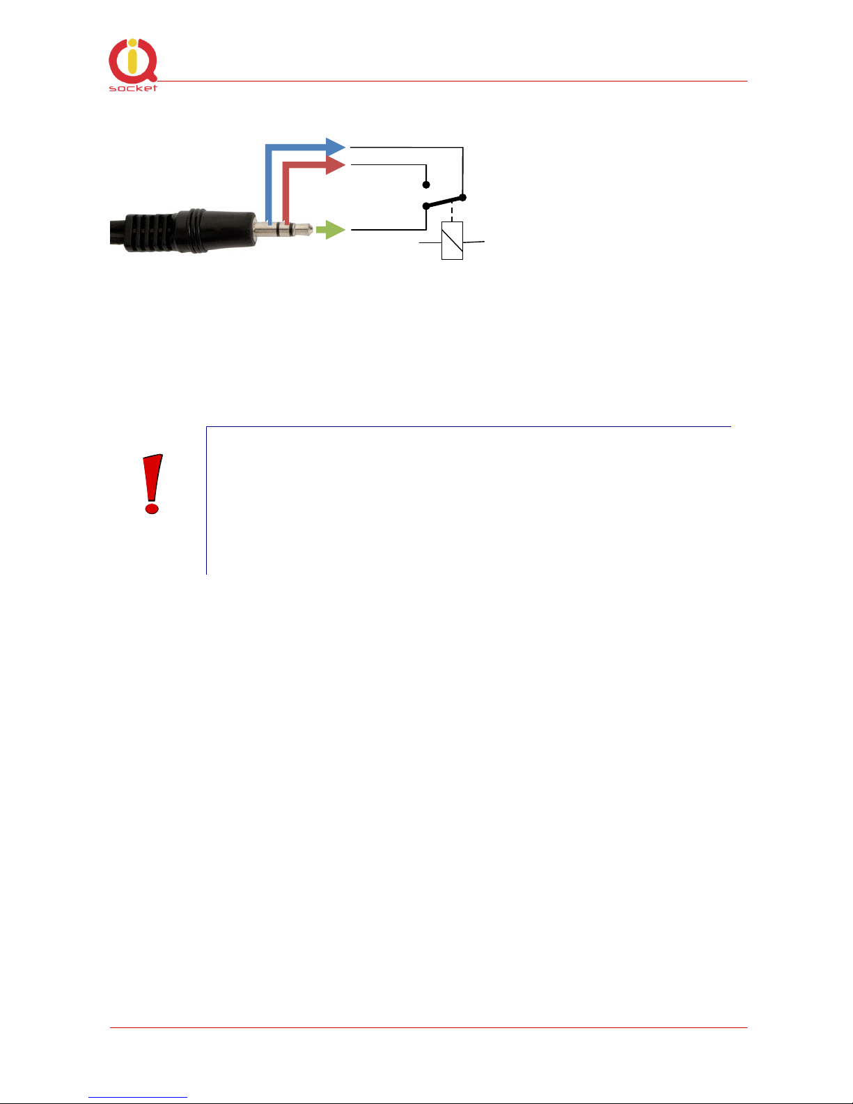
Jack1 - input
GND
Input
+5V/50mA
internally
fused
There is provided +5V/50mA power supply line for powering external sensors.
It is also possible to connect more than a single sensor to the IQSW-GSM, but
without identification of which particular sensor has invoked the change of the
input state/alarm. You can use a standard Y-adapter for this purpose. Please
note you must design wiring the way to perform a logical OR function since Yadapter provides parallel connection of the plugs.
See also chapter 4.10.3 with description of INPUTTYPE command.
Y-adapter
©2011 IQtronic, Ltd
Page 9 of 34
Jack2 - output
Input jack detects if there is a plug inserted into it, which is indicated by
the STATUS message and response to INPUTALARM command.
Output is provided in a form C/SPDT microrelay contact as shown in the
drawing – switch orientation is in position when the socket is in off state.
WARNING!
Please respect maximum rating of the auxiliary microrelay
output - 30VDC/0.5A. Do not overload your IQSW-GSM, as this
may damage or shorten life span of the internal switching
relays, which is not covered by warranty. It is recommended to
use external power relays/contactors in case of higher current
is required and/or capacitive/inductive load with high startup
current needs to be switched.

©2011 IQtronic, Ltd
Page 10 of 34
3.3 Powering IQSW-GSM On
Once you plug your IQsocket IQSW-GSM into a live electric socket, it become
powered on and starts operation.
You can verify it by observing status of the LEDs:
Once AC power is connected, all three LED indicators will blink shortly
and internal self-test is performed in about 10seconds. Then, if
everything is ok, the Power LED will turn to solid Red.
In case of active PIN authorization on the SIM card, GSM LED starts
blinking fast (approx. three times per second).
LINK/ACT (Green) starts to blink slowly (approx. every three seconds),
once device has been successfully logged into a GSM network. If the
LINK/ACT blinks about every second, searching of GSM network is in
progress.
The Output LED (Yellow) indicates state of output socket. Shining LED
means socket is active – appliance plugged into the output socket is
operating and vice versa. Blinking LED (approx. every two seconds)
indicates startup delay in progress - the output socket has been set to
on state but will be physically turned on after passing 30 seconds delay
since device startup.
Please see chapter 5 for more information on LED indicators.
Your IQSW-GSM is now ready for use.
4 Managing IQSW-GSM
This chapter guides you through management commands and features of
IQSW-GSM.
4.1 Managing by SMS
Commands are send in form of SMS messages to call number of SIM card
inserted into your device. Messages have following syntax:
pinCOMMAND (e.g. 3366STATUS)
o With pre-configured security password by command SMSPIN=3366

©2011 IQtronic, Ltd
Page 11 of 34
COMMAND (e.g. STATUS)
o with un-configured security password/SMSPIN
There are two kinds of commands:
Control commands (labeled as Ctrl in tables)
o Used to control of the IQSW-GSM and can be used at any time. Security
settings, such as SMSPIN, permitted callers list, DO apply.
Configuration commands (labeled as Cfg in tables)
o Allows to configure the IQSW-GSM parameters and functions. Security
settings, such as SMSPIN, permitted callers list, DO NOT apply – instead,
as a security measure, configuration commands are accepted only in
configuration mode.
o Configuration mode can be activated by using CONFIG command. Notice
CONFIG is a Ctrl-class command hence protected by your security
settings. Configuration mode is automatically deactivated after 10
minutes since last configuration command has been received.
o When a configuration command has been issued while configuration mode
is not active/already expired, error message “Timed Out!” will be replied
to the sender. See also chapters 4.7 and 0 for more information about
error messages.
Each command is normally confirmed by a response SMS sent back to the
command sender number. In case of an error is detected in a command,
IQSW-GSM will respond with error message to the sender. Sending response
and error SMS messages can be disabled. See also chapters 4.7 and 0 for
more information about error messages.
Case of commands is ignored; STATUS or sTaTUS is the same command.
All incoming SMS messages longer than 30 characters or messages containing
space and dot characters are being deleted without any error response.
SMS Command
Description
SMS Response
Type
TURNOFF
Turn the socket and the output off.
TurnedOff
Ctrl
TURNOFF1
Turn the socket off
TurnedOFF1
Ctrl
TURNOFF2
Turn the auxiliary output off
TurnedOFF2
Ctrl
TURNON
Turn the socket and the output on.
TurnedOn
Ctrl
TURNON1
Turn the socket on
TurnedON1
Ctrl
TURNON2
Turn the auxiliary output on
TurnedON2
Ctrl
TURNOFF=123
Turn the socket and the output off for
123 minutes.
TurnedOff 123 min
Ctrl
TURNOFF1=123
Turn the socket off for 123 minutes.
TurnedOff1 123 min
Ctrl
TURNOFF2=123
Turn the auxiliary output off for 123
minutes.
TurnedOff2 123 min
Ctrl
TURNON=123
Turn the socket and the auxiliary
output on for 123 minutes.
TurnedOn 123 min
Ctrl
 Loading...