

Page 1

GW-WIFI-01
IQRF WiFi Gateway
User’s Guide
© 2018 IQRF Tech s.r.o. www.iqrf.tech www.iqrf.org User_Guide_GW-WIFI-01_180511 Page 1
Page 2
GW-WIFI-01
Description
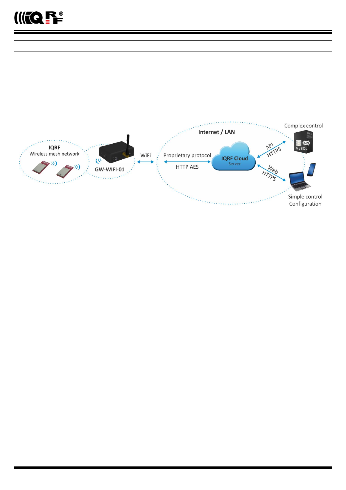
GW-WIFI-01 is an IQRF gateway for connection between
IQRF and WiFi networks allowing remote monitoring, data
collection and control of IQRF network.
The gateway communicates outside the IQRF network via
WiFi. Configuration is possible via internal www server, IQRF
IDE or SD card.
GW-WIFI-01 allows communication with IQRF IDE to
configure internal TR module and simply create an IQRF
network. It is fully compatible with the DPA protocol. NonDPA applications are supported as well.
Applications
Remote monitoring and control
Data acquisition / collection
Datalogger, IQRF Cloud supported
Interface to building / home automation
Connection of more IQRF networks to single PC
DPA as well as non-DPA applications supported
Key features
HTTP client for communication with IQRF Cloud server
HTTP server for remote management
UDP server/client for communication with IQRF network
DDNS support
SNTP client for getting date and time from Internet
DHCP server/client for automated getting of IP address
NBNS server for using names instead of IP addresses
RTCC (real time clock/calendar)
Firmware upgrade via web server / SD card
Upgrade of application in internal TR module via web
server / IQRF IDE / SD card
DPA and IQRF IDE compatible
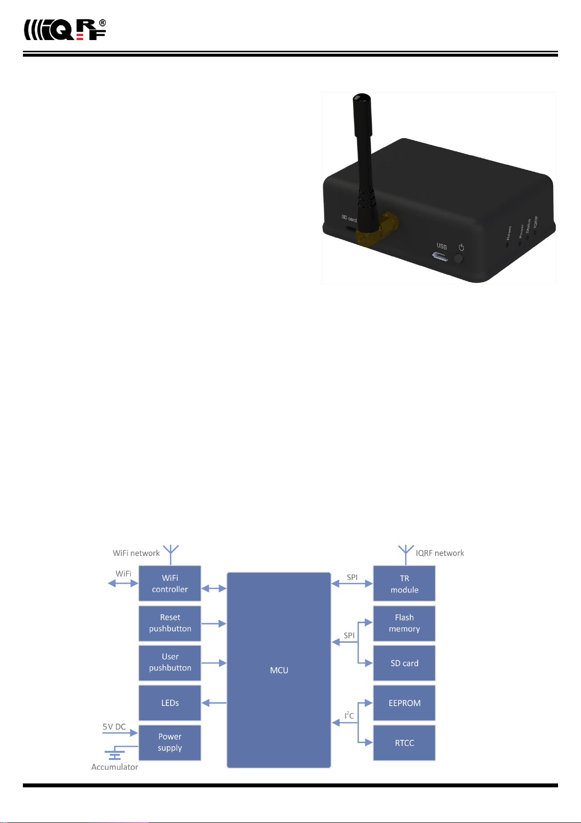
Block diagram
© 2018 IQRF Tech s.r.o. www.iqrf.tech www.iqrf.org User_Guide_GW-WIFI-01_180511 Page 2
Page 3

GW-WIFI-01
This gateway can be used either with TR as well as with DCTR transceivers. For simplicity, only TR is mainly used further on throughout
this document.
Information contained in this publication regarding device applications and the like is provided only for your convenience and may be
superseded by updates. It is your responsibility to ensure that your application meets with your specifications.
IQRF Tech MAKES NO REPRESENTATIONS OR WARRANTIES OF ANY KIND TO STATED CONDITION, QUALITY,
PERFORMANCE, MERCHANTABILITY OR FITNESS FOR PURPOSE and disclaims all liability arising from this information and its
use. Use of IQRF Tech devices in life support and/or safety applications is entirely at the buyer's risk, and the buyer agrees to defend,
indemnify and hold harmless IQRF Tech from any and all damages, claims, suits, or expenses resulting from such use. No licenses
are conveyed, implicitly or otherwise, under any IQRF Tech intellectual property rights.
Electrical specifications (Typical values unless otherwise stated)
Power supply 5.0 ± 0.35 V DC
Accumulator Li-Ion, 3.7 V, 700 mAh
Supply current
Off 6 µA
Sleep 85 mA
On 250 mA (not charging), 310 mA max. (charging)
Charge current 215 mA max.
Accumulator operating hours ~ 2 hours
Temperature range
Operating 0 °C to +60 °C
Storage 10 °C to +20 °C (recommended)
IQRF
Frequency bands 868 MHz or 916 MHz (SW configurable)
RF output power According to TR module, programmable in 8 steps
TR module (DC)TR-72DA or DCTR-52DA
Antenna PCB antenna built-in TR module
EEPROM 24AA16-I/MC, 16 Kb, 1 000 000 erase/write cycles min.
Flash memory SST25VF080B, 8 Mb, 100 000 erase/write cycles typ.
SD card Up to 2 GB
WiFi 802.11g
USB Custom class
Dimensions 87 mm x 62 mm x 26 mm
Weight 70 g
Absolute maximum ratings
Stresses above those values may cause permanent damage to the device. Exposure to maximum rating conditions for
extended periods may affect device reliability.
Supply voltage (VCC) 5.5 V
Storage temperature -20 °C to +60 °C
© 2018 IQRF Tech s.r.o. www.iqrf.tech www.iqrf.org User_Guide_GW-WIFI-01_180511 Page 3
Page 4
GW-WIFI-01
Hardware
Main components are: 32b microcontroller, WiFi module, EEPROM memory, serial Flash memory, SD memory card, IQRF
transceiver module with antenna and RTCC.
Power supply
GW-WIFI-01 should be supplied via standard micro USB connector by external stabilized 5 V DC, e.g. from the power source
delivered with the GW or from USB interface. The accumulator is shared for RTCC as well as other circuitry. It is intended
for backup supply only.
Power modes
On Operational mode. The GW is fully functional. If external power supply is connected, the accumulator is charged
(until being full). If external power supply is not connected, the GW is supplied from the accumulator. Complete GW
initialization is performed when switching to On mode (either from Off or Sleep).
Sleep Power saving mode. It is only available if external power supply is connected. TR as well as WiFi modules are disabled, no communication is possible. The accumulator is charged (until being full).
Off It is only available if external power supply is disconnected. Except of RTCC, all other circuitry is disconnected from
power supply and all other functionality is disabled. RTCC keeps running, powered from the accumulator. The
accumulator is not charged.
Switching over to another mode can be controlled by the Control pushbutton. See chapter Pushbuttons. Additionally, the GW
is switched Off automatically if accumulator voltage drops below 3.2 V (when supplied from the accumulator in On mode) or
if external power is disconnected in Sleep mode.
© 2018 IQRF Tech s.r.o. www.iqrf.tech www.iqrf.org User_Guide_GW-WIFI-01_180511 Page 4
Page 5

GW-WIFI-01
WiFi
2.4 GHz UHF band is used.
USB
USB interface enables an interconnection between the GW and a PC with IQRF IDE development software. It is intended for
uploading the application code into internal TR transceiver, debugging the application and GW configuration using the GW
Tool (a SW component of IQRF IDE for managing IQRF gateways).
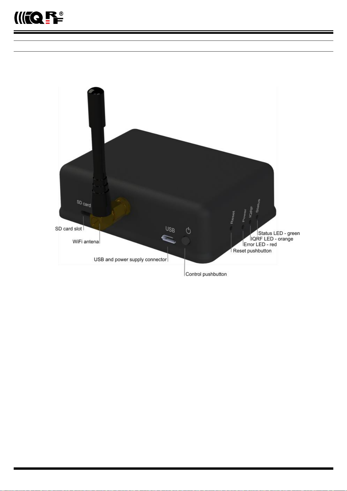
Pushbuttons
Both Reset and Control pushbutton functionality is fixed and can not be changed in application program.
Control
Short press (< 1 s): No effect
Long press (1 s to 10 s): GW off
Long press (> 10 s): Restore the factory settings of the gateway. (After 10 s all LEDs get off to indicate that the
factory setting was restored.)
Reset
Reset button can be pressed by a pin through the hole in the case. It is intended to reset the gateway (equally to switching
the GW off and on). Current GW configuration stays unchanged. For reinitializing the GW (to restore the factory settings),
use menu Maintenance › Factory Defaults at Web server or user pushbutton.
LEDs
See Appendix 1 – LED indication.
RF
(DC)TR-72DA or DCTR-52DA wireless transceiver module is used for IQRF connectivity. Antenna is built in TR module.
EEPROM
Internal serial EEPROM is intended to store the data for GW configuration. It is not available for user application SW.
Flash memory
Log data is stored in circular buffer in Flash memory. When it is full and a subsequent write is performed, then it starts
overwriting the oldest data.
There is 252 KB dedicated to IQRF RX data and 128 KB for IQRF TX data and same size for System log.
The number of records of IQRF RX/TX data depends on the parameter Packet size, which define how many payload data
bytes is dedicated for every data record. For default setting (Packet size = 64 B) there is 3308 positions for IQRF RX
and 1680 positions for IQRF TX. For System log there is always 6553 positions in the buffer.
The actual size of the data log is the Packet size + 14 B, where the additional 14 bytes are used for saving date, time
and index of the log. In this way the user can calculate actual number of positions in the buffer.
Data volumes and recording frequency must be taken in account with respect to the Flash memory endurance.
When the Packet size is changed in the GW settings, all logs are cleared.
Case
Caution: It is not allowed to open the GW case otherwise the device may be damaged.
© 2018 IQRF Tech s.r.o. www.iqrf.tech www.iqrf.org User_Guide_GW-WIFI-01_180511 Page 5
Page 6
GW-WIFI-01
Operation
Start up
GW-WIFI-01 is turned on by connecting a USB power supply or by pressing the Control button to be supplied from internal
accumulator (when no external power source is connected).
Initialization
After the start-up, the GW checks its own hardware first. If there is no critical error it starts to initialize WiFi connection. When
a critical error occurs, the execution does not continue and the error code is indicated by LEDs.
Communication
The size of payload IQRF data transmitted between the GW and the IQRF network is limited to 64 B in both directions.
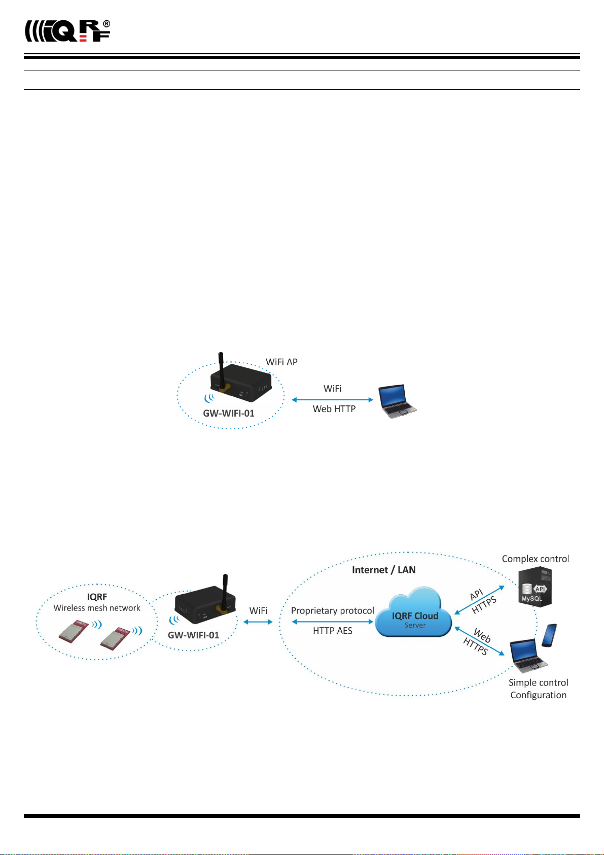
GW-WIFI-01 can work in the following modes:
WiFi Access point
Special service mode intended to WiFi interface configuration.
GW-WIFI-01 works in WiFi access point mode when it is started for the first time after delivering from the factory or after
restoring the factory defaults (by the Factory defaults pushbutton or via the web interface). Then, similarly as a WiFi router,
the GW allows to connect a WiFi device. This connection is only intended to configure the GW for subsequent operation, e.g.
selecting the operation mode (datalogger or gateway) and setting other GW parameters (selected WiFi network, passwords
etc.). After the configuration and restart the GW starts to work as a WiFi client and attempts to connect the WiFi network
specified in the configuration.
WiFi client - Datalogger mode
All incoming IQRF data (IQRF RX) is stored and logged in internal Flash memory. When used with IQRF Cloud, the logged
data is transmitted to the Cloud server always after the Cloud period elapsed. See chapters IQRF IDE – GW Tool and Web
server.
Data to be sent to IQRF (IQRF TX) is stored in internal Flash memory. When used with IQRF Cloud, the data is stored in the
Cloud server first, transferred to the GW always after the Cloud period elapsed and then forwarded to IQRF network.
If the communication between the GW and the Cloud server failed, the GW indicates an error.
© 2018 IQRF Tech s.r.o. www.iqrf.tech www.iqrf.org User_Guide_GW-WIFI-01_180511 Page 6
Page 7
GW-WIFI-01
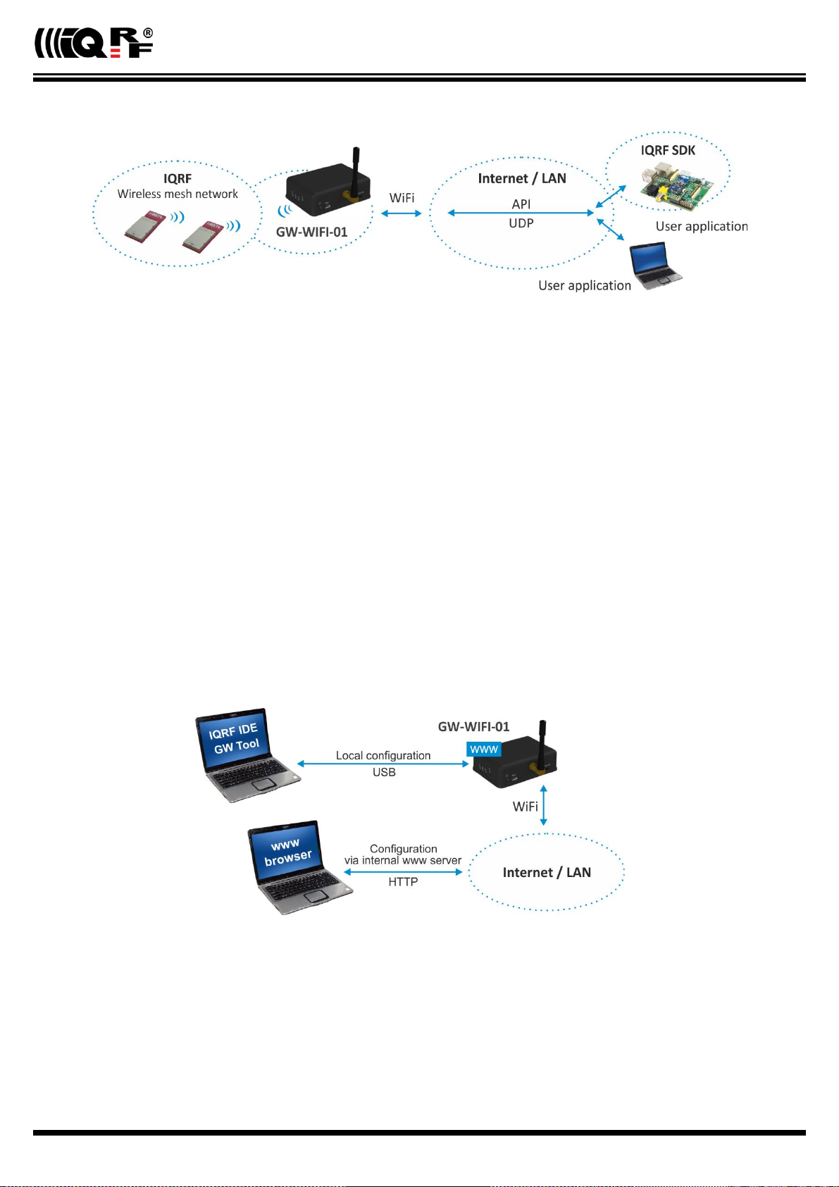
WiFi client – Gateway mode
Direct connection between IQRF networks and remote device via UDP channel is established.
The communication uses a specific application protocol, see chapter Application protocol for UDP channel.
Errors in communication between the GW and the remote device should be solved by the user application.
Using IQRF IDE
The IQRF IDE GW Tool is intended for GW configuration, checking of operational and error states and for access to the
datalogger. When using the GW Tool, the communication via WiFi is enabled.
Additionally, IQRF IDE can be used similarly as for the CK-USB-04(A): uploading the code into TR transceiver, configuration
of TR module inside the GW (including Access password and User key, see IQRF OS v4.xx User’s guide, chapter Encryption),
debugging of the application, using the IQMESH Network manager etc. In this mode the communication via Ethernet is
disabled.
Internal web server
To get connected to the internal web server, it is necessary to know IP address of the GW or the GW host name (if the
network supports the NBNS, i.e. within the LAN only). Internal web server is used for GW configuration (manually in graphic
environment or by loading a binary file *.gwcnfg), TR programming (*.hex, *.iqrf), TR configuration (*.trcnfg,
excluding Access password and User key for encryption) and FW upgrading (gwwifi.hex). When uploading any of these
files, it is necessary to have SD card plugged in the GW card slot, otherwise the operation can not be completed.
GW configuration
GW configuration is possible via internal www server, IQRF IDE or (especially for troubleshooting) via SD card.
© 2018 IQRF Tech s.r.o. www.iqrf.tech www.iqrf.org User_Guide_GW-WIFI-01_180511 Page 7
Page 8

GW-WIFI-01
SD card file structure
The SD card is intended for development, service and maintenance. It should be accessed primarily by the GW while direct
writing by the user (externally by a standard SD card reader/writer) is recommended for exceptional purposes only. The
standard way to perform required changes is using the internal web server.
The SD card uses the following folders:
Root The root directory is intended for a new FW (gwwifi.hex file) to be used for upgrade.
TRUPLOAD The folder intended for files to be uploaded into the TR module (*.hex, *.iqrf, *.trcnfg).
GWCNFG The folder intended to record a new GW configuration (*.gwcnfg).
BACKUP The folder intended for current GW configuration (gw.gwcnfg).
When using the web server, all folders and files are created automatically when required. In case of external direct writing
the required folders must be created by the user. Files not necessary any more are automatically deleted after the usage.
System log
All important events are logged. System logs can be read using IQRF IDE GW Tool.
Date and time
GW-WIFI-01 contains a real time clock/calendar (RTCC). Date and time are synchronized using SNTP/Cloud server.
TR module data exchange
Data between the internal TR module and the GW memory is transferred bidirectionally via SPI (using the bufferCOM
memory array inside the TR module). Therefore, the application in TR must have the SPI communication activated. When
using DPA, a hardware profile with SPI interface must be uploaded in TR. Such plug-in is uploaded from the factory. The
maximum SPI packet length is 64 B.
LAN services
HTTP client Communication with IQRF Cloud server (using 128 b AES encryption)
HTTP server Web pages for remote management via a common browser
HTTP client Getting and updating of public address from DDNS
UDP server/client Communication with IQRF network and for remote GW management
SNTP client Getting date and time from time server
ICMP server Allowing “ping” to GW from a remote host
DHCP server For IP addresses dedicated to one client (when the GW works in Access point mode)
DHCP client Automated getting of IP address from the DHCP server
NBNS server For using names instead of IP addresses within the LAN
© 2018 IQRF Tech s.r.o. www.iqrf.tech www.iqrf.org User_Guide_GW-WIFI-01_180511 Page 8
Page 9

GW-WIFI-01
GW identification
MAC address
Every device has a unique MAC address in the format 00 1F D5 xx xx xx, where:
00 1F D5 is the OUI dedicated to MICRORISC s.r.o.
xx xx xx is a device serial number
Actual MAC address is printed on the label at the bottom of the GW-WIFI-01 case.
ID
Another unique number (manufacturer's identification) used to identify the gateway by IQRF IDE, the IQRF Cloud server and
user applications utilizing the Cloud via API.
For GW-WIFI-01: ID = 10 xx xx xx, where xx xx xx are last 6 digits of the MAC address.
NBNS Name
iqrf-xxxx, where xxxx are the last 4 digits of the MAC address.
© 2018 IQRF Tech s.r.o. www.iqrf.tech www.iqrf.org User_Guide_GW-WIFI-01_180511 Page 9
Page 10
GW-WIFI-01
IQRF Cloud
The IQRF Cloud provides an effective way to exchange data between IQRF wireless device(s) and a user superordinary
system implemented by a higher level platform (e.g. PHP, JavaScript or web interface) and connected via Internet or a LAN.
As an interface to IQRF, the GW-WIFI-01 or another IQRF gateway providing Internet connectivity (Ethernet, GPRS or WiFi)
is intended.
An IQRF Cloud server is available on http(s)://cloud.iqrf.org provided by CIS (Complete Internet Services, s.r.o.,
an IQRF contractual partner for cloud solutions). Moreover, a licensed version is available for every user of an IQRF gateway
preferring to implement and operate one's own IQRF Cloud. Refer to the IQRF Cloud User's Guide for details.
© 2018 IQRF Tech s.r.o. www.iqrf.tech www.iqrf.org User_Guide_GW-WIFI-01_180511 Page 10
Page 11

GW-WIFI-01
IQRF IDE – GW Tool
IQRF IDE 4.20 and higher is required.
Login to GW Tool
The GW Tool can be invoked from IQRF IDE menu Tools → GW Tool.
To open the Tool, the username and the password must be entered. Default values are iqrf and iqrf.
Status
The Status tab contains general overview about the gateway status. Several buttons are available to control the GW:
Copy ID To copy the GW ID to the clipboard
Restart To restart the gateway
Update To update the Status tab
Close To close the GW Tool window
© 2018 IQRF Tech s.r.o. www.iqrf.tech www.iqrf.org User_Guide_GW-WIFI-01_180511 Page 11
Page 12

GW-WIFI-01
Device information
Type Current GW type
Host name Name identification of GW in Ethernet network (used by NBNS)
MAC address Globally unique identification of GW – Ethernet interface
ID Unique identification number of the gateway, provided by the factory
Firmware ver. Current firmware version
TR module
Type The type of IQRF TR module inside the gateway
FCC ID FCC certification identification
MID Unique IQRF TR module identification number
OS IQRF OS version (and OS build) of TR module
WLAN information
WLAN type Displays the mode which the GW currently works in
Access point The default set by the factory. It is intended for the first configuration of the GW.
Client Standard operation mode
SSID name For Client mode: SSID of the WiFi network which the GW is connected to (or is attempting to
connect.
For Access point mode: SSID of the WiFi network created by the GW
Security type Mode of WiFi network security
Open
WEP
WPA / WPA2
RSSI WiFi signal strength
LAN information
IP address Current IP address of the GW
Subnet mask Ethernet network address range
Gateway Main gateway/server of the Ethernet network
Primary DNS Primary server with DNS service
Secondary DNS Secondary server with DNS service
© 2018 IQRF Tech s.r.o. www.iqrf.tech www.iqrf.org User_Guide_GW-WIFI-01_180511 Page 12
Page 13

GW-WIFI-01
System status
GW status Current operation executed by the gateway:
Communication
Cloud Server Communication
Error
GW error An error during execution indication:
No Error
TR SPI Error
LAN Error
Cloud Server Error
SD Card Error
WLAN status
Connected GW is connected to selected WiFi network
Disconnected GW is not connected to selected WiFi network (the connection is lost or has never been
established at all)
Power Currently used power supply
External
Accumulator
Accu voltage Actual voltage of internal accumulator
Current Date/Time The date and time used in the gateway
© 2018 IQRF Tech s.r.o. www.iqrf.tech www.iqrf.org User_Guide_GW-WIFI-01_180511 Page 13
Page 14

GW-WIFI-01
WLAN
The following buttons are available in addition to previous ones:
Default To restore the default configuration
Download To read the configuration from GW
Upload To store the configuration to GW
Mode
Specifies the operation mode of WiFi module inside the GW
Client Standard operation mode of the GW. In this mode, the GW is connected to the WiFi network according
the parameters specified in the Connection section.
Access point Intended for initial GW configuration. The default mode preselected from the factory.
Connection
Intended for setting of parameters of WiFi network which the GW is connecting to or which is creating by the GW.
SSID name SSID of WiFi network which the GW is connected to
Security type WiFi network security mode
Open Not protected network
WEP 64 b Network protected by the WEP security protocol
WEP 128 b
WPA / WPA2 Network protected by the WPA or WPA2 security protocol
Key type The format of the key for the WEP type protection.
HEX In hexadecimal
ASCII ASCII characters
Key To specify the security key allowing to connect the selected WiFi network
Select The button to check available WiFi networks
© 2018 IQRF Tech s.r.o. www.iqrf.tech www.iqrf.org User_Guide_GW-WIFI-01_180511 Page 14
Page 15

GW-WIFI-01
This window displays available WiFi networks, their SSIDs, protection types and signal strengths. Select the desired network
by the mouse and click the button Select. Parameters of selected network will then be updated in the Connection section
(see the figure above). Then the access key must be entered there.
The Scan button starts searching the available WiFi networks.
The number of detected networks is successively displayed at Number of found networks line. The searching can be
terminated by the Stop button.
© 2018 IQRF Tech s.r.o. www.iqrf.tech www.iqrf.org User_Guide_GW-WIFI-01_180511 Page 15
Page 16

GW-WIFI-01
LAN
LAN
It allows to set/get the parameters relating to Ethernet connection.
Host name Name identification of GW in the Ethernet network (used by NBNS). If the main
gateway/server offers NBNS service, it is allowed to use this host name instead
IP address of GW.
Obtain automatically (DHCP) If the main gateway/server offers DHCP service, it is allowed to get all LAN parameters
automatically (IP address, Subnet mask, Gateway, Primary DNS, Secondary DNS)
IP address Current IP of the GW
Subnet mask Ethernet network address range
Gateway Main gateway/server of the Ethernet network
Primary DNS Primary server with DNS service
Secondary DNS Secondary server with DNS service
© 2018 IQRF Tech s.r.o. www.iqrf.tech www.iqrf.org User_Guide_GW-WIFI-01_180511 Page 16
Page 17

GW-WIFI-01
DDNS
DDNS service allows to get public address of network which the GW is assigned in. GW communicates with the DDNS server
in checking interval and transmits its current IP address.
For IQRF DNS:
The user or user application reads the IP address from the service provider server using the ID of the GW.
For other DDNS servers:
The user or user application accesses the GW using the Host Name. Refer to the website of given server.
DDNS DDNS service activation
Service provider List of supported DDNS servers
Host name Name identification of GW within DDNS
User name DDNS account username
Password DDNS account password
Check Interval Communication period between the GW and DDNS server
Operation Mode
The Operation mode tab provides the setting of the gateway.
Mode
Datalogger The datalogger is active. Its content can be read using IQRF Cloud server (if enabled), or IQRF IDE
GW Tool.
Gateway UDP channel is active. It is direct connection to the GW (without IQRF Cloud) using the application
protocol described in chapter Application protocol.
Communication ports can be selected in the Gateway field - Port and Remote port.
Logger
Packet Size The size dedicated for the data log in the gateway memory. By default, this value is set to 64 B, the same
as the maximum size of the IQRF packet. Shorter packets allow to store more data logs. Minimum packet
size is 1 B. When an IQRF packet oversizes the selected packet size, a part of user data is lost.
When the packet size is changed the content of internal memory is cleared.
© 2018 IQRF Tech s.r.o. www.iqrf.tech www.iqrf.org User_Guide_GW-WIFI-01_180511 Page 17
Page 18

GW-WIFI-01
IQRF Cloud
Period Defines how often the gateway transmits the data to IQRF Cloud server. Allowed
values are from 2 s to 24 hours.
Use IQRF Cloud hosted by CIS The gateway is configured by default to communicate with IQRF Cloud server
provided by CIS. Any gateway can also communicate with another IQRF Cloud
server provided by anyone else. In such a case, the checkbox must be unchecked
and the following fields must be filled.
AES key Encryption key used for secure communication between the gateway and the IQRF
Cloud server. The same key must also be specified at the server side.
Cloud path The URL address where IQRF Cloud server is hosted. The '/cloud' substring
must follow.
Cloud port The TCP port used. In most cases port 80 is used.
Gateway
GW Port UDP port for the GW side.
Remote port UDP port for a remote device side.
Time
GW time and date setup.
Set time
Manual To setup the time manually
PC time To upload the date and time from connected PC.
Selected time is transferred to the GW by the Set Time button.
© 2018 IQRF Tech s.r.o. www.iqrf.tech www.iqrf.org User_Guide_GW-WIFI-01_180511 Page 18
Page 19

GW-WIFI-01
GW time
Current GW Date/Time Date and time currently running in the GW
Time zone Time zone selection
Use daylight savings Daylight savings for given time zone selection
Use SNTP server When activated, the GW time will be synchronized with specified SNTP server time once
per 6 hours.
Server SNTP server selection. IQRF Cloud server is also available for this.
Administration
The user can change the username and the gateway password here. When the password is changed, in order to allow an
access the data on the Cloud server it must be changed there too. The change of username has no effect for that. Allowed
password length is from 4 to 8 characters. When the username or the password is lost, the user can reset the gateway to
factory settings. The default username and password values are iqrf and iqrf.
Password
A standard way to change the GW password.
HTTP Server
Disable remote management Internal web server inside the GW can be disabled. The change takes effect after
GW reset. The configuration through IQRF IDE – GW Tool is possible even if this
option is disabled.
© 2018 IQRF Tech s.r.o. www.iqrf.tech www.iqrf.org User_Guide_GW-WIFI-01_180511 Page 19
Page 20

GW-WIFI-01
GW_OFF_BY_BTN
CLOUD_LICENSE_DONE
GW_OFF_BY_LOW_ACCU
CLOUD_CONNECTION_ERROR
GW_ON_BY_BUTTON
CLOUD_REGISTRATION_ERROR
GW_ON_BY_EXT_POWER_ON
CLOUD_UPLOAD_ERROR
GW_RESET
CLOUD_DOWNLOAD_ERROR
GW_RESET_FOR_NEW_SETTINGS
CLOUD_DOWNLOAD_CONF_ERROR
GW_RESET_FOR_FIRMWARE_UPGRADE
CLOUD_SYSTEM_PACKET_ERROR
GW_LAN_ERROR
CLOUD_UNKNOWN_PACKET_RECEIVED
SD_CARD_ERROR
CLOUD_LICENSE_ERROR
CLOUD_REGISTRATION_DONE
TR_SPI_ERROR
Log
Transmitted data stored on the Cloud server stays also accessible directly in the GW buffer.
Buttons:
Restart To restart the GW
Erase Log To erase the content of the whole GW internal log memory
Update To read the data from the GW and refresh the Log window
Close To close the GW Tool window
Three types of logs are stored in the gateway:
IQRF Rx Data received from IQRF network and transmitted to the Cloud server
IQRF Tx Data downloaded from Cloud server and transmitted to IQRF network
System Certain events that occurs during the execution. The user do not usually need to take care about it.
Nevertheless it can be helpful in case of nonstandard behavior.
Last Record When selected, the output list is scrolled down to display the last acquired data.
The format of IQRF RX/TX data depends on the user application in TR (e.g. DPA or any user-specific protocol). The format
of system log is fixed.
The following system events are logged:
© 2018 IQRF Tech s.r.o. www.iqrf.tech www.iqrf.org User_Guide_GW-WIFI-01_180511 Page 20
Page 21

GW-WIFI-01
Web server
The web server inside the GW is primarily intended for GW configuration.
Default GW settings predefined by the factory is
Access point mode and WiFi network with
SSID = IQRF-xxx, where xxxx are the last 4
characters of MAC address of the GW. This
network is not secured. After connection it is
possible to accomplish required configuration via
internal web interface.
To access the web server, the IP address of given
GW must be known. When accessing from a local
network, the domain name 'iqrf-xxxx' (where
xxxx are last 4 digits of the MAC address) can be
used instead of the IP address. Both GW user
name and the GW password are preset to 'iqrf' from the factory. Every page of the web server has a help.
It is recommended to change the user name and it is required to change the GW password as soon as possible, just after
the first login to the web server.
Web server can be enabled/disabled in IQRF IDE GW Tool / Administration.
Menu
The main menu provides an access to the configuration pages of GW.
Status Information about the device, current network connection
and the GW status.
WiFi Setup Selecting and setup the WiFi network for connection of the
GW as a client. Setup of registration parameters for this
network.
LAN Setup To select the network connection parameters.
Operation Mode To select the GW mode.
Dynamic DNS To configure Dynamic DDNS service used to find the public
IP address of the GW.
Password To change the access parameters for the Web server, Cloud
server and IQRF IDE.
Time To set the time and date manually or to activate automatic
time synchronization with the selected time server.
Maintenance For fundamental changes in GW and internal TR
functionality.
© 2018 IQRF Tech s.r.o. www.iqrf.tech www.iqrf.org User_Guide_GW-WIFI-01_180511 Page 21
Page 22

GW-WIFI-01
Status
Device information
Type GW type
Host Name Name identification within local network (using this name instead of IP address), in the networks
where NBNS is supported
MAC Address Globally unique identification of GW device within Ethernet networks
ID Unique identification of the gateway within the IQRF Tech product line
Firmware Version Current firmware version (including the build date)
WiFi information
Mode Current GW mode
SSID Name For Client mode: SSID of WiFi network which the GW is connected to (or is attempting to connect)
For Access point mode: SSID of the WiFi network created by the GW
Security Type WiFi network security mode
LAN information
The network connection parameters set manually or obtained through DHCP.
TR module
Type TR module type inside the GW
MID Unique IQRF TR module identification number
OS Current version of IQRF OS (and build version) of TR module
Status The state of the TR module
© 2018 IQRF Tech s.r.o. www.iqrf.tech www.iqrf.org User_Guide_GW-WIFI-01_180511 Page 22
Page 23

GW-WIFI-01
System status
GW Status Current operation executed by the gateway. See chapter System status above.
GW Error: Indicates whether there is an error during execution
Power Power supply type
Accu Voltage Not intended for GW-WIFI-01
Current Date/Time Current time of RTCC inside the GW
WiFi setup
GW-WIFI-01 WiFi interface configuration.
There are two possibilities to connect WiFi to the GW:
1. By the Scan Networks button: Select a connection from the list of available WiFi networks
If the WiFi network is secured, the access key must be entered.
Then configuration parameters are stored, the GW is restarted and then automatically attempts to connect selected WiFi
network.
© 2018 IQRF Tech s.r.o. www.iqrf.tech www.iqrf.org User_Guide_GW-WIFI-01_180511 Page 23
Page 24

GW-WIFI-01
2. By the Manual Configuration button:
Operation mode of WiFi module inside the GW can also be configured manually. Two modes are available:
Client Standard operation mode. GW is connected to given WiFi network.
Access point For initial GW configuration. This is the default preselected from the factory.
In Access point mode, the GW creates a WiFi network with SSID = IQRF-xxx, where xxxx are the last 4 characters of
MAC address of the GW. This network is not secured. After connection it is possible to accomplish required configuration
via internal web interface.
SSID name SSID of WiFi network to be used to connect the GW
Security Type WiFi network security mode
Open Not secured network
WEP Network protected by the WEP security protocol
WPA / WPA2 Network protected by the WPA or WPA2 security protocol
Selected configuration should be saved by the Save button. If the WiFi network is secured, the access key must be
entered.
Then configuration parameters are stored, the GW is restarted and then automatically attempts to connect selected WiFi
network.
© 2018 IQRF Tech s.r.o. www.iqrf.tech www.iqrf.org User_Guide_GW-WIFI-01_180511 Page 24
Page 25

GW-WIFI-01
LAN setup
On this page it is possible to change the name (Host Name) for access to the GW which can be used within a local network
instead of the IP address. If the DHCP service is available in the network, the Obtain automatically checkbox should be
activated, otherwise the parameters for access to the LAN network must be selected manually.
In the factory settings, these parameters are obtained automatically from the network using DHCP.
© 2018 IQRF Tech s.r.o. www.iqrf.tech www.iqrf.org User_Guide_GW-WIFI-01_180511 Page 25
Page 26

Operation mode
GW-WIFI-01
Mode
Datalogger Activates storing data from IQRF network. This data can be read by the Cloud server (if the
communication with the Cloud server is enabled) or using IQRF IDE. This is the default mode
preselected from the factory.
Gateway Enables communication via UDP channel between the GW and a remote system according to the
documented application protocol.
Packet Size The size of the user data in IQRF packets. By selecting a smaller value is possible to store a
larger number of packets. If the actual IQRF packet is longer, the remaining data is not saved.
IQRF Cloud Enabled Activates the communication with the Cloud server
Period Communication period which GW uploads/downloads data to/from the Cloud server in. Every digit
of the double-figure number is set separately.
Use IQRF Cloud hosted by CIS Allows to utilize the ready-to-use IQRF Cloud server hosted by CIS.
AES key Encryption key used for the first connection to the Cloud server
Cloud Path The URL address where IQRF Cloud server is hosted. The '/cloud' substring must follow
Cloud Port The TCP port used. In most cases port 80 is used.
GW Port UDP port for the GW side.
Remote port UDP port for a remote device side.
Save The button to confirm changes and close the window.
© 2018 IQRF Tech s.r.o. www.iqrf.tech www.iqrf.org User_Guide_GW-WIFI-01_180511 Page 26
Page 27

GW-WIFI-01
Dynamic DNS
Active Dynamic DNS Activates the GW - DDNS server communication. In the factory settings the DDNS is inactive.
Service Provider DDNS service provider selection
Host Name Name identification of the GW within DDNS
User Name Username for DDNS account
Password Password for DDNS account
Check Interval Communication period between the GW and the Service provider server (in minutes).
Minimum value is 10 minutes.
Password
Both User name and the Password are default preset to "iqrf" from the factory. The password should be changed by the
user on the Password Setup page. To accomplish the change, the original password and the new one must be entered. For
security, the new password must be typed two times.
When the password is forgotten, the factory settings of the GW must be restored by the Control pushbutton (see chapter
Pushbuttons above). Then the factory preset User name and Password are restored.
© 2018 IQRF Tech s.r.o. www.iqrf.tech www.iqrf.org User_Guide_GW-WIFI-01_180511 Page 27
Page 28

GW-WIFI-01
Time
The Time Setup allows to set the time of the internal clock measured by the GW. The time is required especially for the
datalogger. Individual logs are provided with time stamps. The time can be setup manually or via the SNTP service. The
SNTP provides periodical time synchronization from one of selected time servers. As a time server, the IQRF Cloud server
can be used as well. In the factory settings the time and date are synchronized with the IQRF Cloud server.
Maintenance
Main Menu returns from the Maintenance page to main menu.
Factory Defaults allows to restore the original factory settings or reboot the gateway.
Configuration page allows to write / read the GW configuration binary file *.gwcnfg.
TR upload To program the TR module.
FW upgrade Allows to upload a new firmware.
© 2018 IQRF Tech s.r.o. www.iqrf.tech www.iqrf.org User_Guide_GW-WIFI-01_180511 Page 28
Page 29

GW-WIFI-01
Factory Defaults
Restore factory defaults + Reboot Restores the GW settings to values preconfigured by the GW manufacturer and
reboots the GW.
Reboot only Reboots the GW (keeping the current GW configuration).
Execute Launches the operation selected above.
Configuration
This page allows to upload the binary configuration file *.gwcnfg or generate this file based on current GW settings. This
type of file can be also generated by IQRF IDE GW Tool.
TR upload
This page allows to reprogram the TR module inside the GW. Supported files are *.hex, *.iqrf and *.trcnfg.
*.trcnfg can be generated by export of TR configuration in IQRF IDE, but excluding Access password and User key
for encryption, which is allowed to be configured only locally, see chapter Using IQRF IDE.
FW Upgrade
This page allows to upgrade the GW by a new firmware (file gwwifi.hex) which may be released by IQRF manufacturer
and available on the product web page. See chapter FW upgrade – Bootloader below.
© 2018 IQRF Tech s.r.o. www.iqrf.tech www.iqrf.org User_Guide_GW-WIFI-01_180511 Page 29
Page 30

GW-WIFI-01
Factory setup
This initial setup can be restored whenever the control button is pressed for more than 10 s. This can be useful if it is not
possible to establish communication due to wrong configuration.
WLAN --------------------------------------------------------------------------------------------------------------------------------------------------
WiFi mode Access point
SSID name „IQRF-xxxx“, where xxxx are last 4 digits of the MAC address.
Security type Open
LAN ------------------------------------------------------------------------------------------------------------------------------------------------------
NBNS name „iqrf-xxxx“, where xxxx are last 4 digits of the MAC address.
Get IP address from DHCP server automatically On *
DHCP server On **
IP address 192.168.0.254
Subnet mask 255.255.255.0
Gateway 192.168.0.1
Primary DNS server: 192.168.0.1
Secondary DNS server 0.0.0.0
Operation Mode ---------------------------------------------------------------------------------------------------------------------------------------
Mode Datalogger
Packet Size 64B
IQRF Cloud Communication Enabled
Use IQRF Cloud Server hosted by CIS Enabled
Communication period 10 s
GW port for the application protocol 55300
Host port for the application protocol 55000
Dynamic DDNS ---------------------------------------------------------------------------------------------------------------------------------------
Dynamic DNS Disabled
Password ----------------------------------------------------------------------------------------------------------------------------------------------
Authorization when enter the internal web server page, IQRF Cloud server or IQRF IDE GW Tool
Username „iqrf“
Password „iqrf“
Time -----------------------------------------------------------------------------------------------------------------------------------------------------
Getting date and time from the time server On
Time server IQRF Cloud server
Summer / winter time distinguishing On
Time zone GMT+01:00
HTTP Server -------------------------------------------------------------------------------------------------------------------------------------------
Disable remote management Off
* When the GW is configured in Access point WiFi mode, IP addresses are preset in the default factory settings (getting IP
address from other DHCP server is off).
** When the GW is configured in Client mode, DHCP server is automatically off.
© 2018 IQRF Tech s.r.o. www.iqrf.tech www.iqrf.org User_Guide_GW-WIFI-01_180511 Page 30
Page 31

GW-WIFI-01
First startup
Factory settings
GW-WIFI-01 is set from the factory as follows:
WiFi mode Access point
SSID name „IQRF-xxxx“, where xxxx are last 4 digits of the MAC address.
Security type Open
User name “iqrf”
Password “iqrf”
Operation mode Datalogger
IQRF Cloud Enabled
IQRF Cloud hosting By CIS (https://cloud.iqrf.org)
Communication period 10 s
To enable IQRF Cloud services, the WiFi network must be configured at GW-WIFI-01 allowing Internet access and then
optionally an access to Cloud server. This can be accomplished by IQRF IDE via USB interface or via internal web interface.
For more information refer to chapters WLAN (for IQRF IDE) or WiFi setup (for web server) above.
When WiFi network is configured and GW establishes Internet connection, this setting can be used to operate the GW with
IQRF Cloud without any changes in configuration. But it is strictly recommended to change the GW password to avoid illegal
access to GW data.
Step by step guide
To get familiar with GW-WIFI-01 functionality, the GW can be used with DPA hardware profile in similar way as which is
described in IQRF DPA Quick Start Guide:
Follow this Guide, chapters 1 to 5.
Use GW-WIFI-01 instead of CK-USB-04(A)
GW-WIFI-01 is delivered with the (General)HWP-Coordinator-STD-SPI plug-in uploaded in internal TR transceiver.
Thus, there is no need to upload any HWP plug-in.
After LED control testing from IQRF IDE via USB according to chapter 5 mentioned above, test the same commands via
Ethernet:
Disconnect the GW from IQRF IDE.
Open the https://cloud.iqf.org page in web browser.
© 2018 IQRF Tech s.r.o. www.iqrf.tech www.iqrf.org User_Guide_GW-WIFI-01_180511 Page 31
Page 32

Create your user account there and login to this.
GW-WIFI-01
Add the GW to the List of gateways assigned to your account by the Add gateway button. The GW ID and the password
must be entered.
Open the main page of the GW by clicking to the GW ID number.
Click the Send data to IQRF button. The window with predefined LED control commands opens.
Using the macros or by modification of commands in IQRF Tx field and the Send button you can control LEDs in
individual or all nodes similarly as before (by using IQRF IDE).
© 2018 IQRF Tech s.r.o. www.iqrf.tech www.iqrf.org User_Guide_GW-WIFI-01_180511 Page 32
Page 33

GW-WIFI-01
Application protocol for UDP channel
UDP protocol is described in separate document IQRF UDP Technical guide.
IQRF DNS
IQRF DNS server is provided by the IQRF Tech s.r.o. and is intended as a replacement of the Dynamic DNS server. It allows
users a remote connection to an equipment (within Internet) without knowing current public IP address of the equipment. If
the equipment is configured and local redirection is set properly, it is possible to use the IQRF DNS names instead of IP
addresses of the equipment in web browsers - see the example below. The only thing what the user should know, is the MAC
address of the equipment. In following explanation the MAC address 001FD5010203 and IP address 10.100.20.200 are
used.
Registering the equipment in the IQRF DNS server database http://www.iqrfdns.org/?IDIP=001FD5010203
The GW-WIFI-01 client sends this command automatically and regularly (if this is activated in the GW setup) which keeps a
record of MAC address of the equipment and corresponding IP address (for remote GW connecting) in the server database.
The server responds with public IP address which the command was sent from. Thus, the equipment finds out its public IP
address in the format:
Current IP Address: 10.100.20.200
Request for IP address http://www.iqrfdns.org/?IP=001FD5010203
The http client of the user application sends this command to find out the IP address assigned to given MAC address in the
server database. The server returns the result in the format:
Requested IP Address: 10.100.20.200
If the MAC address is not found in the database the server returns:
IQRFDNS Message: Requested device is not registered.
Connection to the equipment – redirection http://www.iqrfdns.org/?ID=001FD5010203
The command is intended to be entered to the www browser for connection to www interface of the GW-WIFI-01. The server
finds requested ID (MAC address) in the database and redirects it to assigned IP address. The GW must have set and
activated the IQRF DNS server as the DDNS.
If requested ID is not found the server returns:
IQRFDNS Message: Requested device is not registered.
If there is no answer from the GW after redirection the server returns:
IQRFDNS Message: Device is not responding. It is either offline or its IP address has changed. Try it again after xx:xx min.
© 2018 IQRF Tech s.r.o. www.iqrf.tech www.iqrf.org User_Guide_GW-WIFI-01_180511 Page 33
Page 34

GW-WIFI-01
Firmware upgrade / Bootloader
GW-WIFI-01 has the bootloader implemented to upgrade the FW by a new version released by the IQRF manufacturer
(gwwifi.hex file). There are two ways for FW upgrade:
Store the gwwifi.hex file to the SD card using the internal web server (via WiFi). Then the GW performs reset
automatically. See chapter FW upgrade above.
Store the gwwifi.hex file to the SD card (in the root directory) externally (e.g. from PC using an SD card reader), insert
the card into the GW and reset the GW.
After the reset the upgrade procedure starts.
If the upgrade is completed, the GW will then be started with the new FW version. To make sure that the upgrade passed
successfully, check the current FW version e.g. via the internal web server.
If the upgrade fails during the FW checking phase, the GW will then be started with the original FW version.
If the upgrade fails during the FW writing phase, neither the original nor the new firmware is ready and the GW stays in the
Start-up phase. Then, recovery is possible only by FW upgrade from SD card. The user should restore the gwwifi.hex
file on the SD card before starting the recovery.
See chapter LED indication (Firmware upgrade and Run operation) for possible states.
© 2018 IQRF Tech s.r.o. www.iqrf.tech www.iqrf.org User_Guide_GW-WIFI-01_180511 Page 34
Page 35

Start-up
HW check
OK
Connecting
to network
Normal
operation
Status
IQRF
Error
Communication
with TR via SPI
Communication
with IDE Terminal
Appendix 1 – LED indication
Run operation
When the gateway is started-up all LEDs are on for 1 s.
GW-WIFI-01
If the GW is switched on by connecting the USB cable to PC with IQRF IDE running, the GW detection by IDE takes
about 5 s.
After the start up the gateway performs a check of its hardware. If there is no problem in HW, the green LED is on for 2 s.
After HW check, the gateway is connecting to WiFi/LAN (and to Cloud server, if enabled). This is indicated by short flashing
of green LED, 100 ms on / 1 s off.
When the GW is successfully connected the green LED flashes 500 ms on / 500ms off. The GW works in normal mode.
When the gateway is connected to IQRF IDE Terminal, the communication over WiFi is disabled (SPI communication is
forwarded to the Terminal but not to the Cloud). This mode is indicated by short flashes of green LED, 100 ms on / 100 ms
off.
When the GW is connected to IQRF IDE GW Tool, the communication via WiFi is not limited. The GW works in normal
mode.
When the GW communicates with TR module, orange LED flashes for 10 ms.
Start-up errors
After the start-up the GW performs hardware check. If there is a critical error prohibiting basic functionality, the GW goes to
error state, see below. This is indicated by red LED permanently on.
© 2018 IQRF Tech s.r.o. www.iqrf.tech www.iqrf.org User_Guide_GW-WIFI-01_180511 Page 35
Page 36

GW-WIFI-01
Run Error 1
Status
IQRF
Error
Run Error 2 Run Error 3
Run errors
If the gateway is at least partially operable or if an error occurs during its operation it continues the execution and indicates
the run error.
During run error red LED is continuously on. Green LED flashes with the specific duty:
Run error 1 10 ms on, 1 s off
Run error 2 100 ms on, 100ms of
Run error 3 500 ms on, 500 ms off
Run error 1
WiFi start error WiFi interface fatal error
LAN service error Some of LAN services failed
Connection error Connection with IQRF Cloud server failed (in the Datalogger mode only)
Registration error Registration to IQRF Cloud server failed (in the Datalogger mode only)
Upload error Error when uploading data to IQRF Cloud server (in the Datalogger mode only)
Download error Error when downloading data from IQRF Cloud server (in the Datalogger mode only)
When the gateway indicates Run error 1, it is not able to communicate with the Cloud server due to one of previous reasons,
but it is still possible to receive and save data from IQRF side. To detect the Run error 1, the gateway must be connected to
IQRF IDE GW Tool with the Status tab opened where the error type can be read.
Run error 2
IQRF SPI error IQRF TR module is not responding.
When the gateway indicates Run error 2, it is not able to communicate with the IQRF side, nevertheless the communication
with IQRF Cloud server is not affected
Run error 3
SD card error
© 2018 IQRF Tech s.r.o. www.iqrf.tech www.iqrf.org User_Guide_GW-WIFI-01_180511 Page 36
Page 37

GW-WIFI-01
0s
Button
press
Status
IQRF
Error
1s 2s 3s
10s
Factory settings
and GW reset
After reset
FW checking
If passed
Going to GW Appl.
Status
IQRF
Error
FW writing
If passed
Factory setting and turning the GW off
To restore the setting from the factory or to switch the GW off, the following procedure should be applied:
Factory settings
At Time = 0 The user is pressing and holding the button.
At Time = 1 s to 2 s All LEDs are on.
At Time = 2 s to 3 s All LEDs are off.
At Time = 3 s to 10 s All LEDs flashing 100 ms on, 100 ms.
At Time = 10 s All LEDs are off, the GW factory setting is restored and the GW is reset.
Turning off
If the button was released at time 0 s to 1 s, this procedure is canceled and the GW returns to run mode.
If the button was released at time 1 s to 10 s, the GW is turned off.
Firmware upgrade
In the first step the stored hex file is checking for errors. If no errors occur the content of the hex files is written to the main
MCU. Both of these events are indicated by 20 Hz synchronous flashing of all LEDs. If the hex file checking fails, the GW will
be started with the original FW version. If the hex file writing is successful, the GW will be started with the new FW version.
© 2018 IQRF Tech s.r.o. www.iqrf.tech www.iqrf.org User_Guide_GW-WIFI-01_180511 Page 37
Page 38

GW-WIFI-01
Product information
Pack list
GW-WIFI-01 gateway
TR module (DC)TR-72DA or DCTR-52DA inside, with (General)HWP-Coordinator-STD-SPI hardware profile
uploaded
WiFi antenna with SMA connector
Accumulator Li-Ion, 3.7 V, 700m Ah inside
Power source TY-A6 (5V DC, 500 mA, with USB connector, compatible with cable CAB-USBABMICRO)
MicroUSB cable CAB-USBABMICRO
SD card
Ordering code
GW-WIFI-01 (72D) IQRF WiFi gateway, (DC)TR-72DA inside
GW-WIFI-01 (52D) IQRF WiFi gateway, DCTR-52DA inside
Hardware revision
v1.02 First release.
Firmware history
v3.12 IQRF OS v4.02D supported. Timing in communication with TR transceiver slightly corrected.
v3.10 Fixed a bug in LED indication ("Connecting to network" state omitted in gateway mode). Password
is not visible while entering via web server.
v3.09 A bug in UDP communication with IQRF IDE fixed.
v3.08 First release.
Document history
180511 UDP protocol description transferred into separate document IQRF UDP Technical guide.
171013 Updated for FW v3.12.
170814 Updated for FW v3.10.
170414 Possibilities of changing of Access password and User key precised.
170404 First release.
© 2018 IQRF Tech s.r.o. www.iqrf.tech www.iqrf.org User_Guide_GW-WIFI-01_180511 Page 38
Page 39

GW-WIFI-01
Sales and Service
Corporate office
IQRF Tech s.r.o., Prumyslova 1275, 506 01 Jicin, Czech Republic, EU
Tel: +420 493 538 125, Fax: +420 493 538 126, www.iqrf.tech
E-mail (commercial matters): sales@iqrf.org
Technology and development
www.iqrf.org
E-mail (technical matters): support@iqrf.org
Partners and distribution
www.iqrf.org/partners
Quality management
ISO 9001 : 2009 certified
Complies with directives 2011/65/EU (RoHS) and 2012/19/EU (WEEE).
Trademarks
The IQRF name and logo are registered trademarks of IQRF Tech s.r.o.
PIC, SPI, Microchip and all other trademarks mentioned herein are property of their respective owners.
Legal
All information contained in this publication is intended through suggestion only and may be superseded by updates without
prior notice. No representation or warranty is given and no liability is assumed by IQRF Tech s.r.o. with respect to the
accuracy or use of such information.
Without written permission, it is not allowed to copy or reproduce this information, even partially.
No licenses are conveyed, implicitly or otherwise, under any intellectual property rights.
The IQRF ® products utilize several patents (CZ, EU, US).
On-line support: support@iqrf.org
© 2018 IQRF Tech s.r.o. www.iqrf.tech www.iqrf.org User_Guide_GW-WIFI-01_180511 Page 39
 Loading...