

Page 1

GW-GSM-02
IQRF GSM Gateway
Firmware v1.00
User's Guide
Preliminary
© 2013 MICRORISC s.r.o. www.iqrf.org UG_GW-GSM-02_131016 Page 1
Page 2

GW-GSM-02
© 2013 MICRORISC s.r.o. www.iqrf.org UG_GW-GSM-02_131016 Page 2
Description
GW-GSM-02 is an IQRF gateway with GSM connectivity
intended as an interface between IQRF and GSM/GPRS
networks. The user can implement specific functionality by
software for internal IQRF TR module.
Main components are 8 b microcontroller, GSM/GPRS
transceiver module and IQRF TR module with antennas,
FLASH memory and backup accumulator.
GW-GSM-02 can be configured and firmware can be
upgraded from PC. Application software for TR module can
be uploaded via IQRF IDE4 using the gateway as a
programmer.
Key features
• TCP Server mode with public IP address
• SMS alarm feature
• Data logging
• IP filtering
• RTCC (real time clock/calendar)
• Backup accumulator
• Very low power consumption in Sleep mode
• Documented application protocol
• Firmware upgrade via PC software
• Programmable application in internal TR module
Applications
• Remote monitoring and control
• Data acquisition / collection
• Datalogger
• Interface to building / home automation
• Remote control of IQRF network
• Connection of more IQRF networks to one PC
• Access to IQRF network from more locations
Block diagram
Page 3

GW-GSM-02
Electrical specifications (typical values unless otherwise stated)
Power supply 4.8 V – 5.5 V DC
Accumulator LI14500-1L, 3.7V, 700 mAh
Supply current
Standby (all peripherals disabled) 12 µA
Operational
TR and GSM inactive 75 mA
Additional current
TR active See datasheet of TR module
GSM transmitting 175 mA
Accumulator charging 450 mA max.
Temperature range
Operational 0 °C to +60 °C
Accumulator charging 0 °C to +45 °C
Storage 10 °C to +20 °C (recommended)
IQRF
Frequency bands 868 MHz or 916 MHz (SW selectable)
RF output power According to TR module, programmable
TR module TR-54DA
Antenna PCB antenna built-in TR module
GSM
frequency bands 900 MHz or 1800 MHz
Antenna External, SMA, gain 2.15 dBi
Flash memory 1 MB, serial interface SPI, 100 000 erase / write cycles typ.
Data logging Up to 3200 events
Temperature sensor Optional, built-in TR module
Dimensions
without antenna 86 mm x 60 mm x 24 mm
with antenna 104 mm x 60 mm x 60 mm
Weight 90 g
Absolute maximum ratings
Stresses above those values may cause permanent damage to the device. Exposure to maximum rating conditions for
extended periods may affect device reliability.
Supply voltage (VCC) 5.5 V
Storage temperature -20 °C to +60 °C
© 2013 MICRORISC s.r.o. www.iqrf.org UG_GW-GSM-02_131016 Page 3
Page 4
GW-GSM-02
Hardware
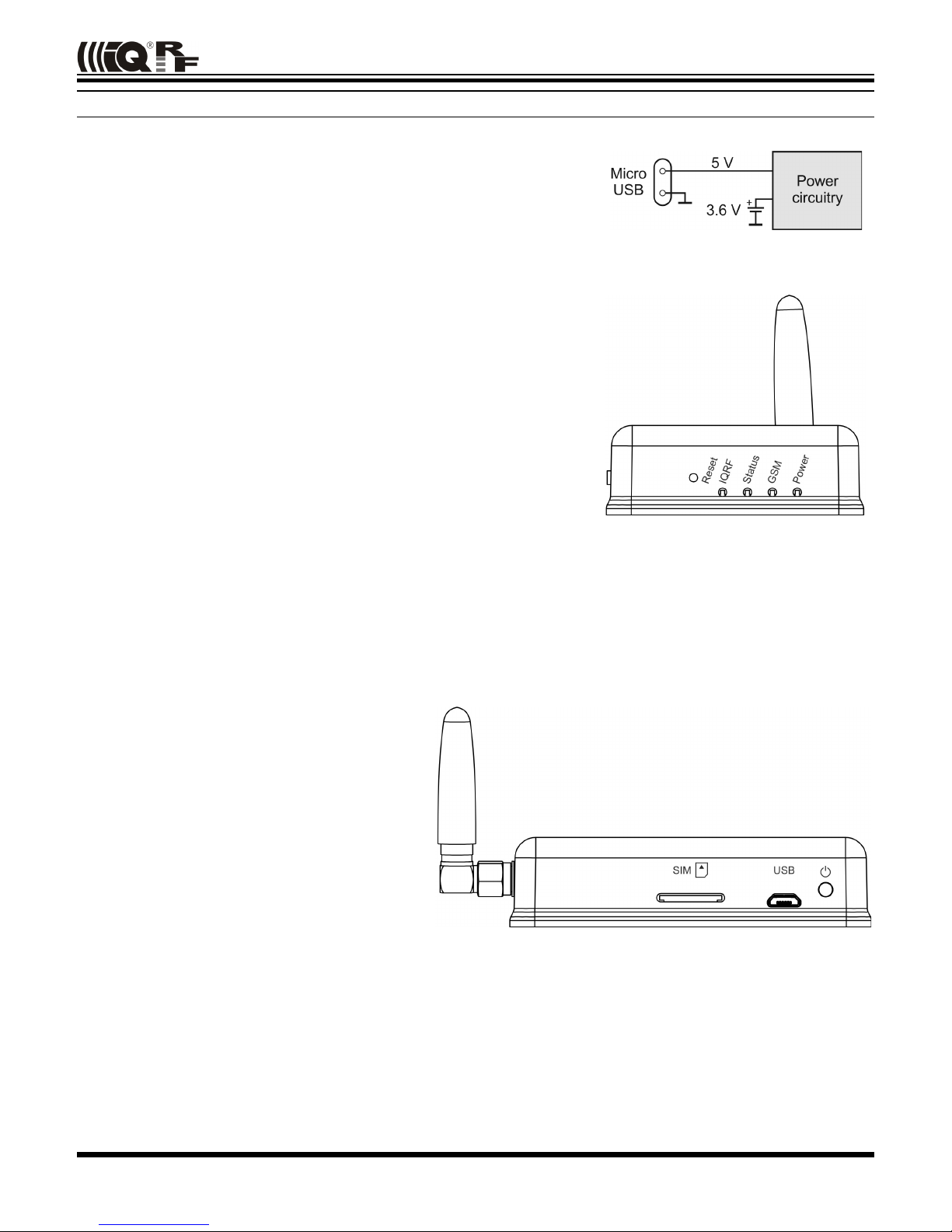
Power supply
GW-GSM-02 is intended to be supplied by external stabilized 5 V DC
connected to micro USB connector.
Accumulator
Backup accumulator is intended especially for short failures of external power
supply. It is not removable and enables continuous charging when external power is connected.
Power control button (ON / OFF)
• Short press (< 3s): no effect
• Long press (> 3s): Switching between operational and sleep modes
LED indication
Power LED (red)
Power LED is on when main power is on.
GSM LED (yellow)
• Flashes once per second when GSM module is powered.
• Flashing twice per second when communicating via GSM/GPRS.
Status LED (green)
• Status LED is on when GSM module is establishing connection to network.
• Flashing once per two seconds when GSM is logged in the network.
• Flashing two times per second when an error occurred (missing SIM card etc.)
IQRF LED (red)
This LED is controlled by the TR module, the LEDG output. Functionality is fully under control of user application program.
IQRF OS functions dedicated to LEDG can be used. In Demo SW this LED shortly flashes whenever an RF packet is
transmitted or received by TR module.
MCU
Microcontroller PIC18F26J50 by Microchip is used.
GSM
M590E dual band wireless module by Neoway is
used for GSM/GRPS connectivity.
SIM card
SIM card with activated data services from mobile
network operator must be plugged in the SIM
connector under the cover. Public IP address is
required (see below).
IQRF
TR-54DA wireless transceiver module is used for IQRF connectivity. Antenna is built in TR module.
Flash memory
SST25VF080B 1 MB Flash memory by Microchip/SST is used for gateway configuration and message buffer. Up to
100 000 erase/write cycles (typical) is allowed.
© 2013 MICRORISC s.r.o. www.iqrf.org UG_GW-GSM-02_131016 Page 4
Page 5

GW-GSM-02
Operation
GW-GSM-02 can completely be configured by the GW-GSM Tool PC software which is also intended for testing and
debugging. See the screenshots below.
It is necessary to obtain fixed public IP address from mobile network operator. GW replies to TCP packets sent to port
10001. The GW-GSM-02 can handle only one connection at the same time. Each connection is terminated 5 seconds after
sending data.
Date and time
GW-GSM-02 contains a real time clock / calendar (RTCC). Date and time must be set after every GW reset. Current time is
necessary for proper logging only.
Use SMS Alarm
This feature allows to send a short message to selected telephone number if an alarm is activated. Alarm activation is
initiated by the high logic level (log.1) pulse with minimum length 50 ms on pin C1 of TR module (MCU pin PORTA.0). After
alarm activation the gateway sends data prepared in bufferCOM in TR module. Alarm activation may precede sending data
itself. The data is sent only after the TR module executes the startSPI(n) command.
Access restriction
It is possible to enable IP address filtering. If enabled, only addresses specified in the address list are allowed for
communication with the server. The gateway supports up to 15 addresses in the list.
TR module data exchange
Data transmission from TR module to MCU in gateway is performed by command startSPI(n), where n is the length of
SPI data in bufferCOM in TR module. The maximum length of the SPI packet is 64 bytes. TR module receives data from
the main MCU to variable bufferCOM.
TR module powering
If the main MCU communicates with serial Flash memory, the TR module is switched off. This may occur also when
communicating with PC or during GSM transmission or reception. Thus, it is strongly recommended to provide TR modules
with a communication protocol ensuring proper communication in IQRF network (requesting to resend an answer to
incoming data not beeing served due to temporarily disabled TR module in GW-GSM-02).
© 2013 MICRORISC s.r.o. www.iqrf.org UG_GW-GSM-02_131016 Page 5
Page 6

GW-GSM-02
Data logging
GW-GSM-02 automatically stores data packets received from TR in internal Flash memory. Up to 3200 records can be
saved. The memory is organized as circular FIFO buffer. When the buffer is full, the sector (for 32 records) with the latest
messages is cleared and new records start to be saved there.
Data records format
#number#DDMMYYHHmmSS#data#
• number - record serial number
• DD – days
• MM – months
• YY – years
• HH - hours
• mm – minutes
• SS – seconds
• data - record payload data, length up to 64 B
• # - separator
System logging
GW-GSM-02 automatically logs system status and events. These messages are stored in Flash with the same format as
data records.
System records format
#number#DDMMYYHHmmSS#data#
• number - record serial number
• DD – days
• MM – months
• YY – years
• HH – hours
• mm – minutes
• SS – seconds
• data - event data and status
• # - separator
Event data and status
Each system record payload has the same length 8 B.
0 1 2 3 4 5 6 7
Event System agent GSM RSSI External Power Accumulator voltage
Event Type of event, see below
System Agent Additional information for start up and shutdown events, see below
GSM RSSI GSM Received Signal Strength Indication value in ASCII format (from 0 to 99)
Ext. Power 0x30 - External power not available, 0x31 - External power applied
Accumulator Voltage Value from A/D converter in hex format (AD = 000 to 3FF)
To calculate voltage, use this formula V
bat
= (AD + 671.03) / 327.71 V.
Example for AD = 190:
190 in hexadecimal = 400 in decimal, V
bat
= (400 + 671.03) / 327.71 V = 3.27 V.
Event byte System agent byte
Code ASCII Event Code ASCII Agent
0x30 0 Reset 0x30 0 Not defined
0x31 1 Power On (wake up) 0x31 1 Accumulator - GW switched to sleep because of low accumulator voltage
0x32 2 GSM login correct 0x32 2 USB - GW has been switched to sleep using software from PC
0x33 3 Power Off (sleep) 0x33 3 Button - GW has been switched to sleep using power button
0x34 4 GSM login failed
0x35 5 Server login failed
0x36 6 Send SMS failed
© 2013 MICRORISC s.r.o. www.iqrf.org UG_GW-GSM-02_131016 Page 6
Page 7

GW-GSM-02
Application
Firmware upgrade
MCU firmware is fixed but can be upgraded by the user with a new version released by the IQRF manufacturer via USB
and IQRF UDU software.
TR module application
GW-GSM-02 is delivered with the TR-GW-GSM-Demo application SW uploaded in TR module. It implements basic
operations and can be used as a template for user specific applications.
The Demo functionality is as follows:
TR module inside the GSM gateway continually attempts to receive IQRF packets possibly incoming from (an)other IQRF
device(s). If a packet containing temperature is recognized, it is checked whether the temperature exceeds the predefined
limit. If so, TR module generates an alarm signal via dedicated pin to main MCU and the gateway generates the alert SMS.
All incomming IQRF packets can be accesed remotely by TCP client or localy using USB connectivity. Both can be done
using GW-GSM Tool software.
Format of the packet containing the temperature is:"T:xx", where xx is the temperature in degrees, all 4 bytes in ASCII
characters. E.g. "T:35" means temperature 35 °C. The shape of the alarm signal is log. high for 50 ms on the PORTA.0
pin.
Remote temperature sensor can be simulated by another TR module connected to PC e.g. by CK-USB-04 development kit
or GW-USB-05 gateway connected to PC. Then packets can easily be created by IQRF IDE development environment
using built-in SPI Terminal.
The demo also enables to send IQRF packets. Any data recieved by TCP client is transmited by GW into the IQRF
nerwork. The TCP client uses an aplication protocol, described below.
The demo SW can be downoaded from the GW-GSM-02 product web page.
Application code can be developed and uploaded inside the GW-GSM-02 using the IQRF IDE 4 development environment.
© 2013 MICRORISC s.r.o. www.iqrf.org UG_GW-GSM-02_131016 Page 7
Page 8

GW-GSM-02
Application protocol
The communication is realized with the application protocol described below. It uses the transport protocol TCP according
the OSI reference model.
Connection establishment
To connect to the gateway operating in the Server mode, it is necessary to know the IP address of the gateway. IP can be
obtain from the GSM provider or it can be read using the GW-GSM Tool. The default port is set to 10001.
Commands
The GW-GSM-02 listens to commands from allowed IPs. The complete set of supported commands is listed in the
following table.
Command string Gateway action
record = ffff Returns last record
record = number Returns record with index number
dump Returns all records
dump_index = number Returns all records starting from index number
send_data = data Sends data to TR module
syslog Returns all system records
Number is formatted as four digit HEX value with lower case letters. Data is strictly in binary format.
Responses
Standard response to record data request (e.g., “record = 002f”) may be “#002f#060512031245#data#” according to
data and system record format described on the Data logging page. In some cases, the gateway replies error codes or
statements. The complete set of reply codes is listed in the following table.
Reply code Interpretation
FF0000000001
Invalid command
FF0000000002
Record not found
FF0000000003
Empty buffer
FF0000000005
Registration not successful
FF0000000006
No data to send
FF0000000007
Data successfully sent
Connection termination
TCP connection is terminated after 5 seconds of last TCP data packet sent.
© 2013 MICRORISC s.r.o. www.iqrf.org UG_GW-GSM-02_131016 Page 8
Page 9

GW-GSM-02
GW-GSM Tool
GW-GSM Tool is a PC program for setup, operation, testing and debugging of the GSM part of the gateway. It is free to
download from www.iqrf.or g/321 .
First steps
• Press the power button for at least 3 seconds to wake up the GW (if in sleep mode).
• Connect the gateway to PC using a USB cable.
• Install USB driver – Custom Class. You can download it from www.iqrf.org/89. This driver is the same also for other
IQRF USB devices. See the IQRF Quick start guide www.iqrf.org/235. If the IQRF IDE or another software using the
same USB driver (e.g. IQRF UDU) is installed, this step can be omitted.
• Run the GW-GSM Tool.
Caution: No other program communicating with any IQRF device via USB (e.g. IQRF IDE or IQRF UDU) is allowed to
run at the same time.
Basic setup
Settings – The tab to configure basic
gateway functions.
• APN – Access Point Name obtained
from the GSM network operator.
• PIN - if the SIM card is protected,
insert the PIN code and press
Update button
• Time – Time in HH.MM.SS format.
• Date – Date in DD.MM.YYYY format.
• Set Time button – sets a new time
to the RTCC. Other settings stay
unchanged. Once the button is
pressed, the time and date are
enabled for editing. Another press
of the button will launch the RTCC
with updatded values.
Use SMS Alarm – If the box is checked
the Send SMS function is enabled.
Telephone number must be specified in
the box below.
Use IP filtering – If the box is checked the access restriction function is enabled. Only IP addresses listed in Safe IPs list
can communicate with the gateway.
Safe IPs – To add a new address to the list, enter the address in the box below the list and press the Add button. To
remove an address from the list, select it and press the Rem button.
Update button - Updates the configuration of the GW-GSM-02.
© 2013 MICRORISC s.r.o. www.iqrf.org UG_GW-GSM-02_131016 Page 9
The Settings tab
Page 10

GW-GSM-02
Data logging
Logs – the tab to read system or data
records and clear all log memory.
Read button – loads the entire
contents of the internal memory to the
list above.
Clear Memory button – deletes all
logs stored in Flash memory
Log type selection
IQRF – To display data records logged
from TR module only.
System – To display records with
logged system states and events only.
Log display selection
ASCII tab - All recorded bytes are
interpreted and displayed as ASCII
characters.
HEX tab - All recorded bytes are
displayed in hexadecimal format. Each byte is separated by the dot character.
TCP Client
TCP client tab to test the gateway.
IP address of the gateway must be
filled in the box above the Connect
button. When the GW-GSM Tool is
connected to the gateway via USB
cable, the IP address is stated
automatically.
Port number – fixed 10001 value is
used.
Connect button establishes a TCP
connection to the gateway.
Send button – Sends packet to the
gateway containing data from the box
above the Send button. This control
works only when the client is connected
to a TCP server.
Data box - This box contains
predefined commands for TCP server.
Any additional data can be entered into
the box.
Clear window button - clears the TCP
client terminal window.
© 2013 MICRORISC s.r.o. www.iqrf.org UG_GW-GSM-02_131016 Page 10
Predefined commands
TCP client tab
Logs tab - hex format
Page 11

GW-GSM-02
Info window
This window shows the simplified
information from the gateway.
• Device - Gateway product code
• Version - Gateway firmware version
• ID - Unique gateway identification
number
• GSM RSSI - Receive Signal
Strength Indicator of GSM network
• Accu Capacity - Estimated backup
battery life
• Accu Voltage - Actual battery
voltage
Command window
• GW status - Current command
executing by GSM module
• GW IP - Gateway IP address
• Client IP - IP address of connected
client
• Toggle LED - Toggles gateway
status LED
• Reset GSM - Reset GSM module in
the gateway
• GW Sleep - Switches gateway into
the sleep mode
© 2013 MICRORISC s.r.o. www.iqrf.org UG_GW-GSM-02_131016 Page 11
Info window
Command window
Page 12

GW-GSM-02
Product information
Pack list
• GW-GSM-02 IQRF GSM gateway, with the accumulator and GSM SMA antenna
• TR-54DA IQRF TR module (with built-in antenna) inside, demo SW uploaded
• TY-A6 Power supply (Input: 100 V – 240 V AC, EU plug. Output: 5 V DC, 500 mA, USB A
connector, cordless.)
• CAB-USBABMICRO Power supply cord (for TY-A6) with microUSB output connector
Ordering codes
• GW-GSM-02 IQRF GSM gateway
Requested option
• SIM card with activated data services from mobile network operator
Firmware history
• v1.00 First release
Document history
• 131016 First release
© 2013 MICRORISC s.r.o. www.iqrf.org UG_GW-GSM-02_131016 Page 12
Page 13

GW-GSM-02
Sales and Service
Corporate office
MICRORISC s.r.o., Prumyslova 1275, 506 01 Jicin, Czech Republic, EU
Tel: +420 493 538 125, Fax: +420 493 538 126, www.microrisc.com
Partners and distribution
Please visit www.iqrf.org/partners
Quality management
ISO 9001 : 2009 certified
Complies with Directive 2002/95/EC (RoHS)
Trademarks
The IQRF name and logo and MICRORISC name are registered trademarks of MICRORISC s.r.o.
PIC, SPI, Microchip and all other trademarks mentioned herein are property of their respective owners.
Legal
All information contained in this publication is intended through suggestion only and may be superseded by updates
without prior notice. No representation or warranty is given and no liability is assumed by MICRORISC s.r.o. with respect to
the accuracy or use of such information.
Without written permission it is not allowed to copy or reproduce this information, even partially.
No licenses are conveyed, implicitly or otherwise, under any intellectual property rights.
The IQRF ® products utilize several patents (CZ, EU, US)
On-line support: support@iqrf.org
© 2013 MICRORISC s.r.o. www.iqrf.org UG_GW-GSM-02_131016 Page 13
 Loading...