

Page 1

GW-ETH-02A
IQRF Ethernet Gateway
Firmware v2.80
User's Guide
© 2016 MICRORISC s.r.o. www.iqrf.org User_Guide_GW-ETH-02A_160208 Page 1
Page 2
GW-ETH-02A
© 2016 MICRORISC s.r.o. www.iqrf.org User_Guide_GW-ETH-02A_ 160208 Page 2
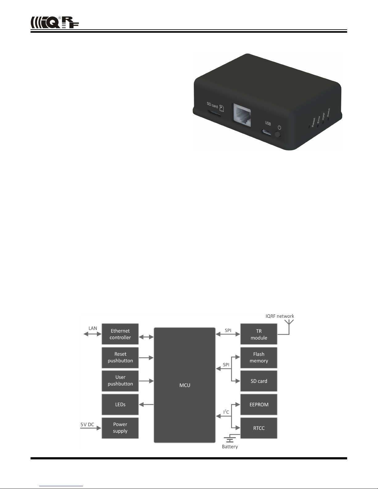
Description
GW-ETH-02A is an IQRF gateway for connection between IQRF
and Ethernet networks allowing remote monitoring, data collection
and control of IQRF network.
Main components are: 32b microcontroller, Ethernet controller,
EEPROM memory, serial Flash memory, SD memory card, IQRF
transceiver module with antenna and RTCC.
The gateway can communicate outside the IQRF network via
Ethernet. Configuration is possible via internal www server, IQRF
IDE or SD card.
GW-ETH-02A allows communication with IQRF IDE to configure
internal TR module and simply create IQRF networks. It is fully
compatible with the DPA protocol. Non-DPA applications are
supported as well.
GW-ETH-02A supports exchanging data with any cloud server
designed according to IQRF Cloud server specification.
Applications
• Remote monitoring and control
• Data acquisition / collection
• Datalogger, IQRF Cloud supported
• Interface to building / home automation
• Connection of more IQRF networks to single PC
• DPA as well as non-DPA applications supported
Key features
• HTTP client for communication with IQRF Cloud server
• HTTP server for remote management
• UDP server/client for communication with IQRF network
• DDNS support
• SNTP client for getting date and time from Internet
• DHCP client for automated getting of IP address
• NBNS server for using names instead of IP addresses
• RTCC (real time clock/calendar)
• Firmware upgrade via web server / SD card
• Upgrade of application in internal TR module via web
server / IQRF IDE / SD card
• DPA and IQRF IDE compatible
Block diagram
Page 3

GW-ETH-02A
This gateway can be used either with TR as well as with DCTR transceivers. For simplicity, only TR is mainly used further
on throughout this document.
Electrical specifications (Typical values unless otherwise stated)
Power supply 5.0 ± 0.35 V DC
RTCC backup battery CR2032 3 V, 215 mAh
Supply current
Off
USB cable disconnected 1 µA
USB cable connected 4 mA
Operating
TR and Ethernet inactive 150 mA
Additional current
TR active See datasheet of TR module
Ethernet active 50 mA
Temperature range
Operating 0 °C to +60 °C
Storage 10 °C to +20 °C (recommended)
IQRF
Frequency bands 868 MHz or 916 MHz (SW selectable)
RF output power According to TR module, programmable
TR module DCTR-52DA
Antenna PCB antenna built-in TR module
Flash memory SST25VF080B, 8 Mb, 100 000 erase/write cycles typ.
SD card Up to 2 GB
Ethernet 100BASE-TX
USB Custom class
Dimensions 87 mm x 62 mm x 26 mm
Weight 70 g
Absolute maximum ratings
Stresses above those values may cause permanent damage to the device. Exposure to maximum rating conditions
for extended periods may affect device reliability.
Supply voltage (VCC) 5.5 V
Storage temperature -20 °C to +60 °C
© 2016 MICRORISC s.r.o. www.iqrf.org User_Guide_GW-ETH-02A_ 160208 Page 3
Page 4
GW-ETH-02A
Hardware
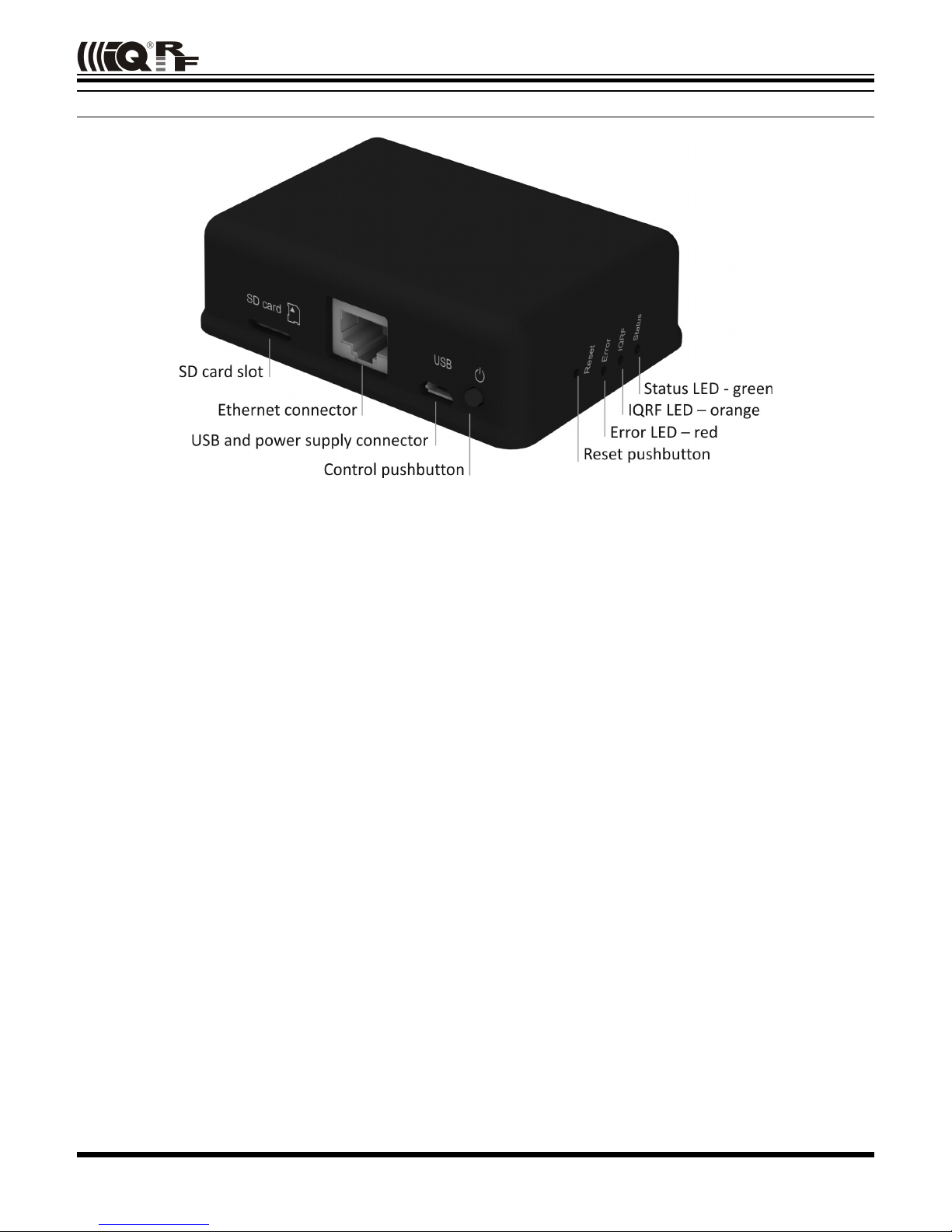
Power supply
GW-ETH-02A should be supplied via standard micro USB connector by external stabilized 5 V DC, e.g. from the
power source delivered with the GW or from USB interface.
Ethernet
Ethernet/LAN line should be connected via standard 8-pin RJ-45 connector.
Pushbuttons
Both Reset and Control pushbutton functionality is fixed and can not be changed in application program.
Control
• Short press (< 1 s): no effect
• Long press (>1 s, < 10 s): GW off
• Long press (> 10 s): restore the factory settings of the gateway. (After 10 s all LEDs get off to indicate that the factory
setting was restored.)
Reset
Reset button can be pressed by a pin through the hole in the case. It is intended to reset the gateway (equally to
switching the GW power supply off and on). Current GW configuration stays unchanged. For reinitializing the GW (to
restore the factory settings), use menu Maintenance → Factory Defaults at Web server.
LEDs
See Appendix 1 – LED indication.
IQRF
DCTR-52DA or DCTR-72DA wireless transceiver module is used for IQRF connectivity. Antenna is built in DCTR module.
© 2016 MICRORISC s.r.o. www.iqrf.org User_Guide_GW-ETH-02A_ 160208 Page 4
Page 5

GW-ETH-02A
Flash memory
Log data is stored in circular buffer in Flash memory. When it is full and a subsequent write is performed, then it
starts overwriting the oldest data.
There is 252 KB dedicated to IQRF RX data and 128 KB for IQRF TX data and same size for System log.
The number of records of IQRF RX/TX data depends on the parameter Packet size, which define how many
payload data bytes is dedicated for every data record. For default setting ( Packet size = 64 B) there is 3308
positions for IQRF RX and 1680 positions for IQRF TX. For System log there is always 6553 positions in the buffer.
The actual size of the data log is the Packet size + 14 B, where the additional 14 bytes are used for saving date,
time and index of the log. In this way the user can calculate actual number of positions in the buffer.
Data volumes and recording frequency must be taken in account with respect to the Flash memory endurance.
When the Packet size is changed in the GW settings, all logs are cleared.
Case
Caution: It is not allowed to open the GW case otherwise the device may be damaged.
© 2016 MICRORISC s.r.o. www.iqrf.org User_Guide_GW-ETH-02A_ 160208 Page 5
Page 6
GW-ETH-02A
Operation
Start up
GW-ETH-02A is turned on by USB power supply connecting.
Initialization
• After the start-up, the GW checks its own hardware first. If there is no critical error it starts to initialize Ethernet.
When a critical error occurs, the execution does not continue and the error code is indicated by LEDs.
Communication
The size of payload IQRF data transmitted between the GW and the IQRF network is limited to 64 B in both
directions.
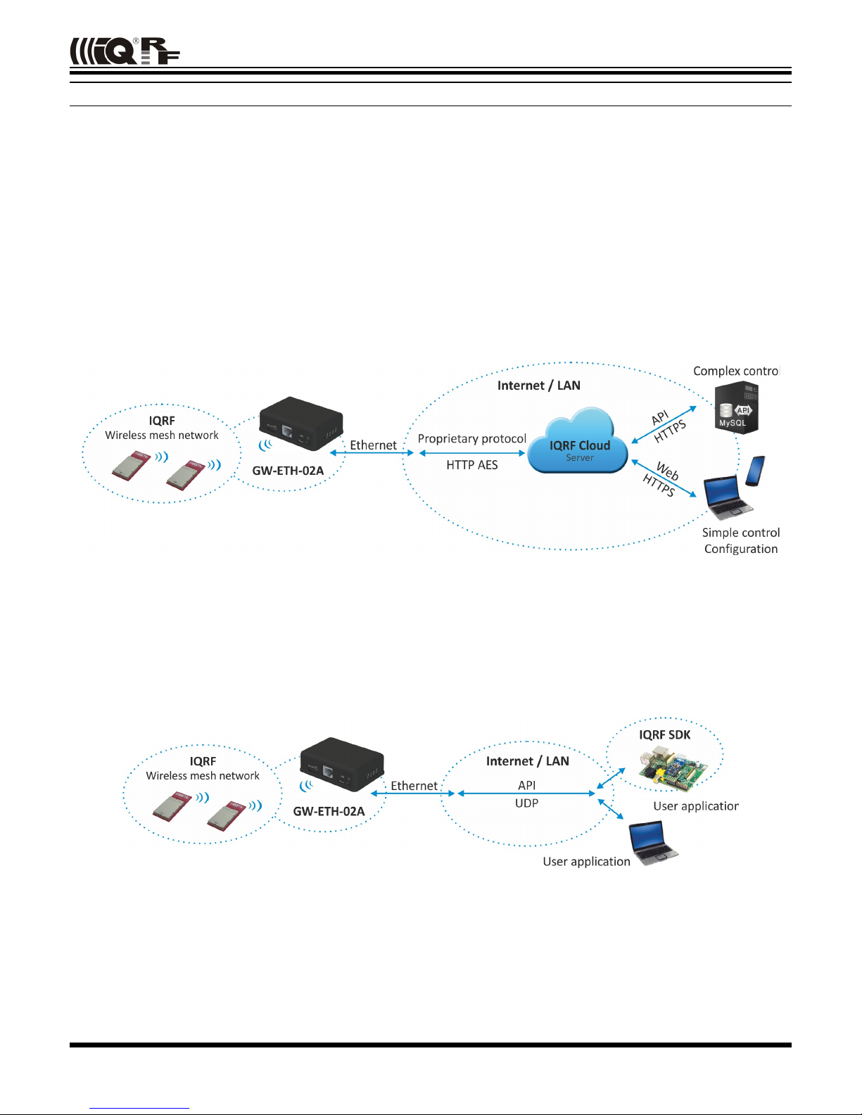
GW-ETH-02A can work in the following modes:
Datalogger mode
• All incomming IQRF data (IQRF RX) is stored and logged in internal Flash memory. When used with IQRF Cloud,
the logged data is transmitted to the Cloud server always after the Cloud period elapsed. See chapters IQRF IDE –
GW Tool and Web server.
• Data to be sent to IQRF (IQRF TX) is stored in internal Flash memory. When used with IQRF Cloud, the data is
stored in the Cloud server first, transferred to the GW always after the Cloud period elapsed and then forwarded to
IQRF network.
• If the communication between the GW and the Cloud server failed, the GW indicates an error.
Gateway mode
• Direct connection between IQRF networks and remote device via UDP channel is established.
• The communication uses a specific application protocol, see chapter Application protocol for UDP channel.
• Errors in communication between the GW and the remote device should be solved by the user application.
© 2016 MICRORISC s.r.o. www.iqrf.org User_Guide_GW-ETH-02A_ 160208 Page 6
Page 7
GW-ETH-02A
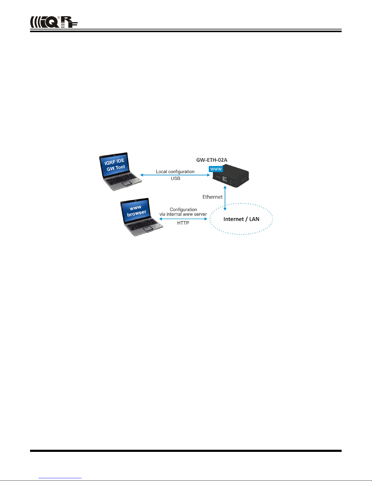
Using IQRF IDE
• The IQRF IDE GW Tool is intended for GW configuration, checking of operational and error states and for access to the
datalogger. When using the GW Tool, the communication via Ethernet is enabled.
• Additionally, IQRF IDE can be used similarly as for the CK-USB-04(A): uploading the code into TR transceiver,
configuration of TR module inside the GW, debugging of the application, using the IQMESH Network manager etc.
In this mode the communication via Ethernet is disabled.
Internal web server
To get connected to the internal web server it is necessary to know IP address of the GW or the GW host name (if
the network supports the NBNS, i.e. within the LAN only). Internal web server is used for GW configuration (manually
in graphic environment or by loading a binary file *.gwcnfg), datalogger reading (TX, RX, System log), TR module
programming (*.hex, *.iqrf, *.trcnfg) and FW upgrading (gweth.hex). When uploading any of these files, it is
necessary to have SD card plugged in the GW card slot, otherwise the operation can not be completed.
GW configuration
GW configuration is possible via internal www server, IQRF IDE or (especially for troubleshooting) via SD card.
© 2016 MICRORISC s.r.o. www.iqrf.org User_Guide_GW-ETH-02A_ 160208 Page 7
Page 8

GW-ETH-02A
SD card file structure
The SD card is intended for development, service and maintenance. It should be accessed primarily by the GW while
direct writing by the user (externally by a standard SD card reader/writer) is recommended for exceptional purposes
only. The standard way to perform required changes is using the internal web server.
The SD card uses the following folders:
• Root The root directory is intended for a new FW (gweth.hex file) to be used for upgrade.
• TRUPLOAD The folder intended for files to be uploaded into the TR module (*.hex, *.iqrf, *.trcnfg).
• GWCNFG The folder intended to record a new GW configuration (*.gwcnfg).
• BACKUP The folder intended for current GW configuration (gw.gwcnfg).
When using the web server, all folders and files are created automatically when required. In case of external direct
writing the required folders must be created by the user. Files not necessary any more are automatically deleted after
the usage.
System log
All important events are logged. System logs can be read using IQRF IDE GW Tool or the GW web interface.
Date and time
GW-ETH-02A contains a real time clock/calendar (RTCC). Date and time are synchronized using SNTP/Cloud
server.
TR module data exchange
Data between the internal TR module and the GW memory is transferred bidirectionally via SPI (using the
bufferCOM memory array inside the TR module). Therefore, the application in TR must have the SPI communication
activated. When using DPA, a hardware profile with SPI interface must be uploaded in TR. Such plug-in is
uploaded from the factory. The maximum SPI packet length is 64 B.
Ethernet services
• HTTP client for communication with IQRF Cloud server (using the 128 b AES encryption)
• HTTP server offering web pages for remote management via a common browser
• HTTP client for getting and updating of public address from DDNS
• UDP server/client for communication with IQRF network and for remote GW management
• SNTP client for getting date and time from time server
• ICMP server allowing “ping” to GW from a remote host
• DHCP client for automated getting of IP address from the DHCP server
• NBNS server for using names instead of IP addresses within the LAN
GW identification
MAC address
Every device has a unique MAC address in the format 00 1F D5 xx xx xx, where:
• 00 1F D5 is the OUI dedicated to MICRORISC s.r.o.
• xx xx xx is a device serial number
Actual MAC address is printed on the label at the bottom of the GW-ETH-02A case.
ID
Another unique number (manufacturer's identification) used to identify the gateway by IQRF IDE, the IQRF Cloud server
and user applications utilizing the Cloud via API.
For GW-ETH-02A: ID = 12 xx xx xx, where xx xx xx are last 6 digits of the MAC address.
NBNS Name
iqrf_xxxx, where xxxx are the last 4 digits of the MAC address.
© 2016 MICRORISC s.r.o. www.iqrf.org User_Guide_GW-ETH-02A_ 160208 Page 8
Page 9
GW-ETH-02A
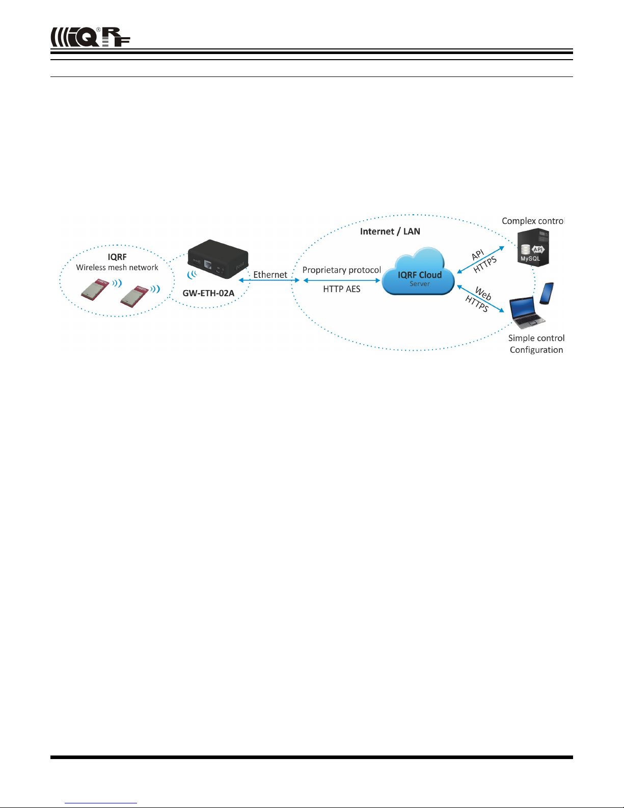
IQRF Cloud
The IQRF Cloud provides an effective way to exchange data between IQRF wireless device(s) and a user
superordinary system implemented by a higher level platform (e.g. PHP, JavaScript or web interface) and connected
via Internet or a LAN.
As an interface to IQRF, the GW-ETH-02A or another IQRF gateway providing Internet connectivity (Ethernet, GPRS
or WiFi) is intended.
An IQRF Cloud server is available free of charge on http(s)://cloud.iqrf.org provided by CIS (Complete
Internet Services, s.r.o., an IQRF contractual partner for cloud solutions). Moreover, a licensed version is available for
every user of an IQRF gateway prefering to implement and operate one's own IQRF Cloud. Refer to the IQRF Cloud
User's Guide for details.
© 2016 MICRORISC s.r.o. www.iqrf.org User_Guide_GW-ETH-02A_ 160208 Page 9
Page 10
GW-ETH-02A
IQRF IDE – GW Tool
IQRF IDE 4.20 and higher is required.
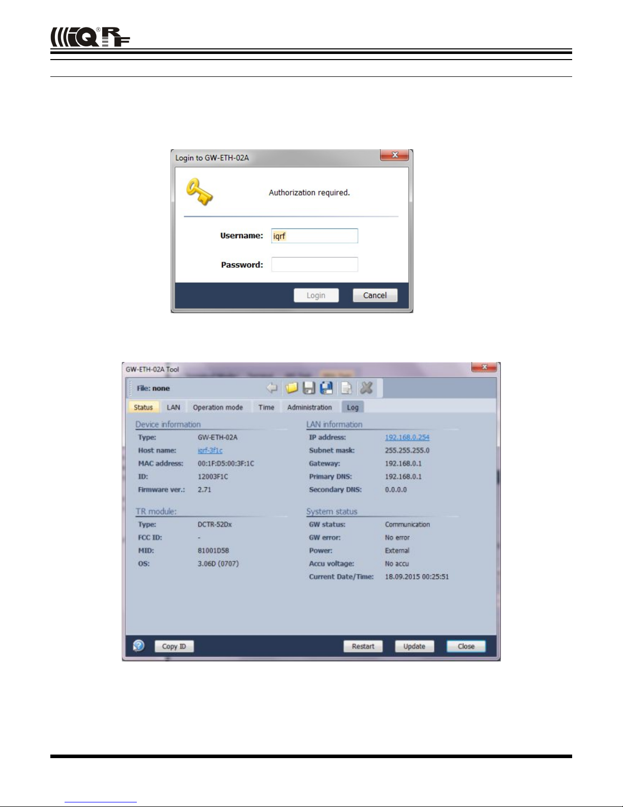
Login to GW Tool
The GW Tool can be invoked from IQRF IDE menu Tools → GW Tool.
To open the Tool, the username and the password must be entered. Default values are iqrf and iqrf.
Status
The Status tab contains general overview about the gateway status. Several buttons are available to control the GW:
• Copy ID To copy the GW ID to the clipboard
• Restart To restart the gateway
• Update To update the Status tab
• Close To close the GW Tool window
© 2016 MICRORISC s.r.o. www.iqrf.org User_Guide_GW-ETH-02A_ 160208 Page 10
Page 11

GW-ETH-02A
Device information
• Type Current GW type
• Host name Name identification of GW in Ethernet network (used by NBNS)
• MAC address Globally unique identification of GW – Ethernet interface
• ID Unique identification number of the gateway
• Firmware ver. Current firmware version
TR module
• Type IQRF TR module type inside the gateway
• FCC ID FCC certification identification
• MID Unique IQRF TR module identification number
• OS IQRF OS version of the TR module
LAN information
• IP address Current IP address of the GW
• Subnet mask Ethernet network address range
• Gateway Main gateway/server of the Ethernet network
• Primary DNS Primary server with DNS service
• Secondary DNS Secondary server with DNS service
System status
• GW status Current operation executed by the gateway:
• Communication
• Cloud Server Communication
• Error
• GW error An error during execution indication:
• No Error
• TR SPI Error
• LAN Error
• Cloud Server Error
• SD Card Error
• Power „External“ – irrelevant for GW-ETH-02A
• Accu voltage „No accu“ – irrelevant for GW-ETH-02A
• Current Date/Time The date and time used in the gateway
© 2016 MICRORISC s.r.o. www.iqrf.org User_Guide_GW-ETH-02A_ 160208 Page 11
Page 12
GW-ETH-02A
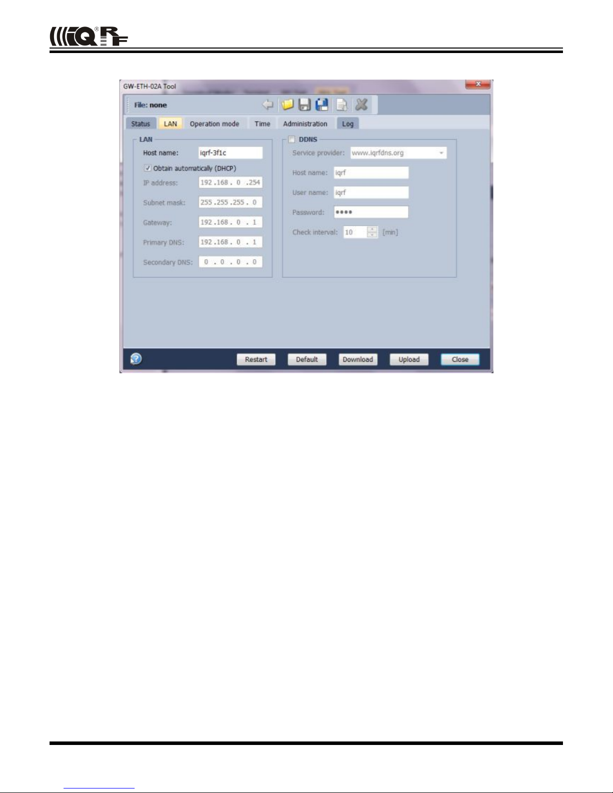
LAN
The following buttons are available in addition to previous ones:
• Restart To restart the GW with current configuration
• Default To restore the default configuration
• Download To read the configuration from GW
• Upload To store the configuration to GW
LAN
It allows to set/get the parameters relating to Ethernet connection.
• Host name Name identification of GW in the Ethernet network (used by NBNS). If the main gateway/server
offers NBNS service, it is allowed to use this host name instead IP address of GW
• Obtain automatically (DHCP) If the main gateway/server offers DHCP service, it is allowed to get all LAN
parametres automatically (IP address, Subnet mask, Gateway, Primary DNS,
Secondary DNS)
• IP address Current IP of the GW
• Subnet mask Ethernet network address range
• Gateway Main gateway/server of the Ethernet network
• Primary DNS Primary server with DNS service
• Secondary DNS Secondary server with DNS service
© 2016 MICRORISC s.r.o. www.iqrf.org User_Guide_GW-ETH-02A_ 160208 Page 12
Page 13

GW-ETH-02A
DDNS
DDNS service allows to get public address of network which the GW is assigned in. GW communicates with the
DDNS server in checking interval and transmits its current IP address.
• For IQRF DNS:
The user or user application reads the IP address from the service provider server using the ID of the GW.
• For other DDNS servers:
The user or user application accesses the GW using the Host Name. Refer to the website of given server.
• DDNS DDNS service activation
• Service provider List of supported DDNS servers
• Host name Name identification of GW within DDNS
• User name DDNS account username
• Password DDNS account password
• Check Interval Communication period between the GW and DDNS server
© 2016 MICRORISC s.r.o. www.iqrf.org User_Guide_GW-ETH-02A_ 160208 Page 13
Page 14

GW-ETH-02A
Operation Mode
The Operation mode tab provides the setting of the gateway.
Mode
• Dataloger The datalogger is active. Its content can be read using IQRF Cloud server (if enabled), GW web
server or IQRF IDE GW Tool.
• Gateway UDP channel is active. It is direct connection to the GW (without IQRF Cloud) using the
application protocol described in chapter Application protocol.
Communication ports can be selected in the Gateway field - Port and Remote port.
Logger
• Packet Size The size dedicated for the data log in the gateway memory. By default, this value is set to 64 B,
the same as the maximum size of the IQRF packet. Shorter packets allow to store more data
logs. Minimum packet size is 1 B. When an IQRF packet oversizes the selected packet size, a
part of user data is lost.
When the packet size is changed the content of internal memory is cleared.
IQRF Cloud
• Period Defines how often the gateway transmits the data to IQRF Cloud server. Allowed values are from
2 s to 24 hours.
• Use IQRF Cloud hosted by CIS The gateway is configured by default to communicate with IQRF Cloud server
provided by CIS. Any gateway can also communicate with another IQRF Cloud server provided
by anyone else. In such a case, the checkbox must be unchecked and the following fields must
be filled.
• AES key Encryption key used for secure communication between the gateway and the IQRF Cloud server.
The same key must also be specified at the server side.
• Cloud path The URL address where IQRF Cloud server is hosted. The '/cloud' substring must follow
• Cloud port The TCP port used. In most cases port 80 is used.
Gateway
• GW Port UDP port for the GW side.
• Remote port UDP port for a remote device side.
© 2016 MICRORISC s.r.o. www.iqrf.org User_Guide_GW-ETH-02A_ 160208 Page 14
Page 15

GW-ETH-02A
Time
GW time and date setup.
Set time
• Manual To setup the time manually
• PC time To upload the date and time from connected PC.
Selected time is transferred to the GW by the Set Time button.
GW time
• Current GW Date/Time Date and time currently running in the GW
• Time zone Time zone selection
• Use daylight savings Daylight savings for given time zone selection
• Use SNTP server When activated, the GW time will be synchronized with speicified SNTP server time once
per 6 hours.
• Server SNTP server selection. IQRF Cloud server is also available for this.
© 2016 MICRORISC s.r.o. www.iqrf.org User_Guide_GW-ETH-02A_ 160208 Page 15
Page 16

GW-ETH-02A
Administration
The user can change the username and the gateway password here. When the password is changed, in order to
allow an access the data on the Cloud server it must be changed there too. The change of username has no effect
for that. Allowed password length is from 4 to 8 characters. When the username or the password is lost, the user can
reset the gateway to factory settings. The default username and password values are iqrf and iqrf.
HTTP Server
• Disable remote management Internal web server inside the GW can be disabled. The change takes effect
after GW reset. The configuration through IQRF IDE – GW Tool is possible
even if this option is disabled.
© 2016 MICRORISC s.r.o. www.iqrf.org User_Guide_GW-ETH-02A_ 160208 Page 16
Page 17

GW-ETH-02A
Log
Transmitted data stored on the Cloud server stays also accessible directly in the GW buffer.
Buttons:
• Restart To restart the GW
• Erase Log To erase the content of the whole GW internal log memory
• Update To read the data from the GW and refresh the Log window
• Close To close the GW Tool window
Three types of logs are stored in the gateway:
• IQRF Rx Data received from IQRF network and transmitted to the Cloud server
• IQRF Tx Data downloaded from Cloud server and transmitted to IQRF network
• System Certain events that occurs during the execution. The user do not usually need to take care about it.
Nevertheless it can be helpful in case of nonstandard behavior.
Last Record When selected, the output list is scrolled down to display the last acquired data.
The format of IQRF RX/TX data depends on the user application in TR (e.g. DPA or any user-specific protocol). The
format of system log is fixed. It contains the following information:
© 2016 MICRORISC s.r.o. www.iqrf.org User_Guide_GW-ETH-02A_ 160208 Page 17
Page 18

GW-ETH-02A
The following system events are logged:
• GW_ON_BY_EXT_POWER_ON
• GW_RESET_FOR_NEW_SETTINGS
• GW_LAN_ERROR
• SD_CARD_ERROR
• CLOUD_REGISTRATION_DONE
• CLOUD_LICENSE_DONE
• CLOUD_CONNECTION_ERROR
• CLOUD_REGISTRATION_ERROR
• CLOUD_UPLOAD_ERROR
• CLOUD_DOWNLOAD_ERROR
• CLOUD_DOWNLOAD_CONF_ERROR
• CLOUD_SYSTEM_PACKET_ERROR
• CLOUD_UNKNOWN_PACKET_RECEIVED
• CLOUD_LICENSE_ERROR
• TR_SPI_ERROR
© 2016 MICRORISC s.r.o. www.iqrf.org User_Guide_GW-ETH-02A_ 160208 Page 18
Page 19

GW-ETH-02A
Web server
The web server inside the GW is primarily intended for GW
configuration and for local reading out from the datalogger. To access
the web server, the IP address of given GW must be known. When
accessing from a local network, the domain name 'iqrf_xxxx'
(where xxxx are last 4 digits of the MAC address) can be used
instead of the IP address. Both GW user name and the GW password
are preset to 'iqrf' from the factory. Every page of the web server
has a help.
It is recommended to change the user name and it is required to
change the GW password as soon as possible, just after the first login
to the web server.
Web server can be enabled/disabled in IQRF IDE GW
Tool/Administration.
The web server implemented inside the GW-ETH-02A should be accessed by any common up-to-date web browser
except of Internet Explorer by Microsoft.
Menu
The main menu provides an access to the configuration pages of GW.
• Status page shows information about the device, current network
connection and the GW status.
• LAN Setup page allows to select the network connection parameters.
• Operation Mode page allows to select GW mode which GW works in.
• Dynamic DNS page allows to configure Dynamic DDNS service used to
find the public IP address of the GW.
• Password page allows to change the access parameters for the Web
server, Cloud server and IQRF IDE.
• Time page allows to set the time and date manually or to activate
automatic time synchronization with the selected time server.
• Maintenance is intended for fundamental changes in GW and internal TR
functionality.
© 2016 MICRORISC s.r.o. www.iqrf.org User_Guide_GW-ETH-02A_ 160208 Page 19
Page 20

GW-ETH-02A
Status
Device information
• Type GW type
• Host Name Name identification within local network (using this name instead of IP address), in the networks
where NBNS is supported
• MAC Address Globally unique identification of GW device within Ethernet networks
• ID Unique identification of the gateway within the MICRORISC product line
• Firmware Version Current firmware version (and build date)
LAN information
The network connection parameters set manually or obtained through DHCP.
TR module
• Type TR module type inside the GW
• MID Unique IQRF TR module identification number
• OS Current version of IQRF OS (and build version) of TR module
• Status: The state which the TR module is in
System status
• GW Status Current operation executed by the gateway. See chapter System status above.
• GW Error: Indicates whether there is an error during execution
• Power Power supply type
• Accu Voltage Not intended for GW-ETH-02A
• Current Date/Time Current time of RTCC inside the GW
© 2016 MICRORISC s.r.o. www.iqrf.org User_Guide_GW-ETH-02A_ 160208 Page 20
Page 21

GW-ETH-02A
LAN setup
On this page it is possible to change the name (Host Name) for access to the GW which can be used within a local
network instead of the IP address. If the DHCP service is available in the network, the Obtain automatically checkbox
should be activated, otherwise the parameters for access to the LAN network must be selected manually.
In the factory settings, these parameters are obtained automatically from the network using DHCP.
© 2016 MICRORISC s.r.o. www.iqrf.org User_Guide_GW-ETH-02A_ 160208 Page 21
Page 22

GW-ETH-02A
Operation mode
• Mode Datalogger Mode activates storing data from IQRF network. This data can be read at the Data
Interface page, by the Cloud server (if the communication with the Cloud server is enabled) or
using IQRF IDE.
Gateway mode enables communication via UDP channel between the GW and a remote system
according to the documented application protocol.
The default setting is Datalogger mode.
• Packet Size The size of the user data in IQRF packets. By selecting a smaller value is possible to store a
larger number of packets. If the actual IQRF packet is longer, the remaining data is not saved.
• IQRF Cloud Enabled Activates the communication with the Cloud server
• Period Communication period which GW uploads/downloads data to/from the Cloud server in. Every digit
of the double-figure number is set separately.
• Use IQRF Cloud hosted by CIS Allows to utilize the ready-to-use IQRF Cloud server hosted by CIS.
• AES key Encryption key used for the first connection to the Cloud server
• Cloud Path The URL address where IQRF Cloud server is hosted. The '/cloud' substring must follow
• Cloud Port The TCP port used. In most cases port 80 is used.
• GW Port UDP port for the GW side.
• Remote port UDP port for a remote device side.
• Save The button to confirm changes and close the window.
© 2016 MICRORISC s.r.o. www.iqrf.org User_Guide_GW-ETH-02A_ 160208 Page 22
Page 23

GW-ETH-02A
Dynamic DNS
• Active Dynamic DNS Activates the GW - DDNS server communication. In the factory settings the DDNS is
inactive.
• Service Provider DDNS service provider selection
• Host Name Name identification of the GW within DDNS
• User Name Username for DDNS account
• Password Password for DDNS account
• Check Interval Communication period between the GW and the Service provider server (in minutes).
Minimum value is 10 minutes.
Password
In factory settings the User Name and the Password are " iqrf". The password should be changed by the user on
the Password Setup page. To accomplish a change, the original password and the new one must be stated. For
security, the new password must be typed two times.
When the password is forgotten, the factory settings of the GW must be restored by the Control pushbutton (see
chapter Pushbuttons above). Then the factory preset username and password are restored.
© 2016 MICRORISC s.r.o. www.iqrf.org User_Guide_GW-ETH-02A_ 160208 Page 23
Page 24

GW-ETH-02A
Time
The Time Setup allows to set the time of the internal clock measured by the GW. The time is required especially for
the datalogger. Individual logs are provided with time stamps. The time can be setup manually or via the SNTP
service. The SNTP provides periodical time synchronization from one of selected time servers. As a time server, the
IQRF Cloud server can be used as well. In the factory settings the time and date are synchronized with the IQRF
Cloud server.
Maintenance
• Main Menu returns from the Maintenance page to main menu.
• Factory Defaults allows to restore the original factory settings or reboot the
gateway.
• Configuration page allows to write / read the GW configuration binary file
*.gwcnfg.
• TR upload page is used to program the TR module.
• FW upgrade page allows to upload a new firmware.
Factory Defaults
• Restore factory defaults + Reboot restores the GW settings to values preconfigured by the GW manufacturer and
reboots the GW.
• Reboot only reboots the GW (keeping the current GW configuration).
• Execute launches the operation selected above.
© 2016 MICRORISC s.r.o. www.iqrf.org User_Guide_GW-ETH-02A_ 160208 Page 24
Page 25

GW-ETH-02A
Configuration
This page allows to upload the binary configuration file *.gwcnfg or generate this file based on the current GW
settings. This type of file can be also generated by IQRF IDE GW Tool.
TR upload
This page allows to reprogram the TR module inside the GW. Supported files are *.hex, *.iqrf and *.trcnfg.
*.trcnfg can be generated by export of TR configuration in IQRF IDE.
FW Upgrade
This page allows to upgrade the GW by a new firmware (file gweth.hex) which may be released by IQRF
manufacturer and available on the product web page. See chapter FW upgrade – Bootloader below.
© 2016 MICRORISC s.r.o. www.iqrf.org User_Guide_GW-ETH-02A_ 160208 Page 25
Page 26

GW-ETH-02A
Factory setup
This initial setup can be restored whenever the control button is pressed for more than 10 s. This can be useful if it is not
possible to establish communication due to wrong configuration.
LAN ------------------------------------------------------------------------------------------------------------------------------------------------------
• NBNS name „iqrf_xxxx“, where xxxx are last 4 digits of the MAC address.
• Get IP address from DHCP server automaticallyon
• IP address 192.168.0.254
• Subnet mask 255.255.255.0
• Gateway 192.168.0.1
• Primary DNS server: 192.168.0.1
• Secondary DNS server 0.0.0.0
Operation Mode ---------------------------------------------------------------------------------------------------------------------------------------
• Mode Datalogger
• Packet Size 64B
• IQRF Cloud Communication Enabled
• Use IQRF Cloud Server hosted by CIS Enabled
• Communication period 10 s
• GW port for the application protocol 55300
• Host port for the application protocol 55000
Dynamic DDNS ---------------------------------------------------------------------------------------------------------------------------------------
• Dynamic DNS Disabled
Password ----------------------------------------------------------------------------------------------------------------------------------------------
• Authorization when enter the internal web server page, IQRF Cloud server or IQRF IDE GW Tool
• Username „iqrf“
• Password „iqrf“
Time -----------------------------------------------------------------------------------------------------------------------------------------------------
• Getting date and time from the time server On
• Time server IQRF Cloud server
• Summer / winter time distinguishing On
• Time zone GMT+01:00
HTTP Server -----------–-------------------------------------------------------------------------------------------------------------------------------
• Disable remote management Off
© 2016 MICRORISC s.r.o. www.iqrf.org User_Guide_GW-ETH-02A_ 160208 Page 26
Page 27

GW-ETH-02A
First startup
Factory settings
GW-ETH-02 is set from the factory as follows:
• User name iqrf
• Password iqrf
• Operation mode Datalogger
• IQRF Cloud Enabled
• IQRF Cloud hosting By CIS (https://cloud.iqrf.org)
• Communication period 10 s
This setting can be used to operate the GW with IQRF Cloud without any changes in configuration. But it is strictly
recommended to change the GW password to avoid illegal access to GW data.
Step by step guide
To get familiar with GW-ETH-02A functionality, the GW can be used with DPA hardware profile in similar way as
which is described in IQRF DPA Quick Start Guide:
• Follow this Guide, chapters 1 to 5.
• Use GW-ETH-02A instead of CK-USB-04(A)
• GW-ETH-02A is delivered with the GeneralHWP-Coordinator-STD-SPI plug-in uploaded in internal TR module.
Thus, there is no need to upload any HWP plug-in.
• After LED control testing from IQRF IDE via USB according to chapter 5 mentioned above, test the same
commands via Ethernet:
• Disconnect the GW from IQRF IDE or go to IQRF IDE GW Tool.
• Open the https://cloud.iqf.org page in web browser
© 2016 MICRORISC s.r.o. www.iqrf.org User_Guide_GW-ETH-02A_ 160208 Page 27
Page 28

GW-ETH-02A
• Create your user account there and login to this
• Add the GW to the List of gateways assigned to your account by the Add gateway button. The GW ID and the
password must be entered.
• Open the main page of the GW by clicking to the GW ID number
• Click the Send data to IQRF button. The window with predefined LED control commands opens.
• Using the macros or by modification of commands in IQRF Tx field and the Send button you can control LEDs in
individual or all nodes similarly as before (by using IQRF IDE).
© 2016 MICRORISC s.r.o. www.iqrf.org User_Guide_GW-ETH-02A_ 160208 Page 28
Page 29

GW-ETH-02A
Application protocol for UDP channel
The communication is realized with the application protocol described below. It uses the transport protocol UDP according
the OSI reference model. For establishing a connection it is necessary to know the UDP port where the GW is listening and
its IP address or the NetBIOS name (Host Name).
GW answers and response to commands to any asking device. Asynchronous messages are sent to broadcast address
until the communication is established. After communication establishing the messages are sent to address of the last
communicating host. Thus, more hosts (e.g. servicing programs on more PCs) can communicate with the GW.
If the IP address or NetBIOS of the GW and the port number are known it is just possible to establish the connection.
Otherwise the request for a GW identification can be sent to broadcast address (in a single LAN segment only – routers
filter packets with broadcast addresses.) All GWs receiving this request will answer which allows to get actual IP address of
given GW.
Packet description
The packet structure is the same for both communication directions:
HEADER (H = 9 B) DATA (D = 0 – 497 B) CRC (2 B)
For receiving, GW checks:
• GW_ADR validity – see the packet header
• packet length must not be lower than HEADER + CRC
• packet length must not be higher than HEADER + DATA MAX + CRC
• CRC
Header
Packet header has a fixed length:
0 1 2 3 4 5 6 7 8
GW_ADR CMD SUBCMD RES RES PACID_H PACID_L DLEN_H DLEN_L
GW_ADR identification address of the equipment of the GW-ETH-02A type (value: 0x22)
CMD command of a packet (values: 0x01 … 0x7F)
answer to given command: CMD = CMD | 0x80 (bit 7 of given CMD set)
SUBCMD auxiliary information of a command (values: see description below)
RES reserved
PACID_H packet identification – upper byte (values: 0x00 … 0xFF)
PACID_L packet identification – lower byte (values: 0x00 … 0xFF)
DLEN_H data length – upper byte (values: 0x00, 0x01)
DLEN_L data length – lower byte (values: 0x00 … 0xFF)
The packet identification (PACID) can be any number 0x0000 – 0xFFFF according to the host specification. The GW
always copies this number to the answer to given packet.
CRC
The check part has a fixed length:
H+D H+D+1
CRC_H CRC_L
CRC type CRC-16-CCITT
Polynomial 0x1021 (x^16 + x^12 + x^5 + 1)
Initial value 0x0000
CRC is calculated from the HEADER and DATA parts.
© 2016 MICRORISC s.r.o. www.iqrf.org User_Guide_GW-ETH-02A_ 160208 Page 29
Page 30

GW-ETH-02A
Communication initiated by the host
Get GW identification
Getting a GW identification. It is intended to identification of the GW which the connection is established with.
host -> GW direction
CMD 0x01 returns the GW identification
SUBCMD 0x00 no information
DLEN 0x0000 no data
GW -> host direction
CMD 0x81 answer to the 0x01 command
SUBCMD 0x00 no information
0x10 bootloader
DATA text with GW identification. See Data identification
-------------------------------------------------------------------------------------------------------------------------------------
Get GW status
The GW returns the information about its state.
host -> GW direction
CMD 0x02 returns the GW status
SUBCMD 0x00 no information
DLEN 0x0000 no data
GW -> host direction
CMD 0x82 answer to the 0x02 command
SUBCMD 0x00 no information
DATA see Status data
-------------------------------------------------------------------------------------------------------------------------------------
Write data to TR module
Data according the IQRF SPI protocol is written to the TR module. The answer is an acknowledge of writting to the module.
If the answer is requested from the module it is sent with the actual command – see Communication initiated by the GW.
According to GW configuration either just actual data or the whole packet is written.
host -> GW direction
CMD 0x03 write data to the TR module
SUBCMD 0x00 no information
DATA data for the TR module
GW -> host direction
CMD 0x83 answer to the 0x03 command
SUBCMD 0x50 write OK
0x60 write Error (number of data = 0 or more than TR buffer COM length)
0x61 write Error (SPI bus busy)
0x62 write Error (IQRF - CRCM Error)
DLEN 0x0000 no data
-------------------------------------------------------------------------------------------------------------------------------------
© 2016 MICRORISC s.r.o. www.iqrf.org User_Guide_GW-ETH-02A_ 160208 Page 30
Page 31

GW-ETH-02A
Write to RTCC in GW
Writing of time and date to the RTCC in GW
host -> GW direction
CMD 0x08 write to RTCC
SUBCMD 0x00 no information
DB1 GW time – seconds (values see Time and data coding)
DB2 GW time – minutes
DB3 GW time – hours
DB4 GW data – day of week
DB5 GW data – day
DB6 GW data – month
DB7 GW data – year
GW -> host direction
CMD 0x88 answer to the 0x08 command
SUBCMD 0x50 write OK
0x60 write Error (invalid values)
DLEN 0x0000 no data
-------------------------------------------------------------------------------------------------------------------------------------
Change autentization
Changing of username and password for access to GW via www.
host -> GW direction
CMD 0x09 change autentization
SUBCMD 0x00 no information
DB1 username: text
to (max. 15 characters, not used ones replace with zeroes)
DB15
DB16 old password: text
to (max. 15 characters, not used ones replace with zeroes)
DB30
DB31 new password: text
to (max. 15 characters, not used ones replace with zeroes)
DB45
GW -> host direction
CMD 0x89 answer to the 0x09 command
SUBCMD 0x50 write OK
0x60 write Error (invalid old password)
DLEN 0x0000 no data
-------------------------------------------------------------------------------------------------------------------------------------
Read TR Module Info in GW
Getting information about the module in the GW
host -> GW direction
CMD 0x11 read the TR Module Info from the GW
SUBCMD 0x00 no information
DLEN 0x0000 no data
GW -> host direction
CMD 0x91 answer to the 0x11 command
SUBCMD 0x00 no information
DATA see Module Info
-------------------------------------------------------------------------------------------------------------------------------------
© 2016 MICRORISC s.r.o. www.iqrf.org User_Guide_GW-ETH-02A_ 160208 Page 31
Page 32

GW-ETH-02A
Reset GW (GW as well as the bootloader)
Remote GW reset (initialization).
host -> GW direction
CMD 0x12 GW reset
SUBCMD 0x00 no information
DLEN 0x0000 no data
GW -> host direction
See Communication initiated by the GW – Sending the GW status message.
-------------------------------------------------------------------------------------------------------------------------------------
TR module reset
Remote reset of the TR module.
host -> GW direction
CMD 0x13 TR module reset
SUBCMD 0x00 no information
DLEN 0x0000 no data
GW -> host direction
CMD 0x93 answer to the 0x13 command
SUBCMD 0x50 OK command
0x60 Error command
DLEN 0x0000 no data
-------------------------------------------------------------------------------------------------------------------------------------
Sending a command not implemented in GW
host -> GW direction
CMD ? unknown command
SUBCMD ? arbitrary information
DATA arbitrary data
GW -> host direction
CMD ? | 0x80 answer to an unknown command
SUBCMD 0x60 packet error
DLEN 0x0000 no data
-------------------------------------------------------------------------------------------------------------------------------------
Communication initiated by the GW (asynchronous message)
Send data from TR module
Sends data from the TR module according to the IQRF SPI protocol. According to the settings either just actual data or the
whole packet is send.
GW -> host direction
CMD 0x04 send data from TR module
SUBCMD 0x00 no information
DATA data from TR module
-------------------------------------------------------------------------------------------------------------------------------------
Send GW status message
It is a message from the GW about its state. The information is indicated by the SUBCMD byte.
GW -> host direction
CMD 0x05 GW status message
SUBCMD 0x01 GW reset, sent after switching on
0x02 change its own IP address (only if the DHCP is active)
DATA text with GW identification. See Identification data.
-------------------------------------------------------------------------------------------------------------------------------------
© 2016 MICRORISC s.r.o. www.iqrf.org User_Guide_GW-ETH-02A_ 160208 Page 32
Page 33

GW-ETH-02A
Identification data
Identification data consists of several texts separated by 0x0D 0x0A.
1. - GW type e.g.: „GW-ETH-02A“
2. - FW version e.g.: „2.50“
3. - MAC address e.g.: „00 11 22 33 44 55“
4. - TCP/IP Stack version e.g.: „5.42“
5. - IP address of GW e.g.: „192.168.2.100“
6. - Net BIOS Name e.g.: „iqrf_xxxx “ 15 characters
7. - IQRF module OS version e.g.: „3.06D“
8. - Public IP address e.g.: „213.214.215.120“
-------------------------------------------------------------------------------------------------------------------------------------
Status data
GW status data for the Get GW status command.
DB1 TR module status (see the IQRF SPI protocol)
DB2 no used
DB3 0x01 supplied from external source
DB4 GW time – seconds (see Time and date coding)
DB5 GW time – minutes
DB6 GW time – hours
DB7 GW date – day of the week
DB8 GW date – day
DB9 GW date – month
DB10 GW date – year
DB11 no used
DB12 no used
-------------------------------------------------------------------------------------------------------------------------------------
© 2016 MICRORISC s.r.o. www.iqrf.org User_Guide_GW-ETH-02A_ 160208 Page 33
Page 34

GW-ETH-02A
Time zone coding
0x00 (GMT-12:00) 0x0B (GMT-02:00) 0x16 (GMT+05:45)
0x01 (GMT-11:00) 0x0C (GMT-01:00) 0x17 (GMT+06:00)
0x02 (GMT-10:00) 0x0D (GMT) 0x18 (GMT+06:30)
0x03 (GMT-09:00) 0x0E (GMT+01:00) 0x19 (GMT+07:00)
0x04 (GMT-08:00) 0x0F (GMT+02:00) 0x1A (GMT+08:00)
0x05 (GMT-07:00) 0x10 (GMT+03:00) 0x1B (GMT+09:00)
0x06 (GMT-06:00) 0x11 (GMT+03:30) 0x1C (GMT+09:30)
0x07 (GMT-05:00) 0x12 (GMT+04:00) 0x1D (GMT+10:00)
0x08 (GMT-04:00) 0x13 (GMT+04:30) 0x1E (GMT+11:00)
0x09 (GMT-03:30) 0x14 (GMT+05:00) 0x1F (GMT+12:00)
0x0A (GMT-03:00) 0x15 (GMT+05:30) 0x20 (GMT+13:00)
-------------------------------------------------------------------------------------------------------------------------------------
Time and date coding
For individual values the BCD code is used. The upper nibble (UN) menas tens and the lower nibble (LN) means units.
Example (seconds):
DB = 0x53 means 53 s
Legal ranges:
seconds UN = 0 – 5 LN = 0 – 9 min. 0 max. 59
minutes UN = 0 – 5 LN = 0 – 9 min. 0 max. 59
hours UN = 0 – 2 LN = 0 – 9 min. 0 max. 23
day UN = 0 – 3 LN = 0 – 9 min. 1 max. 31
month UN = 0 – 1 LN = 0 – 9 min. 1 max. 12
year UN = 0 – 9 LN = 0 – 9 min. 8 max. 99 (2008 - 2099)
day of week UN = 0 LN = 0 – 6 min. 0 max. 6 (0 – Sunday, 1 – Monday, ... )
These ranges are checked during writting to the GW. If out of range the packet with SUBCMD = write Error is returned.
-------------------------------------------------------------------------------------------------------------------------------------
Module Info data
Information about the TR module in the GW. See IQRF OS Reference guide, function moduleInfo() for description.
DB1 bufferInfo[3]
DB2 bufferInfo[2]
DB3 bufferInfo[1]
DB4 bufferInfo[0]
DB5 bufferInfo[4]
DB6 bufferInfo[5]
DB7 bufferInfo[6]
DB8 bufferInfo[7]
-------------------------------------------------------------------------------------------------------------------------------------
© 2016 MICRORISC s.r.o. www.iqrf.org User_Guide_GW-ETH-02A_ 160208 Page 34
Page 35

GW-ETH-02A
IQRF DNS
IQRF DNS server is provided by the MICRORISC s.r.o. and is intended as a replacement of the the Dynamic DNS
server. It allows users a remote connection to an eqiupment (within Internet) without knowing current public IP
address of the equipment. If the equipment is configured and local redirection is set properly, it is possible to use the
IQRF DNS names instead of IP addesses of the equipment in web browsers - see the example below. The only thing
what the user should know, is the MAC address of the equipment. In following explanation the MAC address
001FD5010203 and IP address 10.100.20.200 are used.
Registering the equipment in the IQRF DNS server database http://www.iqrfdns.org/?IDIP=001FD5010203
The GW-ETH-02A client sends this command automatically and regularly (if this is activated in the GW setup) which
keeps a record of MAC address of the equipment and corresponding IP address (for remote GW connecting) in the
server database. The server responds with public IP address which the command was sent from. Thus, the
equipment finds out its public IP address in the format:
Current IP Address: 10.100.20.200
Request for IP address http://www.iqrfdns.org/?IP=001FD5010203
The http client of the GW-ETH Tool program sends this command to find out the IP address assigned to given MAC
address in the server database. The server returns the result in the format:
Requested IP Address: 10.100.20.200
If the MAC address is not found in the database the server returns:
IQRFDNS Message: Reguested device is not registered.
Connection to the equipment - redirection http://www.iqrfdns.org/?ID=001FD5010203
The command is intended to be entered to the www browser for connection to www interface of the GW-ETH-02 A.
The server finds requested ID (MAC address) in the database and redirects it to assigned IP address. The GW must
have set and activated the IQRF DNS server as the DDNS.
If requested ID is not found the server returns:
IQRFDNS Message: Reguested device is not registered.
If there is no answer from the GW after redirection the server returns:
IQRFDNS Message: Device is not responding. It is either offline or its IP address has changed. Try it again after
xx:xx min.
© 2016 MICRORISC s.r.o. www.iqrf.org User_Guide_GW-ETH-02A_ 160208 Page 35
Page 36

GW-ETH-02A
Firmware upgrade / Bootloader
GW-ETH-02A has the bootloader implemented to upgrade the FW by a new version released by the IQRF
manufacturer (gweth.hex file). There are two ways for FW upgrade:
• Store the gweth.hex file to the SD card using the internal web server (via Ethernet). Then the GW performs reset
automatically. See chapter FW upgrade above.
• Store the gweth.hex file to the SD card (in the root directory)externally (e.g. from PC using an SD card reader),
insert the card into the GW and reset the GW.
After the reset the upgrade procedure starts.
• If the upgrade is completed, the GW will then be started with the new FW version. To make sure that the upgrade
passed successfully, check the current FW version e.g. via the internal web server.
• If the upgrade fails during the FW checking phase, the GW will then be started with the original FW version.
• If the upgrade fails during the FW writing phase, neither the original nor the new firmware is ready and the GW
stays in the Start-up phase. Then, recovery is possible only by FW upgrade from SD card. The user should restore
the gweth.hex file on the SD card before starting the recovery.
See chapter LED indication (Firmware upgrade and Run operation) for possible states.
© 2016 MICRORISC s.r.o. www.iqrf.org User_Guide_GW-ETH-02A_ 160208 Page 36
Page 37

GW-ETH-02A
Appendix 1 – LED indication
Run operation
• When the gateway is started-up all LEDs are on for 1 s.
If the GW is switchwed on by connecting the USB cable to PC with IQRF IDE running, the GW detection by IDE
takes about 5 s.
• After the start up the gateway performs a check of its hardware. If there is no problem in HW, the green LED is on
for 2 s.
• After HW check, the gateway is connecting to Ethernet/LAN (and to Cloud server, if enabled). This is indicated by
short flashing of green LED, 100 ms on / 1 s off.
• When the GW is successfully connected the green LED flashes 500 ms on / 500ms off. The GW works in normal
mode.
• When the gateway is connected to IQRF IDE Terminal, the communication over Ethernet is disabled (SPI
communication is forwarded to the Terminal but not to the Cloud). This mode is indicated by short flashes of green
LED, 100 ms on / 100 ms off.
• When the GW is connected to IQRF IDE GW Tool, the communication via Ethernet is not limited. The GW works in
normal mode.
• When the GW communicates with TR module, orange LED flashes for 10 ms.
Start-up errors
After the start-up the GW performs hardware check. If there is a critical error prohibiting basic functionality, the GW
goes to error state, see below. This is indicated by red LED permanently on.
© 2016 MICRORISC s.r.o. www.iqrf.org User_Guide_GW-ETH-02A_ 160208 Page 37
Start-up
HW check
OK
Connecting
to network
Normal
operation
Status
IQRF
Error
Communication
with TR via SPI
Communication
with IDE Terminal
Page 38

GW-ETH-02A
Run errors
If the gateway is at least partially operable or if an error occurs during its operation it continues the execution and
indicates the run error.
During run error red LED is continuously on. Green LED flashes with the specific duty:
• Run error 1 10 ms on, 1 s off
• Run error 2 100 ms on, 100ms of
• Run error 3 500 ms on, 500 ms off
Run error 1
• Ethernet start error Ethernet interface fatal error
• Ethernet service error Some of Ethernet services failed
• Connection error Connection with IQRF Cloud server failed (in the Datalogger mode only)
• Registration error Registration to IQRF Cloud server failed (in the Datalogger mode only)
• Upload error Error when uploading data to IQRF Cloud server (in the Datalogger mode only)
• Download error Error when downloading data from IQRF Cloud server (in the Datalogger mode only)
When the gateway indicates Run error 1, it is not able to communicate with the Cloud server due to one of previous
reasons, but it is still possible to receive and save data from IQRF side. To detect the Run error 1 type, the gateway
must be connected to IQRF IDE with the Status tab opened where the error type can be read.
Run error 2
• IQRF SPI error IQRF TR module is not responding.
When the gateway signalize Run error 2, it is not able to communicate with the IQRF side, nevertheless the
communication with IQRF Cloud server not affected
Run error 3
• SD card error
© 2016 MICRORISC s.r.o. www.iqrf.org User_Guide_GW-ETH-02A_ 160208 Page 38
Run Error 1
Status
IQRF
Error
Run Error 2 Run Error 3
Page 39

GW-ETH-02A
Factory setting and turning the GW off
To restore the setting from the factory or to switch the GW off, the following procedure should be applied:
Factory settings
• At Time = 0 The user is pressing and holding the button.
• At Time = 1 to 2 s All LEDs are on.
• At Time = 2 to 3 s All LEDs are off.
• At Time = 3 s to 10 s All LEDs flashing 100 ms on, 100 ms .
• At Time = 10 s All LEDs are off, the GW factory setting is restored and the GW is reset.
Turning off
• If the button was released at time 0 s to 1 s, this procedure is canceled and the GW returns to run mode.
• If the button was released at time 1 s to 10 s, the GW is turned off.
Firmware upgrade
In the first step the stored hex file is checking for errors. If no errors occur the content of the hex files is written to the
main MCU. Both of these events are indicated by 20 Hz synchronous flashing of all LEDs. If the hex file checking
fails, the GW will be started with the original FW version. If the hex file writing is successful, the GW will be started
with the new FW version.
© 2016 MICRORISC s.r.o. www.iqrf.org User_Guide_GW-ETH-02A_ 160208 Page 39
0s
Button
press
Status
IQRF
Error
1s 2s 3s
10s
Factory settings
and GW reset
After reset
FW checking
If passed
Going to GW Appl.
Status
IQRF
Error
FW writing
If passed
Page 40

GW-ETH-02A
Product information
Pack list
• GW-ETH-02A gateway
• Battery CR2032 inside
• TR module DCTR-72DA or DCTR-52DA inside, with GeneralHWP-Coordinator-STD-SPI hardware profile uploaded
• Power source TY-A6 (5V DC, 500 mA, with USB connector, compatible with cable CAB-USBABMICRO)
• MicroUSB cable CAB-USBABMICRO
• Ethernet cable, standard with RJ-45 8-pin connectors
• SD card
Ordering code
• GW-ETH-02A (72D) IQRF Ethernet gateway, DCTR-72DA inside
• GW-ETH-02A (52D) IQRF Ethernet gateway, DCTR-52DA inside
Firmware history
• v2.80 Reset and factory settings improved. Some minor improvements and bugs fixed.
• v2.74 SPI timing changed according to changed IQRF SPI specification.
• v2.73 First release.
Document history
• 160208 For firmware 2.80. Menu Maintenance and item Factory settings added to Web server.
Web browser recommendation added in chapter Web server.
Chapter Pushbuttons / Reset slightly extended.
• 151110 For firmware v2.74.
• 150930 For firmware v2.73 and IQRF Cloud provided by CIS.
• 141219 For firmware v2.51.
• 141203 First release for firmware v2.50.
© 2016 MICRORISC s.r.o. www.iqrf.org User_Guide_GW-ETH-02A_ 160208 Page 40
Page 41

GW-ETH-02A
Sales and Service
Corporate office
MICRORISC s.r.o., Prumyslova 1275, 506 01 Jicin, Czech Republic, EU
Tel: +420 493 538 125, Fax: +420 493 538 126, www.microrisc.com
Partners and distribution
Please visit www.iqrf.org/partners
Quality management
ISO 9001 : 2009 certified
Complies with directives 2011/65/EU (RoHS) and 2012/19/EU (WEEE).
Trademarks
The IQRF name and logo and MICRORISC name are registered trademarks of MICRORISC s.r.o.
PIC, SPI, Microchip and all other trademarks mentioned herein are property of their respective owners.
Legal
All information contained in this publication is intended through suggestion only and may be superseded by updates
without prior notice. No representation or warranty is given and no liability is assumed by MICRORISC s.r.o. with respect to
the accuracy or use of such information.
Without written permission it is not allowed to copy or reproduce this information, even partially.
No licenses are conveyed, implicitly or otherwise, under any intellectual property rights.
The IQRF ® products utilize several patents (CZ, EU, US)
On-line support: support@iqrf.org
© 2016 MICRORISC s.r.o. www.iqrf.org User_Guide_GW-ETH-02A_ 160208 Page 41
 Loading...