

Page 1

GW-ETH-01
IQRF Ethernet Gateway
Firmware v1.03
User's Guide
© 2011 MICRORISC s.r.o. www.iqrf.org MNGWETH01_110218 Page 1
Page 2
GW-ETH-01
© 2011 MICRORISC s.r.o. www.iqrf.org MNGWETH01_110218 Page 2
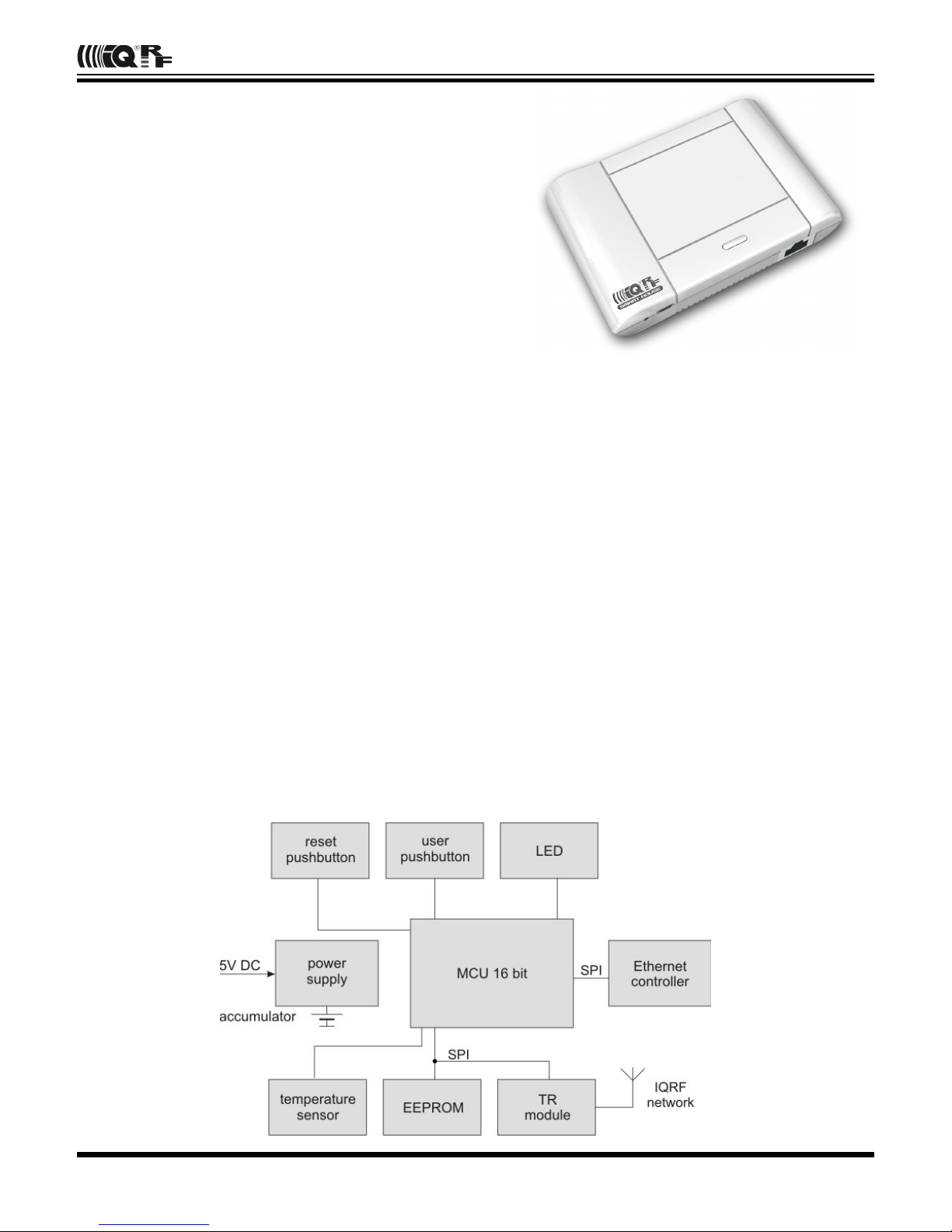
Description:
GW-ETH-01 is an IQRF gateway for connection between
IQRF and Ethernet networks allowing remote monitoring,
data collection and control of IQRF network.
Main components are: 16b microcontroller, Ethernet
controller, EEPROM memory, temperature sensor, IQRF
transceiver module with antenna and backup accumulator.
The GW can communicate outside the IQRF network via
Ethernet. Configuration is possible via internal www server
or from PC software GW-ETH Tool which can serve as a
test tool and allows remote upgrade of GW firmware and
upgrade of the application in internal TR module. A PC
program written by the user can also be used. The
application protocol is fully documented.
Applications:
• Remote monitoring and control
• Data acquisition
• Datalogger
• Interface to building / home automation
• Connection of more IQRF networks to single PC
• Acces to IQRF network from more locations
• Time synchronization from time servers
Key features:
• UDP server/client for communication with IQRF network
• HTTP/HTTPS server for remote management
• DDNS support
• SNTP client for getting date and time from Internet
• ICMP server allowing „ping“ to the equipment
• DHCP client for automated getting of IP address
• NBNS server for using names instead of IP addresses
• RTCC (real time clock/calendar)
• Backup accumulator
• Wall assembly option
• Very low power consumption in Sleep mode
• Documented application protocol
• Firmware upgrade via Internet
• Upgrade of application in internal TR module via Internet
Block schematics:
Page 3
GW-ETH-01
Electrical specifications (typical values unless otherwise stated)
Power supply 5.0 ± 0.35 V DC
Accumulator AL14500-700-1L, 3.7 V, 700 mAh, Li-Ion, AA
Supply current from external source
operational 175 mA (accumulator charged)
450 mA (accumulator discharged)
Supply current from accumulator
operational 160 mA
28 mA (Ethernet controller disabled)
Standby 10 µA (all peripherals disabled)
Temperature range 0 °C to +70 °C
Frequency range 868 MHz or 916 MHz (SW selectable)
RF output power 1.3 mW
Supported TR modules TR-52B or higher. TR-31B is also possible.
Antenna On-board diplole, soldered
EEPROM memory Capacity 64 kb, serial interface SPI, 1 000 000 erase/write cycles typ.
Ethernet 10Base-T
Dimensions 120 mm x 80 mm x 28 mm
Weight 115 g (including TR module and accumulator)
Absolute maximum ratings
Stresses above those values may cause permanent damage to the device. Exposure to maximum rating conditions
for extended periods may affect device reliability.
Supply voltage (VCC): 5.5 V
Storage temperature: -50 °C to +100 °C
Hardware
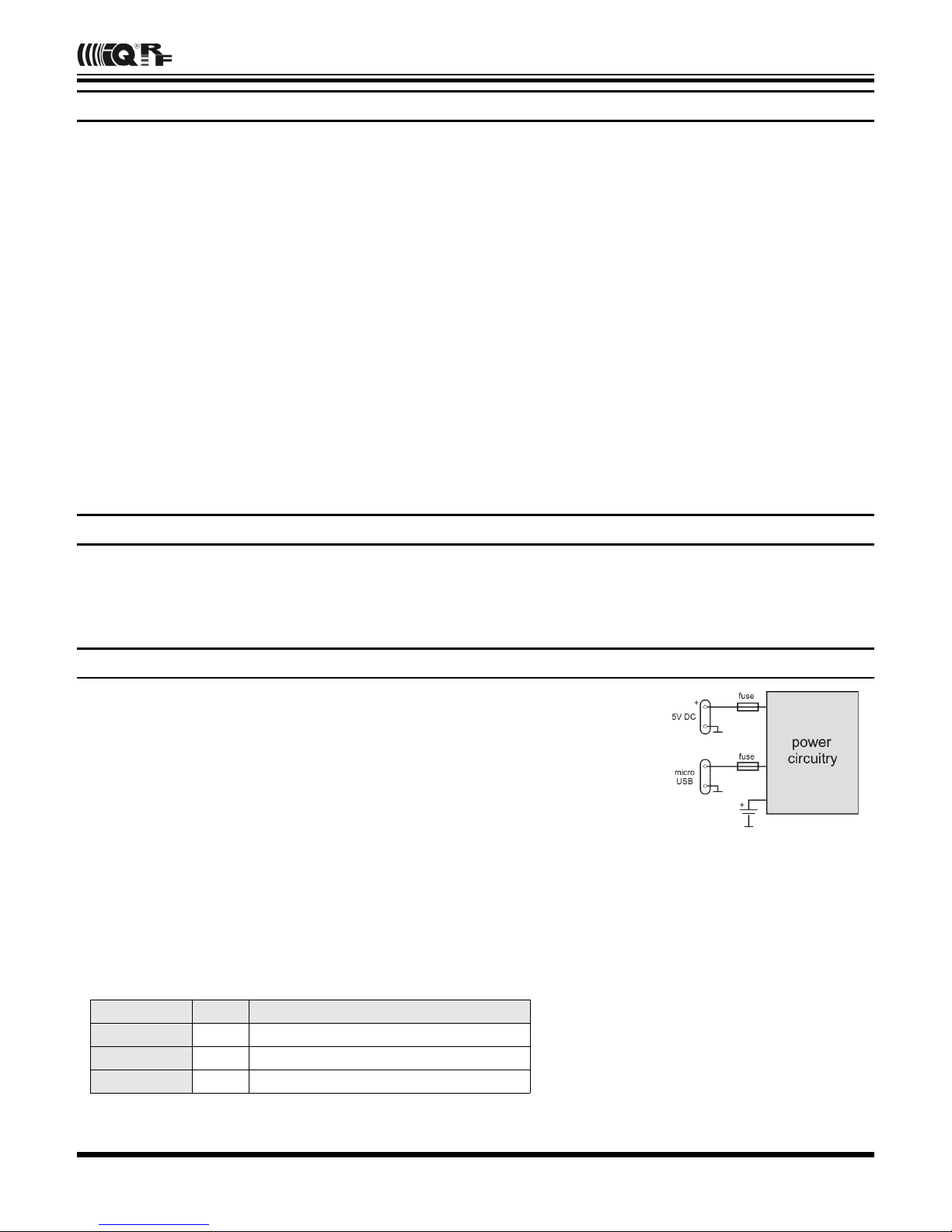
Power supply
GW-ETH-01 is intended to be supplied by external stabilized 5 V DC connected to
clamp or to micro USB connector. If both are connected, the internal logic gives
priority to the supply from the clamp. Accumulator serves as a backup for external
power source and should be charged from it.
Standby mode
The GW is turned off by switching to the Standby mode – see Control pushbuttons below. All peripherals are disabled
and power consumption is minimized in this mode. Wake-up follows after reset or connecting of external power.
Powering from accumulator is controlled as follows:
• if external voltage < 3.70 V then the Ethernet controller is disabled (reenabled after external power connecting)
• if external voltage < 3.45 V then the GW is switched to Standby mode
© 2011 MICRORISC s.r.o. www.iqrf.org MNGWETH01_110218 Page 3
The cable can be connected to the clamp
connector after breaking the molded cover at the
bottom of the case.
Connectors
connector pins type
External power 2 Micro USB and the clamp connector
Ethernet 8 RJ45
Accumulator 2 Soldering stripes
Page 4

GW-ETH-01
Control
Pushbuttons
Reset
• Simple press: GW reset (initialization)
• Press simultaneously with the User pushbutton (until indicated): bootloader mode
User pushbutton
• Short press: no effect
• Long press > 3s (if powered from the accumulator only): switching to the Standby mode
• Long press > 10s: configuration setup to factory values (even in bootloader mode)
• Press simultaneously with the Reset pushbutton (until indicated): bootloader mode
LED indication
GW contains one dual-color (red/green) service LED inside the case.
Legend:
• Reset
1s 200 ms / 200 ms for 3s
• Bootloader
1s 100 ms / 100 ms when in bootloader mode
• Operation, powered from external source
500 ms / 1100 ms period
• Operation, powered from accumulator
100 ms / 1500 ms period
• Switching to the Standby mode
1 s
© 2011 MICRORISC s.r.o. www.iqrf.org MNGWETH01_110218 Page 4
correct operation
failure: no time information
correct operation
failure: no time information
red
green
yellow
Page 5

GW-ETH-01
Operation
GW firmware includes the bootloader (BL) and the GW operational program.
BL contains:
• UDP server/client for upgrade of GW firmware
• ICMP server allowing “ping” to GW from a remote host
GW operational program contains:
• UDP server /client for communication with IQRF network and for remote GW management
• HTTP/HTTPS server offering web pages for remote management via a common browser
• HTTP client for getting and updating of public address from DDNS
• SNTP client for getting date and time from time server
• ICMP server allowing “ping” to GW from a remote host
• DHCP client for automated getting of IP address from the DHCP server
• NBNS server for using names instead of IP addresses within the LAN
MAC address
Every device has a unique MAC address in the format 00 1F D5 xx xx xx, where:
• 00 1F D5 is the OUI dedicated to MICRORISC s.r.o.
• xx xx xx is a device serial number
Actual MAC address is printed on the label at the bottom of the GW-ETH-01 case.
Modes of communication with internal IQRF module:
Three communication modes are available:
• Whole packet
According to the IQRF SPI protocol, the whole packet intended for the IQRF module must be created by the host.
The GW transfers this to the module without changes. The same goes for a packet received by the host.
• Only user data
The host sends only it's own data to the IQRF module in this mode. Packet creation according the IQRF SPI
protocol is up to the GW. The same goes for a packet received by the host from the GW.
• Datalogger
It is not possible to communicate externally with the TR module inside the GW in the Datalogger mode. GW
communication with the IQRF network depends on the application in internal TR module. All data sent via SPI from the
TR module to the GW are stored in circular buffer in the GW. Every packet is equipped with numeric code and time
stamp. Data can be freely read from this buffer via the HTTPS interface or user data can be sent via HTTPS to the TR
module. Refer to the Datalogger User's guide for more information.
Date and time
The GW contains the real time RTCC module which can be configured in several ways:
• From Internet time server via the SNTP protocol. Updated every 60 s.
• Manually from the GW web interface.
• Using the GW-ETH-01 Tool PC software.
This state is indicated as a failure until the GW gets the time info after a reset. See LED indication.
Safe Mode
If this mode is activated the GW does not respond to several commands via the UDP channel (exact list see the Application
protocol below). Full communication and GW configuration as well as repeated disabling the Safe Mode is possible via
HTTPS only.
© 2011 MICRORISC s.r.o. www.iqrf.org MNGWETH01_110218 Page 5
Page 6
GW-ETH-01
Factory setup
This initial setup can be restored whenever (in both GW and BL modes). This can be useful if it is not possible to establish
communication due to wrong configuration.
• NBNS name „iqrf“
• Get IP address from DHCP server automatically on
• IP address 192.168.0.254
• Subnet mask 255.255.255.0
• Gateway 192.168.0.1
• Primary DNS server: 192.168.0.1
• Secondary DNS server 0.0.0.0
• Authorization when enter the internal www page
• username „iqrf“
• password „iqrf“
• DDNS off
• Getting date and time from the time server on
• Time server europe.pool.ntp.org
• Summer / winter time distinguishing on
• Time zone (GMT+01:00) Prague
• Type of communication with the TR module Whole Packet
• GW port for the application protocol 55300
• Host port for the application protocol 55000
Firmware upgrade
The bootloader is a part of the GW software allowing to upload new firmware versions (delivered by the GW manufacturer)
to the GW by the user. The GW-ETH-01 Tool is a PC software intended for it. The BL mode can be also entered manually
(see Control pushbuttons). GW remains in the BL mode for 20 s. If no upgrade is started in this period the GW mode will be
reestablished. After upgrading the GW mode will be entered automatically. If the communication fails during the upgrade
the device is reset and stays in the BL mode. The GW uses the same network setup like in the GW mode (stored in
EEPROM) which is important for keeping the communication in case of remote upgrade. No setup changes are allowed in
the BL mode. In need, factory values can be setup manually (see Factory setup).
MAC address of given device is included in the BL. Thus, the device has the same MAC address after the upgrade.
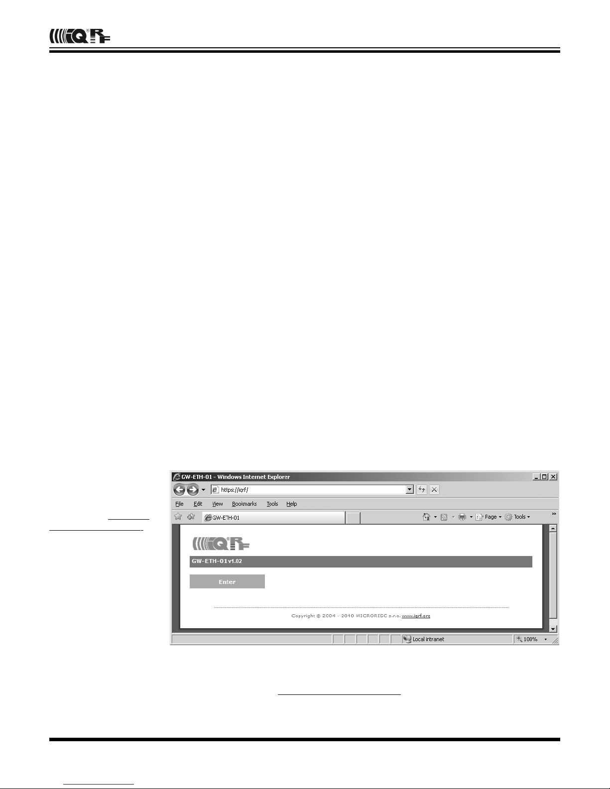
Connection to internal www pages in local network
Internal web interface is intended for configuration and monitoring of the GW state. Changes should be done by the skilled
person only. Possible problems in wrong setup can be solved by restoring the factory values.
The GW must be switched
on and connected to local
LAN network. The following
text assumes the factory
setup. Enter „https://iqrf“ or
„ https:// <ip_address>“
respectively. The page
depicted below will appear.
Click the Enter button and
enter login data (login
name as well as the
password are „iqrf“).
Working with the pages are
intuitive, the state of the
device can be monitored
and all its parameters can
be setup there.
GW-ETH Tool
The GW-ETH Tool program is free to download from http://www.iqrf.org/downloads. The handling is intuitive, additionally
the Help is available. This tool offers the same possibilities for monitoring and configuration of the equipment like internal
www server and additionally the following functions are available:
© 2011 MICRORISC s.r.o. www.iqrf.org MNGWETH01_110218 Page 6
Page 7

GW-ETH-01
• The Terminal tab enables communication with the TR module and then with the IQRF network via a terminal window
(like in the IQRF IDE).
• The Upload tab enables to upgrade the firmware of the equipment (coded file .CHX) or to change the application in the
TR module (file .HEX or coded file .IQRF).
• The Communication tab displays all communication with the equipment and offers a useful tool for development and
debugging of the user software communicating with the GW.
• The program allows communication using text files. It can send a packet from and save received packet to a text file.
This can be useful for users not being able to program the UDP communication but familiar with opening / saving files.
See the GW-ETH Tool Help for more information.
IQRF DNS
IQRF DNS server is provided by the MICRORISC s.r.o. and is intended as a replacement of the The Dynamic DNS server.
It allows users a remote connection to an eqiupment (within Internet) without knowing current public IP address of the
equipment. If the equipment is configured and local redirection is set properly it is possible to use the IQRF DNS names
instead of IP addesses of the equipment in web browsers - see the example below. The only thing what the user should
know is the MAC address of the equipment. The same approach can be applied also in case of the GW-ETH-Tool program.
Fof details see the GW-ETH Tool Help. In following explanation the MAC address 001FD5010203 and IP address
10.100.20.200 are used.
Registering the equipment in the IQRF DNS server database http://www.iqrfdns.org/?IDIP=001FD5010203
The GW-ETH-01 client sends this command automatically and regularly (if this is activated in the GW setup) which keeps a
record of MAC address of the equipment and corresponding IP address (for remote GW connecting) in the server
database. The server responds with public IP address which the command was sent from. Thus, the equipment finds out its
public IP address in the format:
Current IP Address: 10.100.20.200
Request for IP address http://www.iqrfdns.org/?IP=001FD5010203
The http client of the GW-ETH Tool program sends this command to find out the IP address assigned to given MAC
address in the server database. The server returns the result in the format:
Requested IP Address: 10.100.20.200
If the MAC address is not found in the database the server returns:
IQRFDNS Message: Reguested device is not registered.
Connection to the equipment - redirection http://www.iqrfdns.org/?ID=001FD5010203
The command is intended to be entered to the www browser for connection to www interface of the GW-ETH-01. The
server finds requested ID (MAC address) in the database and redirects it to assigned IP address. The GW must have set
and activated the IQRF DNS server as the DDNS.
If requested ID is not found the server returns:
IQRFDNS Message: Reguested device is not registered.
If there is no answer from the GW after redirection the server returns:
IQRFDNS Message: Device is not responding. It is either offline or its IP address has changed. Try it again after xx:xx min.
GW usage
GW-ETH-01 can communicate outside the IQRF network via Ethernet using internal www server, the GW-ETH Tool or a
PC program written by the user based on the open application protocol using the UDP transport level.
© 2011 MICRORISC s.r.o. www.iqrf.org MNGWETH01_110218 Page 7
Page 8

GW-ETH-01
Application protocol
The communication is realized with the application protocol described below. It uses the transport protocol UDP according
the OSI reference model. For establishing a connection it is necessary to know the UDP port where the GW is listening and
its IP address or the NetBIOS name (Host Name).
GW answers and response to commands to any asking device. Asynchronous messages are sent to broadcast address
until the communication is established. After communication establishing the messages are sent to address of the last
communicating host. Thus, more hosts (e.g. servicing programs on more PCs) can communicate with the GW.
If the IP address or NetBIOS of the GW and the port number are known it is just possible to establish the connection.
Otherwise the request for a GW identification can be sent to broadcast address (in a single LAN segment only – routers
filter packets with broadcast addresses.) All GWs receiving this request will answer which allows to get actual IP address of
given GW.
Packet description
The packet structure is the same for both communication directions:
HEADER (H = 9 B) DATA (D = 0 – 497 B) CRC (2 B)
For receiving, GW checks:
• GW_ADR validity – see the packet header
• packet length must not be lower than HEADER + CRC
• packet length must not be higher than HEADER + DATA MAX + CRC
• CRC
Header
Packet header has a fixed length:
0 1 2 3 4 5 6 7 8
GW_ADR CMD SUBCMD RES RES PACID_H PACID_L DLEN_H DLEN_L
GW_ADR identification address of the equipment of the GW-ETH-01 type (value: 0x22)
CMD command of a packet (values: 0x01 … 0x7F)
answer to given command: CMD = CMD | 0x80 (bit 7 of given CMD set)
SUBCMD auxiliary information of a command (values: see description below)
RES reserved
PACID_H packet identification – upper byte (values: 0x00 … 0xFF)
PACID_L packet identification – lower byte (values: 0x00 … 0xFF)
DLEN_H data length – upper byte (values: 0x00, 0x01)
DLEN_L data length – lower byte (values: 0x00 … 0xFF)
The packet identification (PACID) can be any number 0x0000 – 0xFFFF according to the host specification. The GW
always copies this number to the answer to given packet.
CRC
The check part has a fixed length:
H+D H+D+1
CRC_H CRC_L
CRC type CRC-16-CCITT
Polynomial 0x1021 (x^16 + x^12 + x^5 + 1)
Initial value 0x0000
CRC is calculated from the HEADER and DATA parts.
© 2011 MICRORISC s.r.o. www.iqrf.org MNGWETH01_110218 Page 8
Page 9

GW-ETH-01
Communication initiated by the host (e.g. GW-ETH Tool)
Get GW identification
Getting a GW identification. It is intended to identification of the GW which the connection is established with.
host -> GW direction
CMD 0x01 returns the GW identification
SUBCMD 0x00 no information
DLEN 0x0000 no data
GW -> host direction
CMD 0x81 answer to the 0x01 command
SUBCMD 0x00 no information
0x10 bootloader
DATA text with GW identification. See Data identification
-------------------------------------------------------------------------------------------------------------------------------------
Get GW status
The GW returns the information about its state.
host -> GW direction
CMD 0x02 returns the GW status
SUBCMD 0x00 no information
DLEN 0x0000 no data
GW -> host direction
CMD 0x82 answer to the 0x02 command
SUBCMD 0x00 no information
DATA see Status data
-------------------------------------------------------------------------------------------------------------------------------------
Write data to TR module
Data according the IQRF SPI protocol is written to the TR module. The answer is an acknowledge of writting to the module.
If the answer is requested from the module it is sent with the actual command – see Communication initiated by the GW.
According to GW configuration either just actual data or the whole packet is written.
host -> GW direction
CMD 0x03 write data to the TR module
SUBCMD 0x00 no information
DATA data for the TR module
GW -> host direction
CMD 0x83 answer to the 0x03 command
SUBCMD 0x50 write OK
0x60 write Error (number of data = 0 or more than TR buffer COM length)
0x61 write Error (SPI bus busy)
0x62 write Error (IQRF - CRCM Error)
DLEN 0x0000 no data
-------------------------------------------------------------------------------------------------------------------------------------
Read GW configuration
Reading of configuration parameters from EEPROM in GW.
host -> GW direction
CMD 0x06 reading of GW configuration
SUBCMD 0x00 no information
DLEN 0x0000 no data
GW -> host direction
CMD 0x86 answer to the 0x06 command
SUBCMD 0x00 no information
DATA see Configuration data
-------------------------------------------------------------------------------------------------------------------------------------
© 2011 MICRORISC s.r.o. www.iqrf.org MNGWETH01_110218 Page 9
Page 10

GW-ETH-01
Write GW configuration
Writting of configuration parameters to EEPROM in GW.
host -> GW direction
CMD 0x07 write GW configuration
SUBCMD 0x00 no information
DATA see Configuration data
GW -> host direction
CMD 0x87 answer to the 0x07 command
SUBCMD 0x50 write OK
0x60 write Error (invalid number of configuration bytes)
DLEN 0x0000 no data
-------------------------------------------------------------------------------------------------------------------------------------
Write to RTCC in GW
Writing of time and date to the RTCC in GW
host -> GW direction
CMD 0x08 write to RTCC
SUBCMD 0x00 no information
DB1 GW time – seconds (values see Time and data coding)
DB2 GW time – minutes
DB3 GW time – hours
DB4 GW data – day of week
DB5 GW data – day
DB6 GW data – month
DB7 GW data – year
GW -> host direction
CMD 0x88 answer to the 0x08 command
SUBCMD 0x50 write OK
0x60 write Error (invalid values)
DLEN 0x0000 no data
-------------------------------------------------------------------------------------------------------------------------------------
Change autentization
Changing of username and password for access to GW via www.
host -> GW direction
CMD 0x09 change autentization
SUBCMD 0x00 no information
DB1 username: text
to (max. 15 characters, not used ones replace with zeroes)
DB15
DB16 old password: text
to (max. 15 characters, not used ones replace with zeroes)
DB30
DB31 new password: text
to (max. 15 characters, not used ones replace with zeroes)
DB45
GW -> host direction
CMD 0x89 answer to the 0x09 command
SUBCMD 0x50 write OK
0x60 write Error (invalid old password)
DLEN 0x0000 no data
-------------------------------------------------------------------------------------------------------------------------------------
© 2011 MICRORISC s.r.o. www.iqrf.org MNGWETH01_110218 Page 10
Page 11

GW-ETH-01
Read TR Module Info in GW
Getting information about the module in the GW
host -> GW direction
CMD 0x11 read the TR Module Info from the GW
SUBCMD 0x00 no information
DLEN 0x0000 no data
GW -> host direction
CMD 0x91 answer to the 0x11 command
SUBCMD 0x00 no information
DATA see Module Info
-------------------------------------------------------------------------------------------------------------------------------------
Reset GW (GW as well as the bootloader)
Remote GW reset (initialization).
host -> GW direction
CMD 0x12 GW reset
SUBCMD 0x00 no information
DLEN 0x0000 no data
GW -> host direction
See Communication initiated by the GW – Sending the GW status message.
-------------------------------------------------------------------------------------------------------------------------------------
TR module reset
Remote reset of the TR module.
host -> GW direction
CMD 0x13 TR module reset
SUBCMD 0x00 no information
DLEN 0x0000 no data
GW -> host direction
CMD 0x93 answer to the 0x13 command
SUBCMD 0x50 OK command
0x60 Error command
DLEN 0x0000 no data
-------------------------------------------------------------------------------------------------------------------------------------
Sending a command not implemented in GW
host -> GW direction
CMD ? unknown command
SUBCMD ? arbitrary information
DATA arbitrary data
GW -> host direction
CMD ? | 0x80 answer to an unknown command
SUBCMD 0x60 packet error
DLEN 0x0000 no data
-------------------------------------------------------------------------------------------------------------------------------------
© 2011 MICRORISC s.r.o. www.iqrf.org MNGWETH01_110218 Page 11
Page 12

GW-ETH-01
Communication initiated by the GW (asynchronous message)
Send date from TR module
Sends data from the TR module according to the IQRF SPI protocol. According to the settings either just actual data or the
whole packet is send.
GW -> host direction
CMD 0x04 send data from TR module
SUBCMD 0x00 no information
DATA data from TR module
-------------------------------------------------------------------------------------------------------------------------------------
Send GW status message
It is a message from the GW about its state. The information is indicated by the SUBCMD byte.
GW -> host direction
CMD 0x05 GW status message
SUBCMD 0x01 GW reset, sent after switching on
0x02 change its own IP address (only if the DHCP is active)
0x03 power supply: external
0x04 power supply: acumulator
0x10 reserved for upgrade (sent by the bootloader only)
DATA text with GW identification. See Identification data.
-------------------------------------------------------------------------------------------------------------------------------------
Identification data
Identification data consists of several texts separated by 0x0D 0x0A.
1. - GW name e.g.: „GW-ETH-01“
2. - GW version e.g.: „v0.30b“
3. - MAC address e.g.: „00 11 22 33 44 55“
4. - TCP/IP Stack version e.g.: „v4.51“
5. - IP address of GW e.g.: „192.168.2.100“
6. - Net BIOS Name e.g.: „iqrf “ 15 characters
7. - IQRF module OS version e.g.: „v2.08“
8. - Public IP address e.g.: „213.214.215.120“
-------------------------------------------------------------------------------------------------------------------------------------
Status data
GW status data for the Get GW status command.
DB1 TR module status (see the IQRF SPI protocol)
DB2 GW temperature – value in Celsius grads (signed char)
DB3 0x00 supplied from accumulator
0x01 supplied from external source
DB4 GW time – seconds (see Time and date coding)
DB5 GW time – minutes
DB6 GW time – hours
DB7 GW date – day of the week
DB8 GW date – day
DB9 GW date – month
DB10 GW date – year
DB11 GW accumulator voltage – H byte in mV (unsigned integer)
DB12 GW accumulator voltage – L byte
-------------------------------------------------------------------------------------------------------------------------------------
© 2011 MICRORISC s.r.o. www.iqrf.org MNGWETH01_110218 Page 12
Page 13

GW-ETH-01
Configuration data
GW configuration data for reading and writing to GW.
DB1 … M byte of GW IP address
DB2 … .
DB3 … .
DB4 … L byte of GW IP address
DB5 … M byte of Subnet Mask IP address
DB6 … .
DB7 … .
DB8 … L byte of Subnet Mask IP address
DB9 … M byte of Gateway IP address
DB10 … .
DB11 … .
DB12 … L byte Gateway IP address
DB13 … M byte of Primary DNS Server IP address
DB14 … .
DB15 … .
DB16 … L byte of Primary DNS Server IP address
DB17 … M byte of Secondary DNS Server IP address
DB18 … .
DB19 … .
DB20 … L byte of Secondary DNS Server IP address
DB21 0x00 … DHCP Disabled
0x01 … DHCP Enabled
DB22 … NetBIOS name: text
to … (max. 15 characters, not used ones replace with zeroes)
DB36 …
DB37 0x00 … communication with TR module – whole packets according to the IQRF SPI protocol
0x01 … communication with TR module – user data only
0x02 … communication with TR module – Datalogger Mode
DB38 … local UDP of GW port – H byte
DB39 … local UDP of GW port – L byte
DB40 … remote UDP of GW port – H byte
DB41 … remote UDP of GW port – L byte
DB42 0x00 … DDNS Client off
? … DDNS Client - polling period 1 – 255 min
DB43 … DDNS domain name: text
to … (max. 30 characters, not used ones replace with zeroes)
DB72 …
DB73 … DDNS user name: text
to … (max. 15 characters, not used ones replace with zeroes)
DB87 …
DB88 … DDNS password: text
to … (max. 15 characters, not used ones replace with zeroes)
DB102 …
© 2011 MICRORISC s.r.o. www.iqrf.org MNGWETH01_110218 Page 13
Page 14

GW-ETH-01
DB103 0x00 … DDNS Provider Index: www.iqrfdns.org
0x01 … www.dyndns.org
0x02 … www.no-ip.com
0x03 … www.dnsomatic.com
DB104 0x00 … SNTP Disabled
0x01 … SNTP Enabled
DB105 0x00 … Daylight Savings Disabled
0x01 … Daylight Savings Enabled
DB106 0x00 … Time Server Index: pool.ntp.org
0x01 … europe.pool.ntp.org
0x02 … asia.pool.ntp.org
0x03 … oceania.pool.ntp.org
0x04 … north-america.pool.ntp.org
0x05 … south-america.pool.ntp.org
0x06 … africa.pool.ntp.org
DB107 … Time Zone Index see Time zone coding
DB108 … Datalogger Packet Size (1 - 41 B)
DB109 0x00 … Safe Mode Disabled
0x01 … Safe Mode Enabled
-------------------------------------------------------------------------------------------------------------------------------------
© 2011 MICRORISC s.r.o. www.iqrf.org MNGWETH01_110218 Page 14
Page 15

GW-ETH-01
Time zone coding
0x00 (GMT-12:00) 0x0B (GMT-02:00) 0x16 (GMT+05:45)
0x01 (GMT-11:00) 0x0C (GMT-01:00) 0x17 (GMT+06:00)
0x02 (GMT-10:00) 0x0D (GMT) 0x18 (GMT+06:30)
0x03 (GMT-09:00) 0x0E (GMT+01:00) 0x19 (GMT+07:00)
0x04 (GMT-08:00) 0x0F (GMT+02:00) 0x1A (GMT+08:00)
0x05 (GMT-07:00) 0x10 (GMT+03:00) 0x1B (GMT+09:00)
0x06 (GMT-06:00) 0x11 (GMT+03:30) 0x1C (GMT+09:30)
0x07 (GMT-05:00) 0x12 (GMT+04:00) 0x1D (GMT+10:00)
0x08 (GMT-04:00) 0x13 (GMT+04:30) 0x1E (GMT+11:00)
0x09 (GMT-03:30) 0x14 (GMT+05:00) 0x1F (GMT+12:00)
0x0A (GMT-03:00) 0x15 (GMT+05:30) 0x20 (GMT+13:00)
-------------------------------------------------------------------------------------------------------------------------------------
Time and date coding
For individual values the BCD code is used. The upper nibble (UN) menas tens and the lower nibble (LN) means units.
Example (seconds):
DB = 0x53 means 53 s
Legal ranges:
seconds UN = 0 – 5 LN = 0 – 9 min. 0 max. 59
minutes UN = 0 – 5 LN = 0 – 9 min. 0 max. 59
hours UN = 0 – 2 LN = 0 – 9 min. 0 max. 23
day UN = 0 – 3 LN = 0 – 9 min. 1 max. 31
month UN = 0 – 1 LN = 0 – 9 min. 1 max. 12
year UN = 0 – 9 LN = 0 – 9 min. 8 max. 99 (2008 - 2099)
day of week UN = 0 LN = 0 – 6 min. 0 max. 6 (0 – Sunday, 1 – Monday, ... )
These ranges are checked during writting to the GW. If out of range the packet with SUBCMD = write Error is returned.
-------------------------------------------------------------------------------------------------------------------------------------
Module Info data
Information about the TR module in the GW.
DB1 module ID – MSB
DB2 module ID
DB3 module ID
DB4 module ID – LSB
DB5 OS version (upper 4b: major version, lower 4b: minor version)
DB6 microcontroller type (2: PIC16LF88, 3: PIC16F886)
DB7 OS build: LSB
DB8 OS build: MSB
-------------------------------------------------------------------------------------------------------------------------------------
Commands blocked in Safe Mode
The following commands and functions are blocked in the Safe Mode when communicationg via the UDP channel. GW
return value is 0x60 in these cases.
0x07 write GW configuration
0x08 write to RTCC
0x09 change autentization
0x12 GW reset
0x13 TR module reset
TR module upload
GW upload
-------------------------------------------------------------------------------------------------------------------------------------
© 2011 MICRORISC s.r.o. www.iqrf.org MNGWETH01_110218 Page 15
Page 16

GW-ETH-01
Pack list
• GW-ETH-01, in Sleep mode
• Internal TR module TR-52B
• Accumulator (soldered)
• Power source TY-A6-microUSB (5V DC, 500 mA, stabilized, with micro USB connector)
• Printed Brief User's Manual
• CD with documentation:
• GW-ETH-Tool-102 ZIP PC SW for communication and GW configuration
• MNGWETH01 PDF GW-ETH-01 User's guide
• MNGWETH01DL PDF Datalogger User's guide
• GW-ETH-01-103_100622n CHX Firmware for MCU
Ordering code
• GW-ETH-01 IQRF Ethernet gateway
Firmware history
• v1.03 Plug-ins to TR modules supported. For GW-ETH Tool v 1.02.
• v1.02 Datalogger and Safe mode implemented.
• v1.01 First release.
Document history
• 110218 Updated for TR-52B. Bug in MAC address fixed.
• 100622 FW v1.03. Plug-ins to TR modules supported.
• 100113 Datalogger and Safe mode function added.
Intended for GW-ETH-01 FW v 1.02 and GW-ETH Tool v 1.01.
• 090601 IQRF DNS chapter enhanced, 2 pictures added, some texts slightly revised.
• 090408 First release.
© 2011 MICRORISC s.r.o. www.iqrf.org MNGWETH01_110218 Page 16
Page 17

GW-ETH-01
Sales and Service
Corporate office
MICRORISC s.r.o., Delnicka 222, 506 01 Jicin, Czech Republic, EU
Tel: +420 493 538 125, Fax: +420 493 538 126, www.microrisc.com
Partners and distribution
Please visit www.iqrf.org/partners
Quality management
ISO 9001 : 2000 certified
Complies with ETSI directives EN 30279 V.1.2.1:99, ETS 30683:97, ETSI EN 301489-1:00,
ETSI EN 300220-1:00, ETSI EN 300390-2V.1.1.1:00
Complies with FCC directives FCC CFR, Title 47, Part 15, Section 15.209, FCC CFR, Title 47, Part 15, Section 15.249
Complies with Directive 2002/95/EC (RoHS)
Trademarks
The IQRF name and logo are registered trademarks of MICRORISC s.r.o.
PIC, SPI, Microchip, RFM and all other trademarks mentioned herein are property of their respective owners.
Legal
All information contained in this publication is intended through suggestion only and may be superseded by updates
without prior notice. No representation or warranty is given and no liability is assumed by MICRORISC s.r.o. with respect to
the accuracy or use of such information.
Without written permission it is not allowed to copy or reproduce this information, even partially.
No licenses are conveyed, implicitly or otherwise, under any intellectual property rights.
The IQRF products utilize several patents (CZ, EU, US)
On-line support: http://iq-esupport.com
© 2011 MICRORISC s.r.o. www.iqrf.org MNGWETH01_110218 Page 17
 Loading...