

Page 1

IQRF
Quick Start Guide
For IQRF OS v3.07D and higher
For IQRF IDE v4.30 and higher
© 2015 MICRORISC s.r.o. www.iqrf.org Quick_Start_Guide_IQRF_ 150805 Page 1
Page 2

QUICK START
Contents
Components required....................................................................................................................................................3
Development hardware..................................................................................................................................................3
Development set..........................................................................................................................................................3
DCTR transceivers......................................................................................................................................................3
Programmer.................................................................................................................................................................3
End devices.................................................................................................................................................................4
USB device..................................................................................................................................................................4
Typical usage of kits......................................................................................................................................................5
First demonstration......................................................................................................................................................5
Point-to-point...............................................................................................................................................................5
Network.......................................................................................................................................................................5
Two application levels...................................................................................................................................................6
Data controlled, no programming................................................................................................................................6
C-programming, fully programmable...........................................................................................................................6
Development software...................................................................................................................................................7
PC software.................................................................................................................................................................7
IQRF IDE................................................................................................................................................................7
USB drivers............................................................................................................................................................7
CC5X......................................................................................................................................................................7
Text editor...............................................................................................................................................................7
Installation...................................................................................................................................................................7
Test..............................................................................................................................................................................7
Other PC programs operating with USB.....................................................................................................................7
IQRF IDE.....................................................................................................................................................................8
Programming and uploading procedure.................................................................................................................8
Other development, test and service utilities..........................................................................................................8
C-programming..............................................................................................................................................................9
Design steps................................................................................................................................................................9
Debug........................................................................................................................................................................10
Application examples................................................................................................................................................10
Quick start with HWP without programming.............................................................................................................11
Demo HWP vs. General HWP versions....................................................................................................................11
Limitations.............................................................................................................................................................11
Extensions............................................................................................................................................................11
DS-DPA-02 development set.....................................................................................................................................11
1. Preparation............................................................................................................................................................11
2. HWP upload.........................................................................................................................................................12
Creating Nodes.....................................................................................................................................................12
Creating the Coordinator......................................................................................................................................12
3. Bonding.................................................................................................................................................................13
4. Discovery...............................................................................................................................................................14
5. Examples...............................................................................................................................................................15
A. Pop-up menu...................................................................................................................................................15
B. Macros............................................................................................................................................................15
C. DPA packet arranged manually........................................................................................................................15
6. Unbonding.............................................................................................................................................................16
Unbonding a Node on the Coordinator side.........................................................................................................16
Unbonding a Node on the Node side...................................................................................................................16
Recommended documentation...................................................................................................................................17
Document history.........................................................................................................................................................17
© 2015 MICRORISC s.r.o. www.iqrf.org Quick_Start_Guide_IQRF_ 150805 Page 2
Page 3
QUICK START
How to start the first IQRF design
IQRF start-up is also illustrated on IQRF Video tutorial set.
Components required
Just the following tools are needed:
• HW: IQRF development set
• SW: IQRF Startup package (free) including IQRF IDE development environment
• PC: Windows Vista, Windows 7, Windows 8, Windows 8.1 or Windows 10
Development hardware
Development set
IQRF development set DS-START-04 (see below) or DS-DPA-02 (see chapter DS-DPA-02 development set)
contains all HW needed for effective start-up.
DCTR transceivers
RF transceiver modules DCTR-72DA fitting to SIM connector. They are fully programmable under IQRF OS operating
system and allow to utilize hardware profiles under DPA framework (see chapter Quick start with HWP without
programming) for applications without programming.
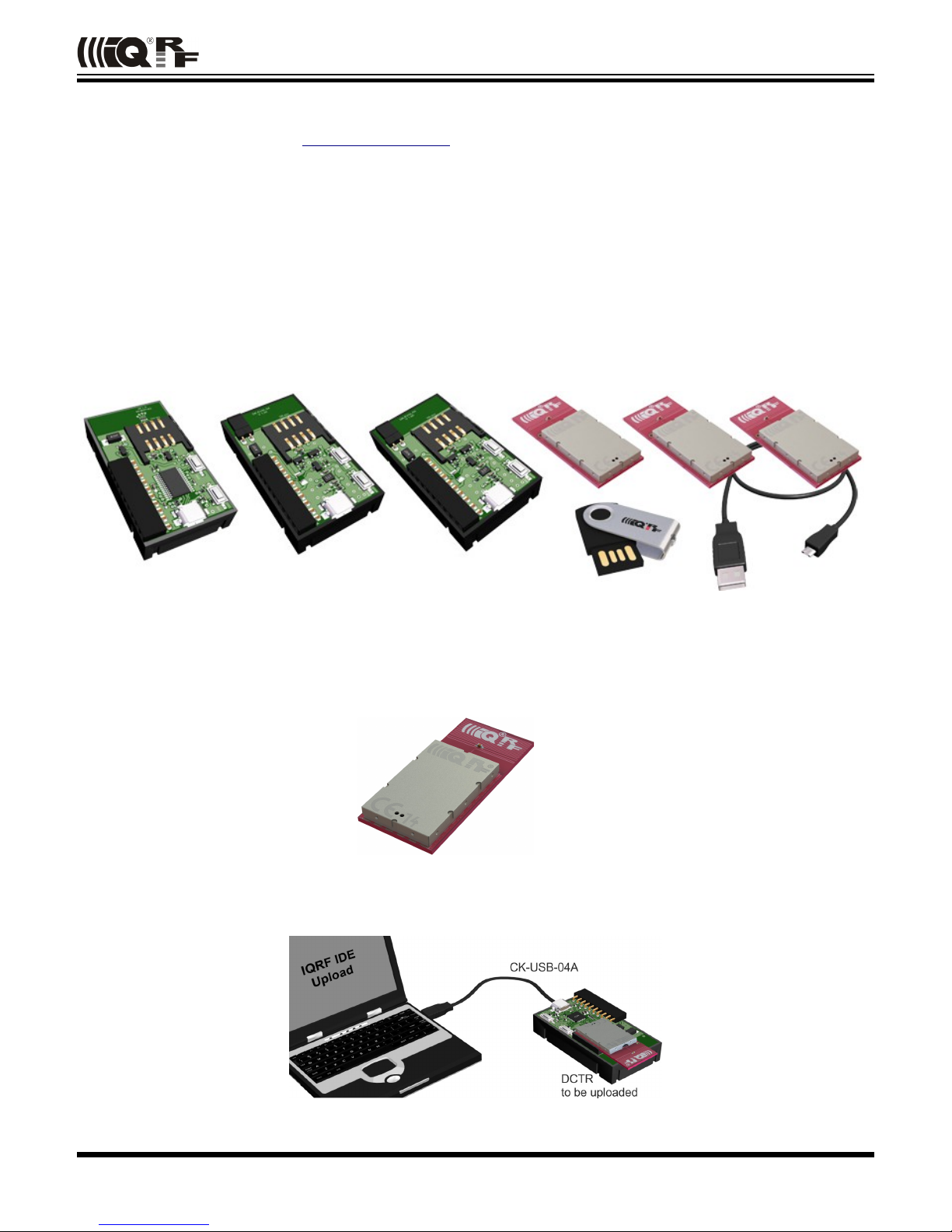
Programmer
To upload application codes in DCTRs and configure DCTR parameters, CK-USB-04A kit is intended.
© 2015 MICRORISC s.r.o. www.iqrf.org Quick_Start_Guide_IQRF_ 150805 Page 3
Page 4
QUICK START
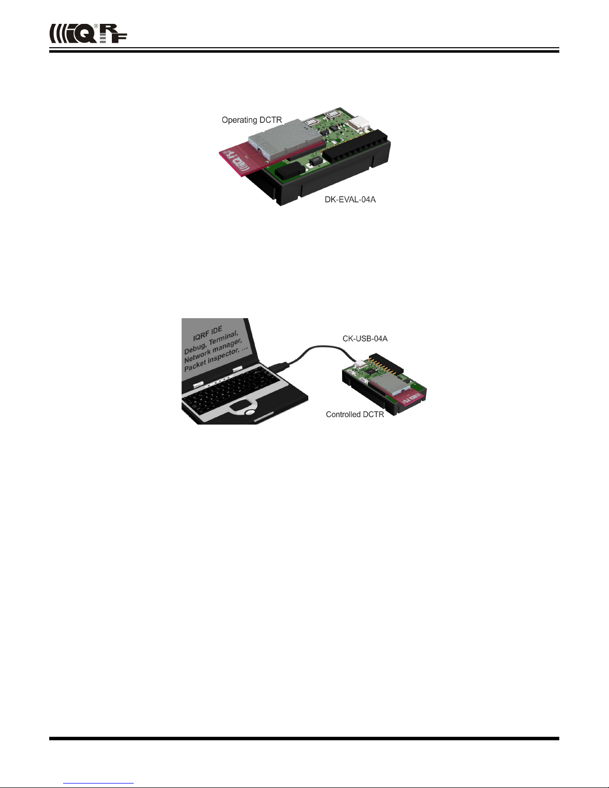
End devices
DCTRs (with application functionality codes uploaded using the programmer in advance) should be hosted in
portable DK-EVAL-04A kits.
USB connector is intended just for accumulator charging but not for USB connectivity.
USB device
DCTRs can also be hosted by CK-USB-04A connected to PC via USB. It enables to control the DCTR application
from PC, first of all by the IQRF IDE powerful tools for communication, testing, network management and
visualisation. This is advantageous especially for network Coordinator.
© 2015 MICRORISC s.r.o. www.iqrf.org Quick_Start_Guide_IQRF_ 150805 Page 4
Page 5

QUICK START
Typical usage of kits
First demonstration
RF link check:
• Unpack two DCTR transceivers from the development set. Do not make any changes in SW inside.
• Plug the TR modules to both DK-EVAL-04A kits and switch the power on by jumpers.
• Bidirectional RF link is automatically established between the kits. Red LED flashing indicates RF connection.
• You can move the kits and check RF link with respect to given environment.
Note: This link works plug and play thanks to the E09-LINK program which is uploaded in all TR modules in
development sets delivered from the factory. It is one of Basic examples from the Startup package and can be
uploaded whenever needed later on.
Point-to-point
Arrangement with two DK-EVAL-04A kits see above.
Arrangement with CK-USB-04A:
See Basic examples E01-TX, E02-RX, … in IQRF Startup Package.
Network
For networks, it is recommended to apply ready-to-use hardware profiles, which is much easier than writing one's
own user-specific application. See chapter Quick start with HWP without programming.
© 2015 MICRORISC s.r.o. www.iqrf.org Quick_Start_Guide_IQRF_ 150805 Page 5
Page 6

QUICK START
Two application levels
Specific functionality can be implemented into DCTR in one of the two application levels:
Data controlled, no programming
Higher level, running under DPA framework and utilizing so called Hardware profiles, which are ready-to-use SW
plug-ins enabling communication in mesh networks with no need of programming. DCTR is not controlled by an
application program but by data flow. All resources of given device are accessed via sending and receiving packets.
Requested functionality is achieved without programming. However, even this approach allows user-specific adapting
by optional Custom DPA handler programmable in C language.
C-programming, fully programmable
Lower level, running directly under IQRF OS. The functionality is given by the application program in C language.
This approach can be implemented also with TR transceivers (without the DC prefix, supporting only Demo hardware
profiles).
For network applications, using the DPA approach is highly recommended.
Although IQRF OS supports mesh networks by embedded IQMESH protocol with a set of powerful functions, more
detailed knowledge about IQRF and IQMESH is still needed for networking under IQRF OS.
To the contrary, the DPA framework utilized in DCTR transceivers solves the networking transparently. Just the
addressees must be specified and then the packets are delivered automatically. This, together with data controlled
approach with no programming needed makes DCTR very easy to implement. The entire network traffic is based on
simple commands only specifying where and what to perform.
© 2015 MICRORISC s.r.o. www.iqrf.org Quick_Start_Guide_IQRF_ 150805 Page 6
Page 7

QUICK START
Development software
All software and documentation is available in a single IQRF Startup package on the IQRF CD or USB Flash drive
included in the development set. The newest version should be downloaded from www.iqrf.org/startup.
PC software
IQRF IDE
Integrated development environment by MICRORISC to create, debug and control IQRF applications and manage
IQRF network. Required minimal IQRF IDE version depends on IQRF OS version of given TR transceiver and
possibly also on DPA version. See IQRF IDE Release notes. The best way is to always use the latest IDE version.
USB drivers
IQRF USB devices primarily utilize Custom class (with VID / PID by MICRORISC when used with IQRF devices).
Several IQRF USB devices (e.g. GW-USB-06) can also (optionally) use the CDC class. (CDC is not necessary for
IQRF startup.)
• USB drivers implemented in current IQRF devices (e.g. CK-USB-04A or GW-USB-06 with up-to-date firmware) are
by verified publisher based on the WinUSB by Microsoft.
• USB drivers implemented in older IQRF devices (e.g. CK-USB-04) or in older firmware versions of some current
devices are based on the MPUSB by Microchip.
CC5X
C compiler for the PIC microcontrollers (by B Knudsen Data). The evaluation version (included in IQRF Startup
package) is free. The compiler is not necessary when using hardware profiles without a Custom DPA handler.
Text editor
For source code creation and modification, any external editor beeing able to save a plain ASCII text, e.g. Windows
Notepad can be used. Notepad++ (a great source code editor, free by GPL License) is very recommended.
Download it from www.notepad-plus-plus.org. The editor is not necessary when using hardware profiles without a
Custom DPA handler.
Installation
1. Do not have any IQRF USB device connected.
2. Unzip the Startup package (the .zip file). All you need is automatically unpacked to specified directory.
3. Install the IQRF IDE by invoking the installation file iqrf-ide-4xx….exe in subdirectory IQRF_IDE. USB
drivers and free edition of the C compiler are also installed. Follow the instructions during installation. See the
IQRF USB drivers Installation guide (in subdirectory Documentation\SW) for details depending on Windows
version.
4. Connect the CK-USB-04A to PC.
5. Invoke the IQRF IDE.
6. To edit source C files, Windows native Notepad is set as default. You can change it for your favorite editor (e.g.
Notepad++) in the Tools / Options / Editors menu.
Up to 3 instances of IQRF IDE v4.xx are allowed running at the same time. But only one IQRF IDE can be installed.
Test
Open the default IDE project E00-START in the Examples/IQRF_OS/StartUp directory and press the F11 key
(USB Device / Indicate USB Device). LED1 on the CK-USB-04A should flash thrice which indicates correct connection
between CK-USB-04A and PC.
Other PC programs operating with USB
Other PC programs which utilize the same USB driver, e.g. IQRF UDU (obsolete) for upgrade a firmware in IQRF
devices, IQRF Router configurator or some 3rd-party SW (e.g. by Microchip), must not be running at the same time
with IQRF IDE.
© 2015 MICRORISC s.r.o. www.iqrf.org Quick_Start_Guide_IQRF_ 150805 Page 7
Page 8

QUICK START
IQRF IDE
IQRF IDE environment integrates all SW tools needed for application development (and a lot of utilities for following
control, maintenance and service). It is project oriented. Thus, a Project containing necessary definitions and files
must be specified first. Default Projects are available for immediate start. Project definition files have the iqrfprj
extension. See IQRF IDE Help for details.
Programming and uploading procedure
• Programming – creation of user specific IQRF application program.
• Editing – creation / modification of source code in C language. Not necessary when using hardware profiles without a
Custom DPA handler.
• Compilation – compiling the source program from C language to .HEX machine code. Not necessary when using
hardware profiles without a Custom DPA handler.
• Upload – uploading the code into the DCTR module (either a hardware profile, possibly with a Custom handler, or a
user-specific application). Wireless upload (RFPGM) is also possible – see IQRF OS User's guide and IQRF OS
Reference guide.
Other development, test and service utilities
• Debug – allows to stop program execution and watch internal variables (break, watch and continue).
• Terminal – utility to control serial communication.
• Packet inspector decoding and interpreting packets logged in Terminal Log window.
• Network management, visualization, testing, …
Tip: To switch the project from default (E00-START) to another existing example (e.g. E01-TX), replace the E00-
START.c and E00-START.hex files in the Project with E01-TX.c and E01-TX.hex and save the Project as
E01-TX (which creates the E01-TX.iqrfprj file).
© 2015 MICRORISC s.r.o. www.iqrf.org Quick_Start_Guide_IQRF_ 150805 Page 8
Page 9

QUICK START
C-programming
Programming in C language is needed:
• When DPA is used and given ready-to-use hardware profile has to be extended by a user-specific Custom DPA handler.
• When the application is written under IQRF OS, without DPA.
Programming in C language is not needed when DPA is used and some existing Custom handler is to be used or no
Custom handler is required at all.
If DPA is used, once the hardware profile is uploaded, it is not necessary to upload it any more when just the Custom
DPA handler is changed.
The Startup Package contains a demo Project, either for DPA (HWP-demo) or non-DPA (E00-START) approach and a
series of examples in the Examples/ subdirectories to be utilized as needed:
1. Using a ready-made example (without modifications): Add a .HEX file to the Project and upload it into DCTR
module plugged in CK-USB-04A by the F5 key (Programming/Upload). (This must be enabled in the Project
window.)
2. Using an example with possible modification: Add a source program (with the .C extension) to the Project,
make modifications by editing (if desired) and compile it from the C language to the HEX format by the F10 key
(Project/Build Target). Upload resulting .HEX file similarly as in the case 1 above.
3. Creation of a new program: Use the CustomDpaHandler-Template.c or Template.c empty source file
and continue similarly as in the case 2 above.
Refer to the IQRF IDE Help to learn about configuring the Project.
Design steps
1. Plug the TR into CK-USB-04A kit and run IQRF IDE.
2. Open a new Project (Project/New Project) and specify TR module type (Project/Properties/TR Module).
3. If you do not intend to modify or display a source code but to upload an existing code only, add required .IQRF or
.HEX file to the Project (Project/Add Existing Item) and go to step 7.
4. Add required source file (one of examples, e.g. CustomDpaHandler-Timer, E09-LINK.c or empty template
CustomDpaHandler-Template.c or Template.c to the Project (Project/Add Existing Item).
5. Make possible modifications and save them then (in the text editor).
6. Compile the program by the F10 key (Project/Build Target). If any error is reported by the compiler, go to step 5 to
correct it. The result is a compiled code in the .HEX format stored in the Project.
7. Program the code into the module by the F5 key (Programming/Upload).
8. After uploading the application is just invoked. It is possible to debug it by the IQRF IDE . See chapter Debug
below.
9. Then the transceiver can be carried e.g. to another development kit or to an end user equipment.
Typical repeated “loop” during development is: Edit, Save (Ctrl+S), Compile (F10), Upload (F5), Debug.
Refer to chapter DPA for detailed step by step instructions for DPA usage without programming..
Refer to the IQRF Video tutorial set and IQRF IDE training video .
Caution: The TR module can be plugged / unplugged into / from the SIM connector while powered off only.
Tip: In case of CK-USB-04A the SW2 pushbutton (the one closer to SIM connector) can be used for this. The TR
module is not powered while the SW2 pushbutton is held.
Note: The IQRF IDE reports a state of the TR module at the bottom bar of the main IDE window. T he SPI not active
message need not mean a missing or damaged TR. It is issued if SPI communication is not activated which depends
on the application running in the module. SPI communication can be forced by switching the TR module in the
programming mode by F6 key (Programming/Enter Programming Mode). The application in the TR module is not
running in the programming mode.
© 2015 MICRORISC s.r.o. www.iqrf.org Quick_Start_Guide_IQRF_ 150805 Page 9
Page 10

QUICK START
Debug
The operating system offers the debug() function to be placed in source code wherever you wish to stop and
display internal variables and registers. After selecting the Skip Breakpoint button the application continues running
until next debug() function is encountered and so on. If more debug instances is set at the same time, the W register
(MCU accumulator) should be used to distinguish the active breakpoint location. Macro breakpoint(w) can be
used for simplicity. See IQRF-macros.h header file and basic example E06-RAM for explanation.
Example
Application examples
The Startup Package contains demo programs:
• For DPA
• Custom DPA handler examples
• For non-DPA
• Basic To get familiar with simple TR operation and OS functions
• Advanced More complex
• DDC For IQRF DDC development kits
• IQMESH Networking
© 2015 MICRORISC s.r.o. www.iqrf.org Quick_Start_Guide_IQRF_ 150805 Page 10
Page 11

QUICK START
Quick start with HWP without programming
This chapter is intended as a step-by-step guide to get familiar with DPA and HWP. The process is the same for all
hardware profiles, either Demo HWP with common transceivers (TR) or General HWP with Data controlled transceivers
(DCTR).
Demo HWP vs. General HWP versions
Limitations
• Demo HWP is limited to max. 5 Nodes (with addresses 1 to 5). A node device having an unsupported address flashes
periodically red LED after reset.
• Some Custom DPA handler events are not supported. See IQRF DPA Technical guide for specification.
• Only one user peripheral PNum = 0x20 with one command PCmd = 0x00 is supported.
Extensions
• Demo HWP supports the PWM peripheral (simple pulse-width modulated digital output).
• Discovery and FRC processes are indicated by LEDs flashing by default.
DS-DPA-02 development set
To learn DPA usage, development set DS-DPA-02 can be used.
• DCTR-72DAT IQRF smart transceiver 6 pcs
• CK-USB-04A IQRF programmer and debugger 2 pcs
• DK-EVAL-04A Universal portable development kit for (DC)TR modules 4 pcs
• CAB-USBABMICRO Micro USB cable 18.5 cm 2 pcs
• USB flash drive Software and documentation 1 pc
1. Preparation
All SW, plug-ins, documentation etc. are available on the flash disk and on www.iqrf.org/downloads.
• Prepare 5 pieces of DCTR-72DAT with OS 3.07D or higher as Nodes and one DCTR-72DAT module with OS
3.07D or higher as the Coordinator.
• Prepare 4 (5) pieces of DK-EVAL-04A and 1 (2) piece(s) of CK-USB-04A.
• Install IQRF IDE 4.30 or higher. Refer to chapter Installation above.
• Launch IQRF IDE and open Project HWP-demo.iqrfprj from IQRF Startup package. All necessary files and
macros are included in the Project.
© 2015 MICRORISC s.r.o. www.iqrf.org Quick_Start_Guide_IQRF_ 150805 Page 11
Page 12

QUICK START
2. HWP upload
Creating Nodes
A. Plug a DCTR module in CK-USB-04A, select the DemoHWP-Node-STD-SPI_*.iqrf file in Project window and
click the Upload Plug-ins button on the Toolbar (or use the F5 key). The plug-in should be uploaded then.
B. Double-click on the configuration file DPA-config.xml in IDE Project window to open the TR Configuration
window. Make the following settings:
• Select desired RF channel (RF Channel A) in the OS tab.
• Select desired RX Filter in the HWP tab.
• For short range testing (within the room) select 15.
• For operating in real conditions select 0 (for TR-7xD) or 5 (for TR-5xD).
This settings must be the same in the entire network!
Do not change other parameters for now.
Save the configuration into the DCTR module by button Upload.
C. Plug this DCTR module in the DK-EVAL-04A kit.
Repeat steps A to C for all Nodes.
Creating the Coordinator
Use the same procedure but with the DemoHWP-Coordinator-STD-SPI_*.iqrf and DPA-config.xml files.
Then leave the DCTR module plugged in CK-USB-04A.
Warning: If you use a stronger filter during the development, do not forget to reduce it then in final application.
© 2015 MICRORISC s.r.o. www.iqrf.org Quick_Start_Guide_IQRF_ 150805 Page 12
Page 13

QUICK START
3. Bonding
To use DPA, all Nodes in the network must be bonded to the Coordinator. To get all nodes bonded, follow next
procedure:
A. All Nodes must be unbonded and located in direct RF range to the Coordinator before bonding (local bonding).
• In case the Node is already bonded the red LED once shortly flashes. Go to step Unbonding below in this
case.
• If the node is not bonded the red LED is flashing for 10 s and then the module falls into sleep.
B. The Coordinator may possibly have stored some bonded Nodes from previous DCTR module usage. Thus, such
bonding information should be cleared from the Coordinator memory first. Click the Clear All Bonds (in IQMESH
Network Manager window, tab Control → IQMESH). Number of bonded Nodes should be 0, see the screenshot
below.
C. Activate the Auto address checkbox. Thus, addresses will be assigned automatically in ascending order starting
from 1. Click the Bond Node button. The Coordinator stays cca 10 s in bond mode. During this period press the
SW1 pushbutton (the one close to USB connector) on the DK-EVAL-04A kit containing the Node you are just
going to bond. It is convenient to mark the assigned address on the DCTR module (e.g. by a label).
D. Repeat step C for all Nodes. It should result in 5 bonded Nodes according to the screenshot below.
© 2015 MICRORISC s.r.o. www.iqrf.org Quick_Start_Guide_IQRF_ 150805 Page 13
Page 14

QUICK START
4. Discovery
Discovery is a process that sets up network topology to be able to deliver data or commands to Nodes out of the
Coordinator direct range. Thanks to HWP just a couple of clicks and all is done. Discovered topology can directly be
reviewed in window IQMESH Network Manager, the Map View tab. Follow next steps to run Discovery and create
different types of topologies.
A. Place all Nodes close to the Coordinator and click the Discovery button (in window IQMESH Network Manager, the
tab Control → IQMESH). If all Nodes are in direct range to the Coordinator the Discovery should take a few seconds
only. Switch to the Map View tab after finishing Discovery. The topology like in the screenshot below should appear.
B. Place Nodes in longer distance between each other (with respect to current RX Filter selected in TR
Configuration). For test purpose it is recommended to reduce the range using a shielding, e.g. by inserting the kits
with DCTR modules into plastic bags with anti-static proofing.
D. Click the Discovery button. If not all Nodes are in direct range now, the Discovery process will take a bit longer.
The result can look like on the screenshot below:
Note
Displayed “topology” is only a tree visualization of parent Nodes (illustrating just the path which has been used to
discover individual Nodes) but not the routing structure. This does not mean that packets can be delivered through
displayed links only. Packets are delivered based on Directed flooding routing algorithm described in IQRF OS User
's guide.
© 2015 MICRORISC s.r.o. www.iqrf.org Quick_Start_Guide_IQRF_ 150805 Page 14
Page 15

QUICK START
5. Examples
A quick test of the network functionality can be performed by the pop-up menu (example A below). For detailed
testing of DPA commands the Terminal – DPA Test tool provides two ways how to set up a specific DPA command:
using macros (example B) or manual arrangement of DPA packet (example C).
A. Pop-up menu
For the simpliest checking, a command to switch the red LED On/Off on
selected Node can be immediately sent by clicking the left mouse button on
the symbol of given Node in the map.
The command currently selected in the DPA Test – Data to Send window can
be executed by the right mouse button click on the symbol of given Node in the
map and by selecting the Send Packet from DPA Test item. NADR is set
automatically according to selected Node.
B. Macros
Click on the particular macro and PNUM, PCMD, HWPID and DATA are automatically filled in. Then select Node
Address in NADR box (for Broadcast use address 0xFF) and click the Send button.
• Go to LED macros and click on macro Set LEDR on. To switch all LEDs on, fill in 0xFF in NADR and Click Send
button.
• Use various macros and Node addresses to test the functionality.
C. DPA packet arranged manually
To get better understanding of DPA packet structure, you can
also fill in the DPA packet manually. By clicking the right
mouse button to the area for selecting NADR, PNUM,
PCMD or HWPID, menu Predefined Addresses, Predefined
Peripherals, Predefined Commands or Predefined HWP is
displayed. These lists allow to select items defined by the
DPA specification and directly arrange the packet.
• From menu Predefined Addresses select Broadcast or
directly specify the address of given Node.
• From menu Predefined Peripherals select the LEDR
peripheral.
• From menu Predefined Commands select the Set on
command.
• From menu Predefined HWP select the To All HWP item.
• Click the Send button.
Test other peripherals and commands in the same way.
© 2015 MICRORISC s.r.o. www.iqrf.org Quick_Start_Guide_IQRF_ 150805 Page 15
Page 16

QUICK START
6. Unbonding
Unbonding a Node on the Coordinator side
• Select the desired address of the Node in the Address field (IQMESH Network Manager – the Control → IQMESH tab).
• If the network is not created yet or given Node is not reachable, activate the Only in Coordinator checkbox.
• Click the Unbond Node button.
Unbonding a Node on the Node side
• Press and hold button SW1 (close to USB connector).
• Shortly press button SW2. Green LED shines for about 2 s.
• Release the SW1 button immediately once the green LED stops shining.
• If the node is successfully unbonded, red LED is flashing and module falls asleep after 10 s.
Note
Besides of IQMESH Network Manager and DPA Test, IQRF IDE provides also further tools (Terminal Log and Packet
Inspector) for working with DPA especially for developers implementing or testing the DPA protocol. They are described in
IQRF IDE Help.
© 2015 MICRORISC s.r.o. www.iqrf.org Quick_Start_Guide_IQRF_ 150805 Page 16
Page 17

QUICK START
Recommended documentation
• IQRF Video tutorial set
• IQRF DPA Framework Technical guide. For DPA approach only.
• IQRF OS User's guide.
• IQRF OS Reference guide – description of IQRF OS functions. For non-DPA approach or for DPA with Custom DPA
handler only.
• SPI User's guide – implementation in IQRF TR modules. It is needed only if you design one's own SPI master to
communicate with the TR module.
• TR module datasheet
• User's guides of development kits used
• IQRF USB drivers Installation guide
Document history
• 150805 First release for IQRF Quick start guide merged with IQRF DPA Quick start guide.
Updated for (DC)TR-7xD transceivers, IQRF OS v3.07D, DPA v2.20 and IDE v4.30 or higher.
© 2015 MICRORISC s.r.o. www.iqrf.org Quick_Start_Guide_IQRF_ 150805 Page 17
Page 18

QUICK START
Sales and Service
MICRORISC s.r.o., Prumyslova 1275, 506 01 Jicin, Czech Republic, EU
Tel: +420 493 538 125, Fax: +420 493 538 126, www.microrisc.com
Partners and distribution
Please visit www.iqrf.org/partners
Quality management
ISO 9001 : 2009 certified
Trademarks
The IQRF name and logo and MICRORISC name are registered trademarks of MICRORISC s.r.o.
PIC, SPI, Microchip and all other trademarks mentioned herein are property of their respective owners.
Legal
All information contained in this publication is intended through suggestion only and may be superseded by updates
without prior notice. No representation or warranty is given and no liability is assumed by MICRORISC s.r.o. with respect to
the accuracy or use of such information.
Without written permission it is not allowed to copy or reproduce this information, even partially.
No licenses are conveyed, implicitly or otherwise, under any intellectual property rights.
The IQRF ® products utilize several patents (CZ, EU, US)
Web www.iqrf.org
E-mail sales@iqrf.org
On-line support support@iqrf.org
© 2015 MICRORISC s.r.o. www.iqrf.org Quick_Start_Guide_IQRF_ 150805 Page 18
 Loading...