

Page 1

DDC-SE-01
IQRF Development Daisy Chain
Sensor kit
User's Guide
© 2018 IQRF Tech s.r.o. www.iqrf.org User_Guide_DDC-SE-01_180918 Page 1
Page 2
DDC-SE-01
© 2018 IQRF Tech s.r.o. www.iqrf.org User_Guide_DDC-SE-01_180918 Page 2
Description
A sensor development kit for IQRF wireless applications
with transceiver modules (TR) plugged in DK-EVAL-04
kit. Compatible with other DDC (Development Daisy
Chain) kits.
Ready-to-use examples are available demonstrating how
to use I2C and Dallas 1-wire buses and A/D converter
inside TR to measure temperature, voltage etc.
Applications
• Development of IQRF applications
• I2C and Dallas 1-wire bus demonstration
• A/D measurement demonstration
Key features
• Compatible with other IQRF DDC kits
• Supplied from DK-EVAL-04
• I2C temperature sensor
• I2C bus connector to access external peripherals
• Dallas 1-wire temperature sensor
• Light intensity measurement using a photoresistor
• Voltage measurement using a potentiometer
• Internal voltage LDO regulator
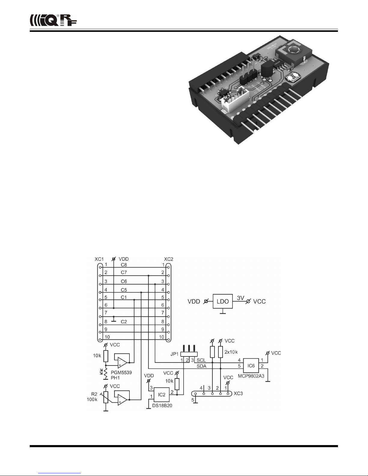
Simplified schematics
Page 3
DDC-SE-01
Electrical specifications (typical values unless otherwise stated)
Power supply (VDD) 3.2 V to 5.5 V DC
Internal supply voltage (VCC) 3 V
Supply current (when peripherals inactive) 650 µA
Temperature range 0 °C to +70 °C
Dimensions 48 mm x 27 mm x 11 mm
Weight 10 g
Absolute maximum ratings
Stresses above those values may cause permanent damage to the device. Exposure to maximum rating conditions for
extended periods may affect device reliability.
Supply voltage: 6.0 V
Storage temperature: -40 °C to +85 °C
Hardware
Power supply
DDC-SE-01 should be supplied from DK-EVAL-04 via connector XC2.
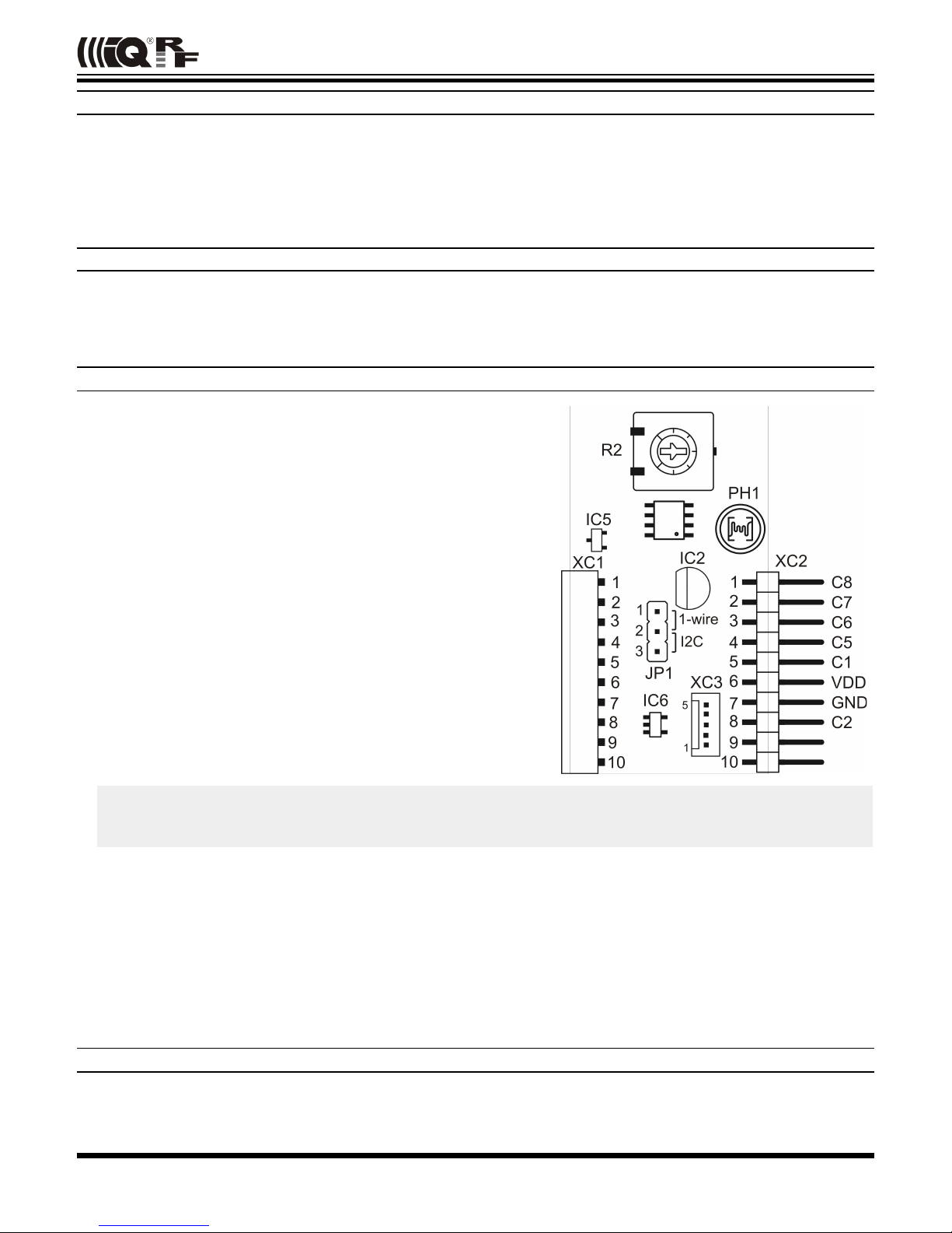
Interface connectors
The XC2 male connector with square 0.635 mm, 2.54 mm pitch pins
is intended for I/Os and power supply.
Corresponding XC1 female connector serves for interconnection with
other DDC kits.
XC3 is a 1.25 mm pitch miniature connector DF13C-5P (Hirose).
Mating Hirose cable connector: DF13-5S (plastic shell), DF13 crimp
contacts.
Internal peripherals
• I
2
C temperature sensor: MCP9802A3 (Microchip) with fixed I2C
slave address 10010110 (in binary).
• 1-wire temperature sensor: DS1820B20 (Dallas).
• Photoresistor: PGM5539 by Token. Resistance 30-90 kΩ at 10
lux, dark resistance 5 MΩ.
• Potentiometer: The potentiometer is intended for voltage
measurement using the A/D converter inside the MCU on the TR
transceiver.
Caution
To enable correct functionality of the pushbutton SW1 on the DK-EVAL-04(A) kit connected, the potentiometer shaft
must be in the intermediate position.
External I2C peripheral
• External I
2
C device should be connected via the XC3 connector. It must have I2C slave address different from 10010110
(in binary).
Jumper JP1
• In position 1 – 2 enables 1-wire sensor.
• In position 2 – 3 enables I
2
C temperature sensor and I2C external bus.
Refer to datasheets of used devices.
Software
Ready-to-use examples are available in the Startup package at www.iqrf.org.
© 2018 IQRF Tech s.r.o. www.iqrf.org User_Guide_DDC-SE-01_180918 Page 3
Page 4

DDC-SE-01
Product information
Pack list
• DDC-SE-01 DDC sensor kit
Recommended options
• DK-EVAL-04 IQRF development kit for TR modules
• DDC-IO-01 DDC input/output kit
• DDC-RE-01 DDC relay kit
• DF13-5S Cable connector fitting to XC3
• DF13 Crimp contacts for cable connector fitting to XC3
Ordering code
• DDC-SE-01 IQRF sensor DDC kit
Document history
• 180918 Photoresistor type changed. Chapter Potentiometer with the caution regarding the impact on
the pushbutton on DK-EVAL-01(A) added.
• 160203 The value of pull-up resistor on Dallas bus added to simplified schematics.
• 110415 First release
© 2018 IQRF Tech s.r.o. www.iqrf.org User_Guide_DDC-SE-01_180918 Page 4
Page 5

DDC-SE-01
Sales and Service
Corporate office
IQRF Tech s.r.o., Prumyslova 1275, 506 01 Jicin, Czech Republic, EU
Tel: +420 493 538 125, Fax: +420 493 538 126, www.iqrf.tech
E-mail (commercial matters): [email protected]
Technology and development
www.iqrf.org
E-mail (technical matters): [email protected]
Partners and distribution
www.iqrf.org/partners
Quality management
ISO 9001 : 2009 certified
Trademarks
The IQRF name and logo are registered trademarks of IQRF Tech s.r.o.
PIC, SPI, Microchip and all other trademarks mentioned herein are a property of their respective owners.
Legal
All information contained in this publication is intended through suggestion only and may be superseded by updates
without prior notice. No representation or warranty is given and no liability is assumed by IQRF Tech s.r.o. with respect to
the accuracy or use of such information.
Without written permission, it is not allowed to copy or reproduce this information, even partially.
No licenses are conveyed, implicitly or otherwise, under any intellectual property rights.
The IQRF ® products utilize several patents (CZ, EU, US)
On-line support: [email protected]
© 2018 IQRF Tech s.r.o. www.iqrf.org User_Guide_DDC-SE-01_180918 Page 5
 Loading...