

iQe Internal 15/26, Internal 26/35 Installation, Servicing And User Instructions Manual
Installation, Servicing & User Instructions
Oil Fired Condensing Boiler 15/26 Internal and 26/35 Internal
iQE Doc Hor15-35 01 V1.3 October 2013
Dear iQE Owner
Thank you for choosing an iQE boiler for your home heating. iQE is committed to
supplying quality products with a first class after sales service to all of our customers.
OUR SERVICE TO YOU
Your boiler is designed to give years of heating comfort. However any appliance, no matter
how well manufactured, can require repairs at some stage. For your peace of mind iQE have
continued investment and development to ensure it provides a dedicated nationwide team
of qualified engineers and a Customer Services Helpline.
BOILER REGISTRATION
For your safety, iQE requires that the boiler is installed by an appropriately qualified engineer
and the work registered with OFTEC Register within 30 days of completion*.
You will then receive notification to prove that this has been done. Your installer is also
required to complete the OFTEC CD10 in the Installation Guide provided with the appliance.
The installation also requires the completion of the CD11 (not supplied) at the time of
commissioning.
In order to maintain the warranty and to help ensure your boiler runs safely
and efficiently, it is required that your boiler is serviced annually.
Please refer to the terms and conditions for further clarification.
Andy Rudd
Commercial Director
*
I t is a legal requirement that an installation or change of a heating appliance is notified to the relevant
Local Authority, this requirement is met by the notification to the OFTEC Register or equivilant.

2
iQE Horizon Internal Oil Boiler
Subject PageSection
1 Introduction ............................................ 3
2
User instructions .................................. 4
3 Boiler technical information ........... 7
4
Gen
eral boiler information..................11
5 Con
densate disposal .......................... 27
6 Boiler installation
.................................. 31
7
Commissioning....................................... 37
8
Information for th
e user ....................38
9
Boiler servicing ..................................... 38
10
Wiring diagrams ...
................................ 42
11
Fault finding .......................................
......43
12
Boiler spares
.......................................... 45
13
Bu
rner spares ........................................ 46
14
Heal
th and safety information ....... 47
15
EC declaration of conformity
........ 48
Date: ..............................
Commissioning engineer: .............................................................................. Tel. No: ....................................
Boiler model/output: ........................................ kW Fu
el type: Kerosene
Nozzle size: .................................... Pump pressure: .................... Air setting: ...........................
Flue gas % CO2: ............................. Net flue gas temp:................ Smoke No:...........................
LIST OF CONTENTS
Warranty.....................................................49
SERVICE LOG
It is recommended that the boiler should be regularly serviced, at least once a year,
and the details recorded.
16
COMMISSIONING REPORT

3
During the combustion process, hydrogen and
oxygen combine to produce heat and water
vapour. The water vapour produced is in the form
of superheated steam in the heat exchanger. This
superheated steam contains sensible heat
(available heat) and latent heat (heat locked up in
the flue gas). A conventional boiler cannot
recover any of the latent heat and this energy is
lost to the atmosphere through the flue.
The iQE condensing boiler contains an extra
heat exchanger which is designed to recover the
latent heat normally lost by a conventional
boiler. It does this by cooling the flue gases to
below 90° C, thus extracting more sensible heat
and some of the latent heat. This is achieved by
cooling the flue gases to their dew point
(approximately 55° C).
To ensure maximum efficiency, the boiler
return temperature should be 55° C or less,
this will enable the latent heat to be
condensed out of the flue gases. The boiler will
achieve nett thermal efficiencies of
100%.
To achieve maximum performance from the iQE
Internal boiler, it is recommended that the
heating system is designed so that a
temperature differential of 20° C between the
flow and return is maintained. The use of
modulating circulating pumps (now widely
available) and effective control systems should
be considered.
Th
e iQE Internal boiler will however still operate
at extremely high efficiencies even when
it is not
in condensing mode and therefore is suitable for
fitting to an existing heating system without
alteration to the radiator sizes. The boiler is
capable of a maximum flow temperature of 75° C.
To achieve the maximum efficiencies possible
from the iQE boiler, the heating system should
be designed to the following parameters:
Radiators:-
Flow temperature 70° C
Return temperature 50° C
Differential 20° C
Underfloor:-
Flow temperature
50° C
Return
temperature
40° C
Differential
10° C
1 Size radiators with a mean water temperature of
60° C.
2 Design system controls with programmable room
thermos
tats or use weather compensating controls
to maintain return temperatures below 55° C.
The boil
er should not be allowed to operate with
return temperatures of less than 40° C when the
system is up to operating temperature.
3 The use of a pipe stat is recommended to control
the return temperature when using
weather compensating controls.
1 - INTRODUCTION
iQE Horizon Internal Oil Boiler
1.2
Heating system design considerations
1.1
How a condensing boiler works
4
2 - USER INSTRUCTIONS
The boiler is fully automatic once switched on,
providing central heating (and
also heating your
domestic hot water if you have a hot water
cylinder fitted).
A 'mains on' neon, see Fig. A, lights when the
boile
r is switched on, but does not necessarily
indicate the burner is firing.
If your system includes a programmer, the boiler
wil
l provide hot water and central heating during
the periods set on the programmer.
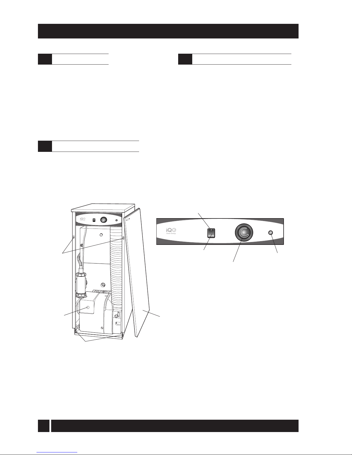
To gain acces to the controls, pull the front
panel forward at the top to disengage the
fixing clips then lift it up and off the boiler.
To replace locate the bottom of the panel
over the fixing tags then push it towards the
boiler to engage the fixing clips.
Fig. A Boiler controls
1 Ensure that - There is sufficient fuel, of the correct
type, in the supply tank and all fuel supply valves
are open. The
water supply is on. The electricity
supply to the boiler is off. The boiler On/Off switch
is set to OFF. The room thermostat (if fitted) is at
the desired setting. The boiler thermostat is set to
the required setting (see Section 2.7).
2 Switch on the electricity supply to the boiler.
3 Set the On/Off switch to ON and, if fitted, the
pro
gr
ammer (CH or HW) to ON.
The boi
ler will now light automatically.
4 If you have a programmer fitted in your system,
refer to the instructions supplied with the
programmer and set the programmer. Set the H
W
and CH functions to TIMED. The boiler will now
operate during the 'on' periods set on the
programmer.
Boiler
thermostat
Overheat
thermostat
reset button
(under cover)
On/Off
switch
OVERHEAT
RESET
HEATING
TEMPERATURE
OVERHEAT
RESET
BOILER
OFF
ON
HEATING
TEMPERATURE
ON
BOILER
OFF
Lock-out
button
Front panel removed
(pull forward at top, then
lift off)
Front panel
fixing clips
Front panel bottom locating tags
GRANT
Mains On
neon
iQE Horizon Internal Oil Boiler
2.1
About your boiler
2.3
Lighting your boiler (see Fig. A)
2.2
Boiler controls (see Fig. A)
5
For short periods - Set the On/Off to OFF. To
restart, simply set the switch to ON.
For long periods: Set the On/Off switch to OFF
and switch off the electricity supply to the boiler.
If required, the fuel supply valve may be closed
and the water and electricity supplies turned off
at the mains.
To restart, refer to the full lighting instructions
given in Section 2.3.
1 Check that the
boiler On/Off switch is ON.
2 Check that the programmer (if fitted) is working
and is in an 'on' period.
3 Check that all thermostats are set to the desired
setting and are calling for heat.
4 Check if the burner 'Lock-out' reset button
(on the burner) is lit. If it is, press it to start the
burner. If the burner fails to light and goes to
'Lock-out' again, check that you have sufficient
fuel in the storage tank and that the fuel supply
valve is open. Check that the fire valve in the oil
supply line has not tripped
5 Ensure that a fuse has not blown or that the
electricity supply has not failed.
6 Check to see if the safety thermostat has operated
(see Section 2.7).
If the burner still fails to light after carrying out these
checks then a fault exists. Switch off the electricity
supply to the boiler and contact your Service
engineer.
iQE Horizon Internal oil boilers only operate on
Class C2 Kerosene to BS 2869:1998.
You should always quote this type of fuel when
ordering from your supplier.
Do not wait until the fuel runs out before you order
some more. Sludge in the bottom of the tank may be
drawn into the fuel lines. If it is possible, switch off
the boiler when the new supply is delivered and
leave the fuel to settle for an hour before restarting
the boiler.
2 - USER INSTRUCTIONS
1 Boiler thermostat - This control allows the
temperature of the water leaving the boiler to heat
the radiators and domestic hot water to be adjusted.
Note: If you have a cylinder thermostat on
your hot water cylinder, this will control the
temperature of your domestic hot water. The
boiler thermostat setting must be equal to or
above the cylinder thermostat setting to
enable the cylinder thermostat to control the
domestic hot water system.
2 Burner Lock-out reset button - If there is a
burner malfunction, a built-in safety circuit
switches the burner off and the 'Lock-out' reset
button (on the burner) will light. Usually such
malfunctions are short lived and pressing the
reset button will restore normal operation.
If the burner continually goes to 'Lock-out'
a fault exists or the fuel supply is low. If you
have sufficient fuel, you will need to call
your Service engineer.
3 Safety thermostat - Your boiler is fitted with a safety
heat thermostat which will automatically switch off
the boiler in the case of a control malfunction
causing overheating.
If your boiler goes off and you try to light it but
nothing happens and the 'Lock-out' reset
button on the burner is not lit, the overheat
thermostat has probably operated. The boiler
will not light until the thermostat is reset. To
reset, unscrew the small plastic cap (see
Fig.A), press the button then replace the cap. If
this condition continually repeats, contact your
Service engineer.
4 Programmer (if fitted) - Refer to the instructions
suppplied with the Programmer.
5 Ventilation - Always ensure that the boiler has
adequate ventilation. Any ventilation openings
provided by the Installer must not be obstructed.
Periodically check that they are clear.
Do not attempt to 'box in' the boiler or build
a compartment around it before consulting
your Installer.
Do not place any combustible material
around or on the boiler or flue pipe.
6 Flue terminal - The flue terminal on the outside wall
must not be o
bstructed or damaged.
In severe conditions check that the terminal
does not be
come blocked by snow.
iQE Horizon Internal Oil Boiler
2.7
General notes and care of your system
2.4
Turning off your boiler (see Fig. A)
2.5
Points to check if burner fails to light
2.6
About your fuel
6
7 Frost protection - Your Installer may have fitted
a f
rost thermostat. If not, and you are likely to
be away for a short time, leave the boiler on
with the boiler thermostat set at a low setting.
For longer periods the boiler and system
should be drained. Contact your Service
engineer for draining and filling the system.
8 Cleaning and servicing - Lightly wipe over the
case with a damp cloth and a little deterg
ent.
Do not use abrasive pads or cleaners.
You must have your boiler serviced at least
once a year to ensure safe and efficient
operation. Contact your Service engineer for
further details.
9 Failure of electricity supply - If the electricity
sup
ply fails, the boiler will not operate. It should
re
light automatically when the supply is restored.
If
a programmer is fitted it will retain the time
settings for up to 24 hours and will not have
to be reset to the correct time of day when
the supply is restored (the display remains for
up to 1 hour, but will re-appear when the
supply is restored).
The boiler requires a 230/240 V ~ 50 Hz
supply. It must be protected by a 5 Amp fuse.
Warning: This appliance must be earthed.
If your boiler is operating on a sealed heating
system, the installer will have pressurised the
system and should have told you (or set it on the
pressure gauge) the system pressure when cold
(this is normally between 0.5 and 1.0 bar, which
will increase slightly when hot). If the pressure
(when cold) is below the set pressure mentioned
above, you can re-pressurise the system. If the
system requires frequent re-pressurising, ask your
Installer or Service engineer to check the heating
system for leaks and to check the expansion
vessel air charge.
The boiler or system will be fitted with an
automatic air vent to remove air from the system.
Any air trapped in the radiators should be
removed by venting the radiators using the vent
screw at the top of each radiator. Only vent a
radiator if the top is cool and the bottom is
hot. Excessive venting will reduce the system
pressure, so only vent when necessary and check
the system pressure as mentioned above. Repressurise the system if necessary.
2 - USER INSTRUCTIONS
Th
e boiler or system may be fitted with a safety
valve to release excess pressure from the system.
If water or steam is emitted from the end of the
safety valve discharge pipe, switch off the boiler
and contact your Installer or Service engineer.
Th
e expansion vessel air charge must be checked
annually. Failure to maintain an adequate air
charge in the vessel may invalidate the warranty.
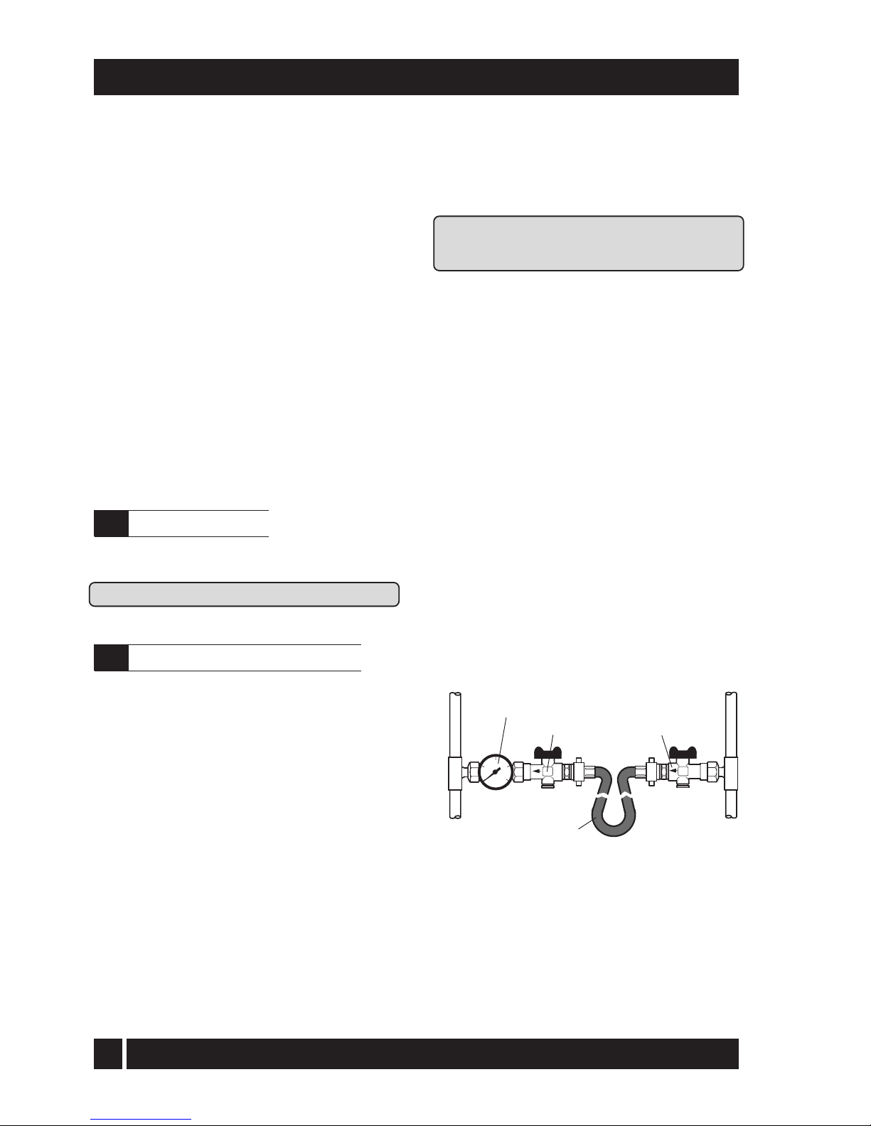
To re-pressurise the system by adding water:
1 Only add water to the system when it is cold and
the boiler is off. Do not overfill.
2 Ensure the flexible filling loop (see Fig. B) is
con
nected and that the shut off valve connecting
it to the boiler is open and the double check
valve at the front is closed. A valve is open when
th
e operating lever is in line with the valve, and
close
d when it is at right angles to it.
3 Gradually open the double check valve on the front
of the filling loop until water is heard to flow.
W
hen the black needle of the pressure gauge is
between 0.5 and 1 bar, close the valve.
4 Vent each radiator in turn, starting with the lowest
one in the system, to remove air.
5 Continue to fill the system until the pressure gauge
indicates between 0.5 and 1.0 bar. Close the fill
point
valve.
6 Repeat steps 4 and 5 as required.
7 Close the valves either side of the filling loop and
disconnect the loop.
Sealed system filling loop arrangement - Fig. B
Central
heating
system
Mains
water
supply
Pressure gauge
Double check valve
Shut off valve
Flexible filling hose
iQE Horizon Internal Oil Boiler
2.8
Electricity supply
2.9
Sealed central heating system
7
25.6
87350
22 mm
22 mm
1 780
1 100
22 mm (only connect
plastic pipe) 100 mm
28.5 mbar
10 mbar
28 m
1m
65 to 75° C
111° C ± 3° C
Less than 50° C
230/240 V ~ 50 Hz Fused at 5 Amp
90
4.2
0.85
¼" BSP Male (on end of flexible fuel
hose) Minimum flue draught - 8.7 N/m²
(0.035 in wg) Maximum flue draught -
37 N/m² (0.15 in wg) 2.5 bar
2.5 bar
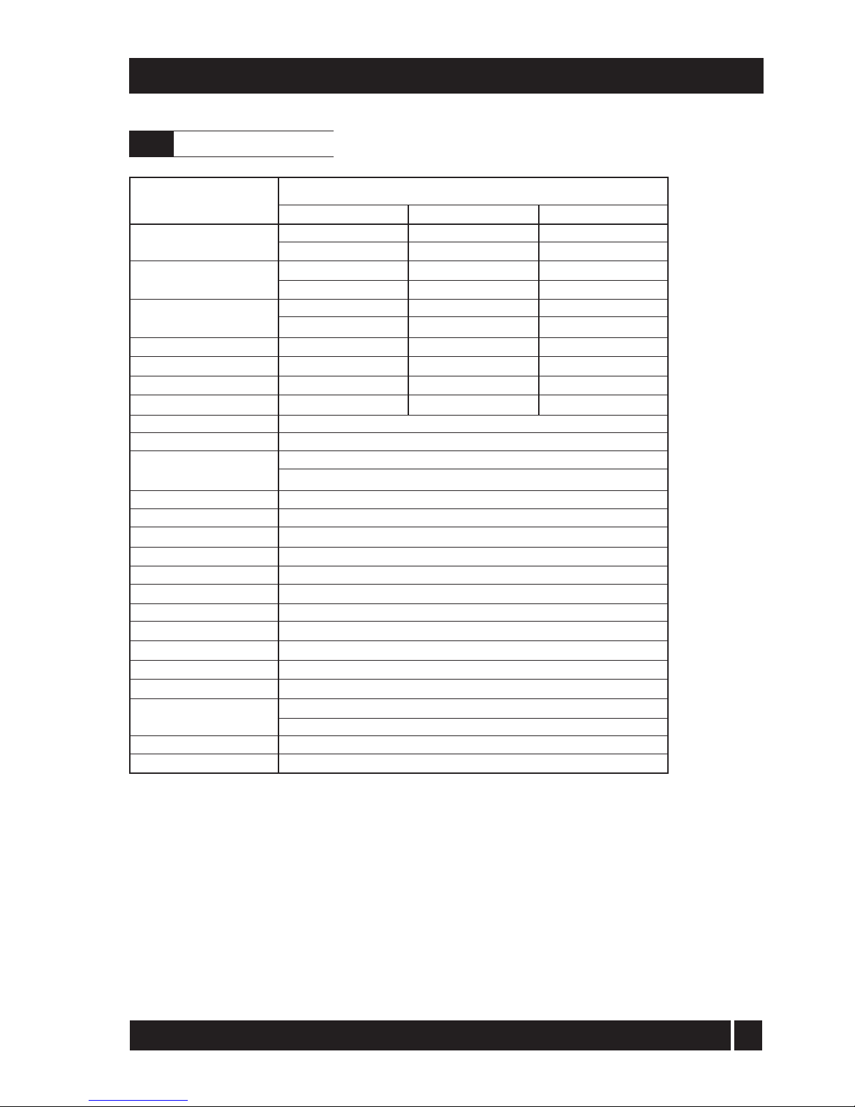
3- BOILER TECHNICAL INFORMATION
Model
Water content litre
gal
* Weight (dry) kg
lb
Max. heat output kW
(kerosene) Btu/h
Flow connection
Return connection
Min. flow rate (ΔT=10°C) l/h
Min. flow rate (ΔT=20°C) l/h
Condensate connection
Flue diameter (conventional)
Waterside resistance
Flow/Return temp. diff. of 10°C
Flow/Return temp. diff. of 20°C
Maximum static head
Minimum circulating head
Boiler thermostat range
Limit (safety) stat shut off temp
Max. hearth temperature
Electricity supply
Motor power Watts
Amps
Amps
Starting current
Running current
Oil connection
Conventional
flue
Max operating press - sealed sys
Max operating press - open sys
* Weight includes burner but excludes flue.
iQE Horizon
Internal 15/26
13
2.9
103
227
26/35
19
4.2
121
267
34.7
118400
22 mm
22 mm
2 980
1 490
iQE Horizon Internal Oil Boiler
3.1
Boiler technical data
8
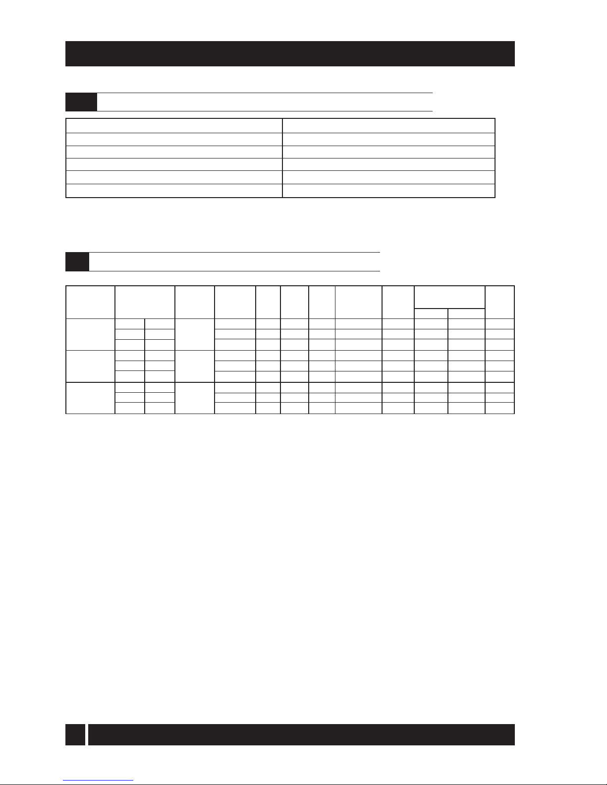
3 - BOILER TECHNICAL INFORMATION
Note: iQE boilers are only for use with kerosene.
(kW)
15.1
18.1
20.7
22.7
25.6
25.6
30.8
34.7
(
Btu/h)
51 500
61 750
70 600
77 500
87 350
87 350
105 100
118 400
Model and Heat Output
Nozzle
0.50/80°EH
0.55/80°EH
0.60/80°EH
0.65/80°EH
0.75/80°EH
0.75/80°EH
0.85/80°EH
1.00/80°EH
Oil
press.
(bar)
7.5
7.5
8.5
8.5
8.0
8.0
9.1
8.0
Smoke
No.
0 - 1
0 - 1
0 - 1
0 - 1
0 - 1
0 - 1
0 - 1
0 - 1
Fuel flow
rate
(kg/h)
1.29
1.53
1.78
1.95
2.19
2.19
2.65
2.93
Flue
70 - 75
75 - 80
85 - 90
85 - 90
90 - 95
75 - 80
85 - 90
90 - 95
CO
2
(%)
11 - 12
11 - 12
11 - 12
11 - 12
11 - 12
11 - 12
11 - 12
11 - 12
15/26
Riello RDB2.2
15/26
Riello RDB2.2
26/35
Riello RDB2.2
burner type
Heating system pressure (cold)
Operating pressure of pressure relief valve
Expansion vessel size
Max heating system volume (including boiler)*
Cold water mains connection (for filling loop)
Pressure relief valve discharge connection
Maximum 1.0 bar, Minimum 0.5 bar
2.5 bar
12 litres (pre-charged at 1 bar)
128 litres (approximately)
15 mm compression (provided)
15 mm compression (provided)
* Based on vessel charge and system cold fill pressure of 0.5 bar
SEDBUK
efficiency
(%)
93.0
92.4
92.1
Disc setting B
Disc setting C
Fixed
Fixed
Fixed
Fixed
Fixed
Fixed
Burner
head/disc
setting
*
*
Notes:
1 The data given above is approximate only and based on the boiler using a low level flue.
2 The above settings may have to be adjusted on site for the correct operation of the burner.
3 Gas Oil is not suitable for use with the iQE boiler range.
4 The net flue gas temperatures given above are ± 10%.
5 When commissioning the air damper must be adjusted to obtain the correct CO2 level.
6 *
F
actory settings: 15/21 - 18.1 kW, 21/26 - 22.7 kW, 26/35 - 30.8 kW.
7 The combustion door test point may be used for CO2 and smoke readings only. Do not use this test point for
temperature o
r efficiency readings.
8
9
W
hen setting the 15/26 to 15.1 kW output a burner air adjuster disc requires positioning. Refer to Section 7
Commissioning.When setting the 26/35 to 25.6 kW output the combustion head must be changed.
Refer to Section 9.4 Cleaning the burner.
The installer must amend the boiler data label if the output is changed.
Flue gas analysis
To allow the boiler to be commissioned and serviced, the boiler is supplied with a combustion test point on the front
cleaning door. When this test point is used please note the following:
1. The test point is for CO2 and smoke readings only.
2. The boiler efficiency and temperature must be taken from the flue test point on high level and vertical flue adaptors.
3. Low level flues do not contain a test point. The temperature and efficiency readings must be taken from the flue terminal.
Burner
head
type
T1
T1
T1
T2
T2
T2
T3
T3
Flue gas temp °C
Door
155 - 160
175 - 180
195 - 200
205 - 210
215 - 220
190 - 195
215 - 220
220 - 225
Danfoss
iQE Horizon Internal Oil Boiler
3.2
Sealed system data - iQE Horizon models with sealed system kit
3.3
iQE Horizon Internal oil boilers using Class C2 kerosene

9
3 - BOILER TECHNICAL INFORMATION
Fig. 1b - 26/35 dimensions
Fig. 1a - 15/26 dimensions
61
82
170
61
86
LEFT SIDE VIEW
587
19
115
60
25
Flue centre line
RIGHT SIDE VIEW
PLAN VIEW
470
603
150
FRONT VIEW
470
441
250
900
696
205
Flue
spigot
Alternative
condensate
drain outlets
624
17
REAR VIEW
430
200115
125
860
705
RIGHT SIDE VIEW
200
28
125
813
712
17
LEFT SIDE VIEW
110
605
Flue centre line
Flue centre
line
Alternative
condensate
drain outlets
177
88
445
PLAN VIEW
430
605
110
iQE Horizon Internal Oil Boiler
3.4
Boiler dimensions

10
4 - GENERAL BOILER INFORMATION
iQE G-system ...... Standard external high level/
vertical flue starter kit (room sealed) components available:
Ex
te
rnal high level/vertical flue starter kit
short (room sealed)
Extensions 150 mm, 250 mm, 450 mm, 950
mm, adjustable 195 to 270 mm and 45° elbow
High level terminal
Vertical terminal
iQE W-system ...... High level and vertical concentric
balanced flue kit - components available:
Extensions 225 mm, 450 mm, 950 mm,
adjustable 275 to 450 mm and 45° elbow
Vertical concentric balanced flue kit
Extensions 225 mm, 450 mm, 950 mm,
adjustable 275 to 450 mm and 45° elbow
iQE R-system (15/26 only) ..... A flexible
vertical balanced flue system designed to be
fitted inside an existing masonry chimney.
Flue extensions and 45° elbows from the
iQE W- system may be used to extend the
flue system between the boiler and the
flexible section of the system.
A
ll burners are pre-se
t for use with kerosene and
are supplied ready to connect to a single pipe fuel
supply sys
tem with a loose flexible fuel line and male
adaptor supplied with the boiler.
If required, an additional flexible fuel line
(600mm) and BSP male adaptor (1/4" x 3/8")are
available to purchase from iQE.
The temperature of the water leaving the boiler
to heat the radiators and hot water cylinder is
User adjustable.
The boiler is fitted with an overheat thermostat
(which allows it to be used on a sealed central heating
system) which will automatically switch off the boiler
if the heat exchanger exceeds a pre-set temperature
of 111° C ± 3° C.
The control panel is fitted with an ON/OFF
switch, boiler thermostat control knob and the
manual reset button for the overheat
thermostat.
4.2
Boiler components
The
iQE Horizon Internal range of automatic
pressure jet oil boilers have been designed for use
with a fully pumped central heating system with
indirect domestic hot water cylinder. They are not
suitable for use with either a direct cylinder or a
'primatic' cylinder or gravity hot water.
The boilers are suitable for use on open vented or
sealed central heating systems. System models are
supplied with the necessary components factory
fitted. See Section 4.13.
All models are supplied with the control panel and
burner factory fitted.
The boilers can be connected to either a conventional
flue system or a balanced flue system, as required.
For Conventional flue applications where a
chimney is to be lined - iQE recommends the use
of the O-system, specifically designed for the
Internal range of iQE Horizon oil boilers. Refer to
Section 4.7 for further details.
Where a rigid conventional flue - either internal or
external - is required, iQE recommends the use of
the G and O flue system components. As no flue
adaptor is supplied with the boiler it will be
necessary to purchase the iQE Horizon adaptor
kit in order to correctly connect the G and O
system flue components to the boiler.
Flue adaptor kit - Ref. iQE CF15/35 - is used for all
iQE models from 15 to 35 kW as they all can use the
100 mm G and O system components to
construct a flue of maximum vertical height 8
metres.
Important: The flue system materials and
construction MUST be suitable for use with oilfired condensing boilers. Failure to fit a suitable
conventional flue may invalidate the warranty on
the boiler.
Fitting instructions for the Low level concentric, High
level and Vertical balanced flue kits are supplied
with the kits. Where a balanced flue system is
required, the following flue kits are available
from iQE,
Refer to Section 4.8 for further details.
iQE Y-system ..... Standard low level concentric
balanced flue - components available:
Low le
vel concentric balanced flue short
Extensions 225 mm, 450 mm and 675 mm
90° extension elbow
45° extension elbow
45° elbow
iQE Horizon Internal Oil Boiler
4.1
Boiler description

11
The installation should also be in accordance with
the latest edition of the following British Standard
Codes of Practice:-
BS 715 Metal flue pipes, fittings, terminals
and accessories.
BS 799:5
Oil storage tanks.
BS 1181
Clay flue linings and flue terminals.
BS 4543:3 Factory made insulated chimneys for
oil fire
d appliances.
BS 4876
Performance requirements for oil
burning appliances.
BS 5410:1 Code
of Practice for oil firing appliances.
BS 5449
BS 7593
Forced circulation hot water systems.
Code of Practice for treatment of
BS 76
71
water in heating systems.
Requirements for electrical installations,
IEE Wiring Regulations.
Failure to install and co
mmission appliances
correctly
may invalidate the boiler warranty.
IMPORTANT
Before starting any work on the boiler, or fuel
supply please read the health and safety
information given in Section 14 on page 47.
4.4.1 Fuel storage
The tank should be positioned in accordance
with the recommendations given in BS 5410:1:1997,
which gives details of filling, maintenance and
protection from fire.
A
steel tank may be used and must be constructed
to
BS 799:5:1987 and OFS T200.
A galvanised tank must not be used.
A plastic tank may be used and must comply
with OFS T100.
Note: Plastic tanks should be adequately and
uniformly supported on a smooth level surface,
across their entire base area.
Inst
allation of a iQE Horizon Internal boiler must
be in accordance with the following
recommendations:-
a Building
Regulations for England and Wales,
an
d the Building Standards for Scotland
issued by the Department of the Environment
and any local Byelaws etc.
b Model and local Water Undertaking Byelaws.
c A
pplicable Control of Pollution Regulations.
d T
he following OFTEC requirements:-
OFST 100 Polythene
oil storage tanks for
d
istillate fuels.
OFST 200
Fuel oil storage tanks and tank
bunds for use with distillate
fuels,lubrication oils and waste
oils.
4
- GENERAL BOILER INFORMATION
Regional statutory requirements may deem this appliance to be a 'controlled service'.
Where this is the case, it is a legal requirement that the appliance is installed and
commissioned either under the remit of building control or by a 'Competent person' such
as a suitably qualified Oftec registered technician.
Fig. 2 - Components
OVERHEAT
RESET
HEATING
TEMPERATURE
ON
BOILER
OFF
Lock-out
button
Front panel
removed
(pull forward
at top, then
lift off)
Front panel
fixing clips
Condensate
trap
Front panel bottom locating tags
GRANT
Air supply
tube
Burner
iQE Horizon Internal Oil Boiler
Further information may be obtained from the
OFTEC Technical Information Book 3
(Installation requirements for oil fired boilers and
o
il storage tanks).
4.4
Fuel supply
4.3
Regulations to comply with
12
4 - GENERAL BOILER INFORMATION
4.4.2 Fuel pipes
1 Fuel supply pipes should be of copper tubing
with an external diameter of at least 10 mm.
Gal
vanised pipe must not be used.
All pipe connections should preferably use flared
fittings. Soldered connections must not be used
on oil pipes.
2 Flexible pipes must not be used outside the boiler case.
3 A remote sensing fire valve must be installed in
the fuel supply line (outside) where it enters the
bu
ilding, with the sensing head located above
the burner. Recommendations are given in BS
5410:1:1997.
4 A metal bowl type filter with a replaceable micronic
filter must be fitted in the fuel supply line adjacent
to the boiler.
A shut-off valve should be fitted
before the filter, to allow the filter to be serviced.
5 A flexible fuel hose, adaptor and 1/4" BSP isolation
valve are supplied loose with the boiler for the
final connection to the burner. If a two pipe
system or 'Tiger Loop' type de-aerator is used,
an additional flexible fuel hose (600 mm) and
male adaptor are available to purchase from
iQE.
6 Metal braided flexible hoses should be replaced
annually when the boiler is serviced. Long life
flex
ible pipes should be inspected annually
and replaced at least every 60 months.
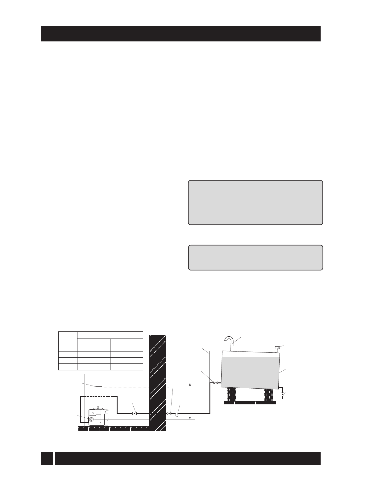
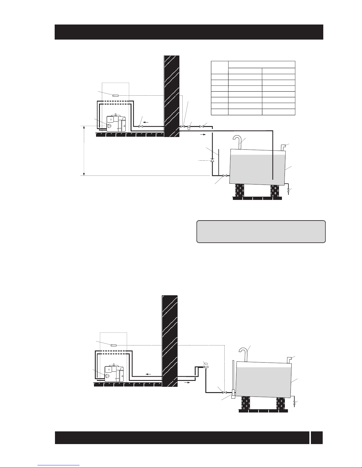
4.4.3 Single pipe system - (See Fig. 3)
1 Where the storage tank outlet is above the burner
the single pipe system should be used. The
height of the tank
above the burner limits the
length of pipe run from the tank to the burner.
2 As supplied the burner is suitable for a single pipe system.
4.4.4 Two pipe system - (See Fig. 4)
1 When the storage tank outlet is below the burner,
the two pipe system should be used. The pipe
runs should be as shown in Fig. 4. The return
p
ipe should be at the same level in the tank as
the supply pipe, both being 75 to 100 mm
above the base of the tank. The pipe ends
should be a sufficient distance apart so as to
prevent any sediment disturbed by the return
entering the supply pipe.
2 Avoid the bottom of the tank being more than 3 m
below the burner.
3 A non-return valve should be fitted in the supply
pip
e together with the filter and fire valve. A
non-return valve should be fitted in the return
pipe if the top of the tank is above the burner.
4 T
o be used with a two-pipe system,
the burner must be fitted with an additional
flexible fuel hose and a male adaptor. They are
available to purchase from iQE. Part No.
iQELINE / iQE3814
5 The pump vacuum should not exceed 0.4 bar.
Beyond
this limit gas is released from the oil.
For guidance on installation of top outlet fuel
tanks and suction oil supply sizing, see OFTEC
booklet T1/139. Available at www.oftec.org.uk.
Fig. 3 - Single pipe system
Filter
Fire
valve
Shut-off
valve
Shut-off
valve
A
Sludge
valve
Fill
pipe
Vent
pipe
Level
gauge
Fuel
storage
tank
Fire
valve
sensor
Pump
Head A
(m)
Maximum pipe run (m)
0.5
1.0
1.5
2.0
10mm OD pipe
10
20
40
60
12mm OD pipe
20
40
80
100
iQE Horizon Internal Oil Boiler
13
Fig. 5 - De-aeration device system
4.4.5 Tiger Loop system - (See Figs. 5 and 6)
1 When The storage tank is below the burner, an alternative
to a two pipe syste
m can be achieved using a 'Tiger
Loop' type oil de-aerator (iQEDEAER). This
effectively removes the air from the oil supply on a
single pipe lift.
2 The de-aerator is connected close to the boiler as a
two pipe system (omitting the non-return valve) as
shown in Fig. 5. Refer to the manufacturers
instructions supplied with the de-aerator.
The de-aerator must be mounted vertically.
4 - GENERAL BOILER INFORMATION
Fig. 4 - Two pipe system
Note: To prevent any possibility of fuel fumes
entering the building, the de-aerator must be
fitted outside.
3 To be used with a de-aerator, the burner must be
fitted with an additional flexible fuel hose (a
f
lexible fuel hose (600 mm) and 3/8" to 1/4"
BSP male adaptor are available to purchase
from iQE.
Filter
Fire
valve
Shut-off
valve
Shut-off valve
Shut-off
valve
See
section 4.4.6
A
Return
Supply
Head A
(m)
Maximum pipe run (m)
0
0.5
1.0
1.5
2.0
3.0
3.5
10mm OD pipe
35
30
25
20
15
8
6
12mm OD pipe
100
100
100
90
70
30
20
Non
return
valve
Fire
valve
sensor
Sludge
valve
Fill
pipe
Vent
pipe
Level
gauge
Fuel
storage
tank
Fire
valve
Tankmaster
See
section 4.4.6
Sludge
valve
Fill
pipe
Vent
pipe
Fuel
storage
tank
De-aeration
device e.g. Tiger
Loop See Fig. 6
Fire
valve
sensor
Return
Supply
iQE Horizon Internal Oil Boiler
14
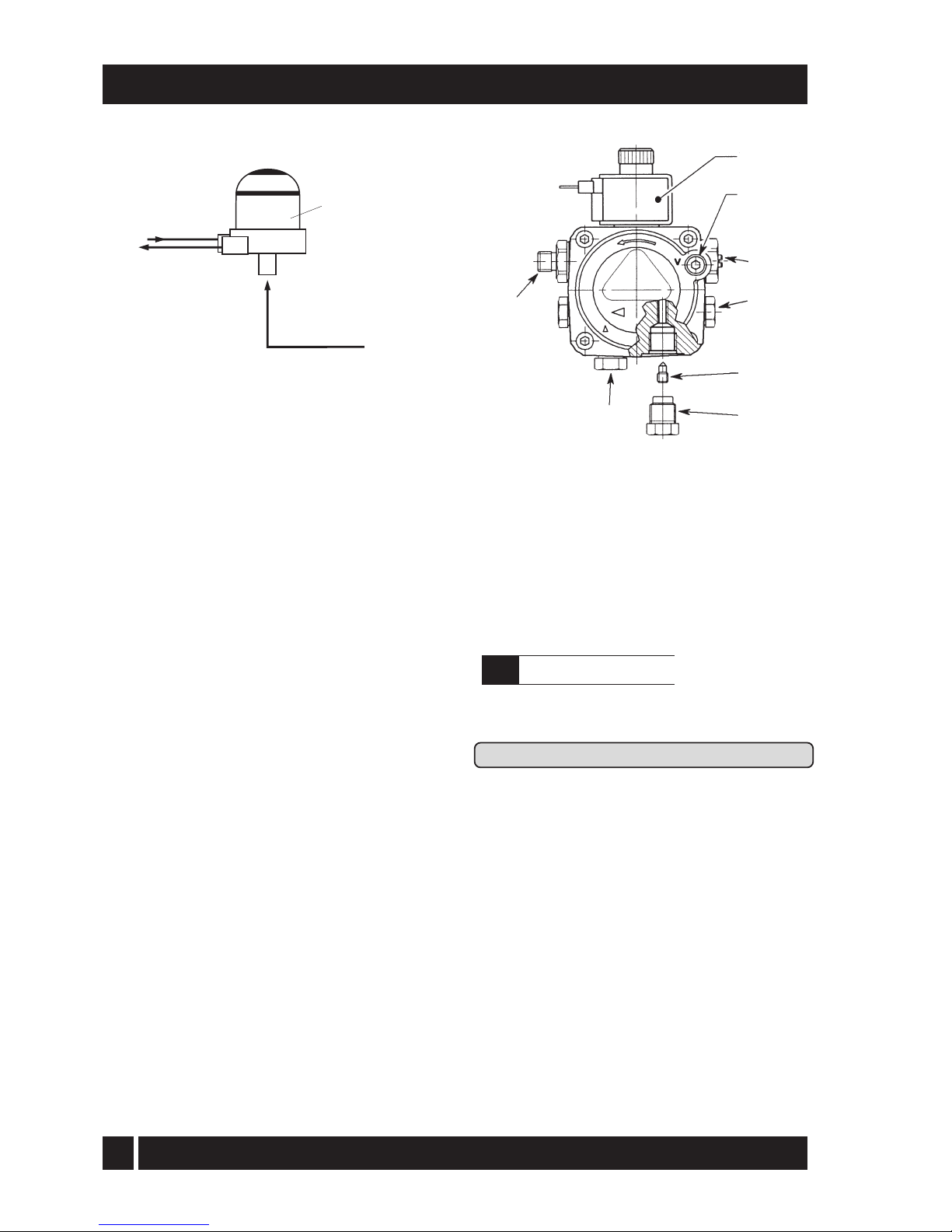
4.4.6 Two pipe oil supplies
Riello RDB burner - See Fig. 7
1 The fuel pump is supplied for use with a single
pip
e fuel supply system. For use on a two pipe
system, it is necessary to fit the By-pass screw
(see Fig. 7) into the tapping in the return port.
2 The By-pass screw is supplied in the boiler
accessory pack.
3 Remove the plastic burner cover (secured by
two screws). To gain access, it may be
necessary to remove the plinth - loosen the
screw securing
the right hand side of the plinth,
then withdraw the plinth forward from the right
and away from the case.
4 Remove and discard the blanking plug from the
return connection of the pump and fit the
By-pass screw using an hexagonal key.
5 Connect the return oil flexible fuel hose to the pump.
6
C
onnect the male adaptor to the flexible fuel hose
Fig. 6 - Tiger loop 'de-aeration' device
4 - GENERAL BOILER INFORMATION
Fig. 7 - Riello RDB pump
1 Oil inlet connection
2 Re
turn connection
3 By-pass screw
4 Pres
sure gauge connection
5 Pressure adjuster
6 Vacuum gauge connection
7 Solenoid
8 Supply to nozzle
4.5
Electricity supply
1 A 230/240 V ~ 50 Hz mains supply is required.
Refer to Section 10 for connection details.
Th
e boiler must be earthed.
2 The supply must be fused at 5 Amp and there must
only be one common isolator for the boiler
and control system, providing complete
electrical isolation.
3 A fused double pole switch or a fused three pin
plug and shuttered outlet socket should be
used for the connection.
4 The power supply cable should be at least 0.75 mm²
PVC as specified in BS 6500, Table 16.
5 All the wiring and supplementary earth bonding
external to the boiler must be in accordance
with the current I.E.E. Wiring Regulations.
6 Any room thermostat or frost thermostat used must
be suitable for use on mains voltage.
7 In the event of an electrical fault after installation
of the boiler, the following electrical system
checks must be carried out:- Short circuit,
Polarity, Earth continuity and Resistance to
earth.
1/4" BSP
female
connections
Tiger Loop
SUPPLY
TO PUMP
RETURN
FROM PUMP
SUPPLY
FROM TANK
1
2
3
4
5
6
7
8
iQE Horizon Internal Oil Boiler
15
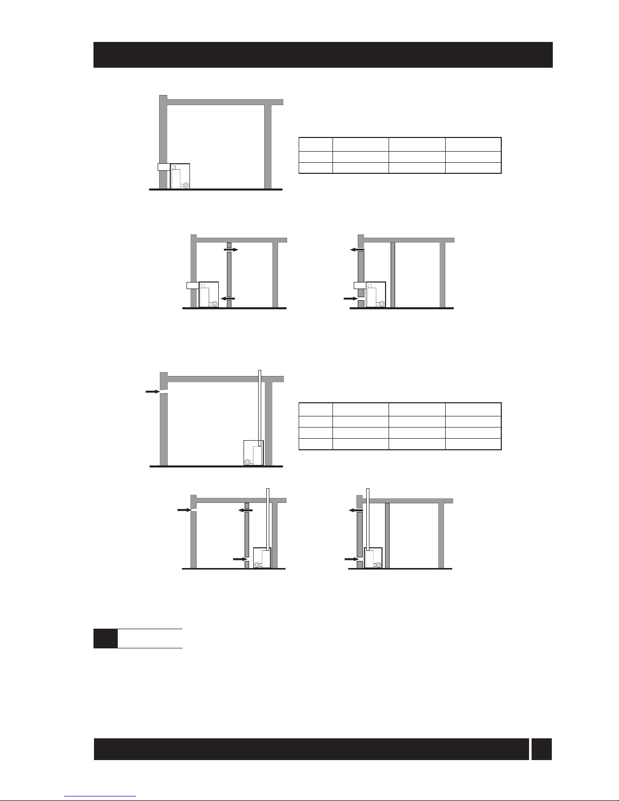
BOILER IN
ROOM
Conventional open flue
C
BOILER IN
COMPARTMENT
Conventional open flue
compartment ventilated from room
Conventional open flue
compartment ventilated from outside
C
C
D
D
E
BOILER IN
ROOM
Room sealed balanced flue no
ventilation required to room
BOILER IN
COMPARTMENT
Room sealed balanced flue
compartment ventilated from room
Room sealed balanced flue
compartment ventilated from outside
B
B
A
A
Fig. 8 - Air supply for room sealed balanced flue boilers
4 - GENERAL BOILER INFORMATION
Fig. 9 - Air supply for conventional flue boilers
15/21 kW
116 cm² (18 in²)
232 cm² (36 in²)
26/35 kW
198 cm² (31 in²)
396 cm² (62 in²)
Output
Vent A
Vent B
15/21 kW
116 cm² (18 in²)
232 cm² (36 in²)
348 cm² (54 in²)
26/35 kW
198 cm² (31 in²)
396 cm² (62 in²)
594 cm² (93 in²)
Output
Vent C
Vent D
Vent E
See Figs. 8 and 9
A sufficient permanent air supply to the
boiler should be provided:
a For proper combustion of fuel and
effective discharge of combustion
products to the open air.
b For the ventilation of any confined space in
which the boiler is installed to prevent
overheating of the boiler any
equipment in and near the boiler.
21/26 kW
143 cm² (23 in²)
286 cm² (46 in²)
429 cm² (69 in²)
21/26 kW
143 cm² (23 in²)
286 cm² (46 in²)
iQE Horizon Internal Oil Boiler
4.6
Air supply
 Loading...