

Page 1
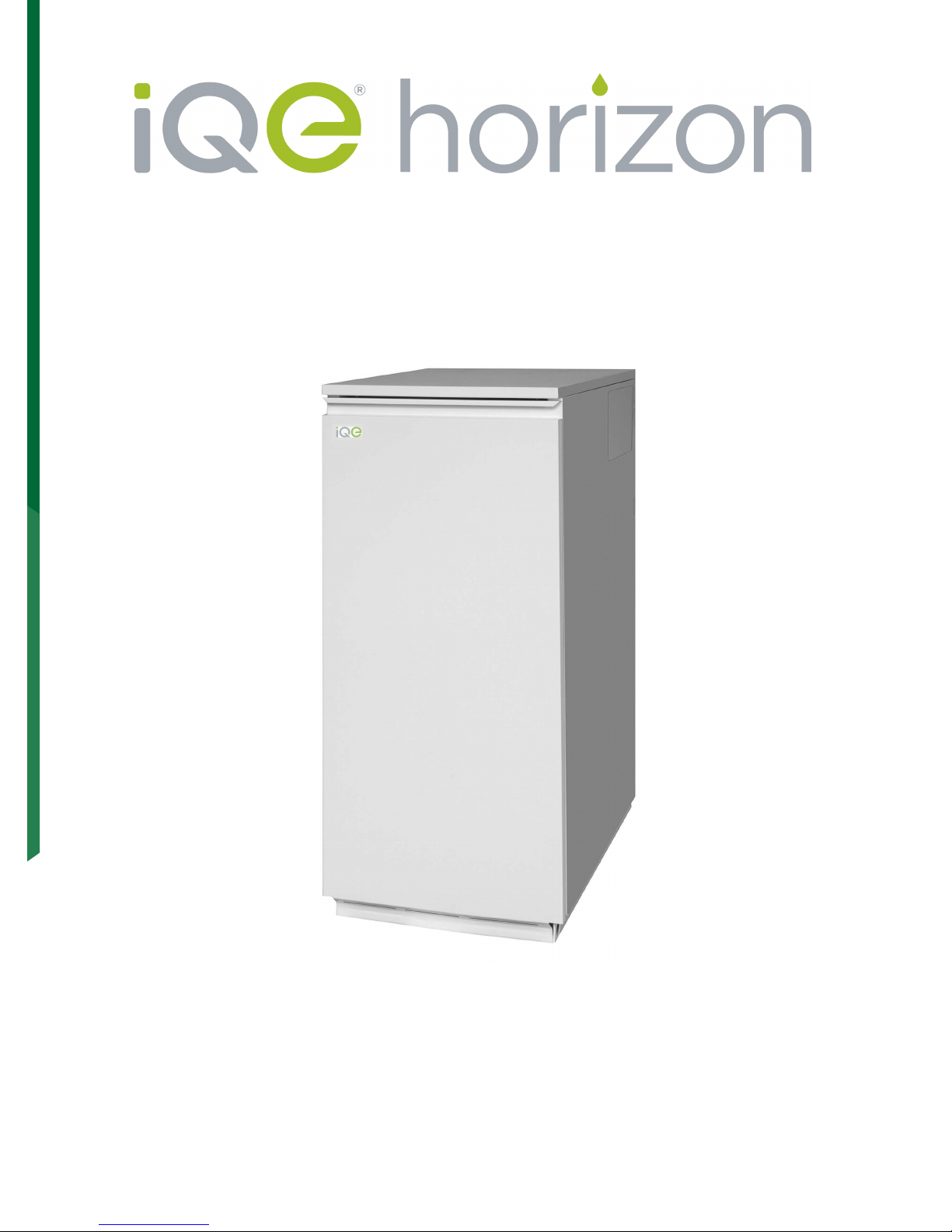
Installation, Servicing & User Instructions
Oil Fired Condensing Boiler 15/26 Internal and 26/35 Internal
iQE Doc Hor15-35 01 V1.3 October 2013
Page 2
Dear iQE Owner
Thank you for choosing an iQE boiler for your home heating. iQE is committed to
supplying quality products with a first class after sales service to all of our customers.
OUR SERVICE TO YOU
Your boiler is designed to give years of heating comfort. However any appliance, no matter
how well manufactured, can require repairs at some stage. For your peace of mind iQE have
continued investment and development to ensure it provides a dedicated nationwide team
of qualified engineers and a Customer Services Helpline.
BOILER REGISTRATION
For your safety, iQE requires that the boiler is installed by an appropriately qualified engineer
and the work registered with OFTEC Register within 30 days of completion*.
You will then receive notification to prove that this has been done. Your installer is also
required to complete the OFTEC CD10 in the Installation Guide provided with the appliance.
The installation also requires the completion of the CD11 (not supplied) at the time of
commissioning.
In order to maintain the warranty and to help ensure your boiler runs safely
and efficiently, it is required that your boiler is serviced annually.
Please refer to the terms and conditions for further clarification.
Andy Rudd
Commercial Director
*
I t is a legal requirement that an installation or change of a heating appliance is notified to the relevant
Local Authority, this requirement is met by the notification to the OFTEC Register or equivilant.
Page 3

2
iQE Horizon Internal Oil Boiler
Subject PageSection
1 Introduction ............................................ 3
2
User instructions .................................. 4
3 Boiler technical information ........... 7
4
Gen
eral boiler information..................11
5 Con
densate disposal .......................... 27
6 Boiler installation
.................................. 31
7
Commissioning....................................... 37
8
Information for th
e user ....................38
9
Boiler servicing ..................................... 38
10
Wiring diagrams ...
................................ 42
11
Fault finding .......................................
......43
12
Boiler spares
.......................................... 45
13
Bu
rner spares ........................................ 46
14
Heal
th and safety information ....... 47
15
EC declaration of conformity
........ 48
Date: ..............................
Commissioning engineer: .............................................................................. Tel. No: ....................................
Boiler model/output: ........................................ kW Fu
el type: Kerosene
Nozzle size: .................................... Pump pressure: .................... Air setting: ...........................
Flue gas % CO2: ............................. Net flue gas temp:................ Smoke No:...........................
LIST OF CONTENTS
Warranty.....................................................49
SERVICE LOG
It is recommended that the boiler should be regularly serviced, at least once a year,
and the details recorded.
16
COMMISSIONING REPORT
Page 4

3
During the combustion process, hydrogen and
oxygen combine to produce heat and water
vapour. The water vapour produced is in the form
of superheated steam in the heat exchanger. This
superheated steam contains sensible heat
(available heat) and latent heat (heat locked up in
the flue gas). A conventional boiler cannot
recover any of the latent heat and this energy is
lost to the atmosphere through the flue.
The iQE condensing boiler contains an extra
heat exchanger which is designed to recover the
latent heat normally lost by a conventional
boiler. It does this by cooling the flue gases to
below 90° C, thus extracting more sensible heat
and some of the latent heat. This is achieved by
cooling the flue gases to their dew point
(approximately 55° C).
To ensure maximum efficiency, the boiler
return temperature should be 55° C or less,
this will enable the latent heat to be
condensed out of the flue gases. The boiler will
achieve nett thermal efficiencies of
100%.
To achieve maximum performance from the iQE
Internal boiler, it is recommended that the
heating system is designed so that a
temperature differential of 20° C between the
flow and return is maintained. The use of
modulating circulating pumps (now widely
available) and effective control systems should
be considered.
Th
e iQE Internal boiler will however still operate
at extremely high efficiencies even when
it is not
in condensing mode and therefore is suitable for
fitting to an existing heating system without
alteration to the radiator sizes. The boiler is
capable of a maximum flow temperature of 75° C.
To achieve the maximum efficiencies possible
from the iQE boiler, the heating system should
be designed to the following parameters:
Radiators:-
Flow temperature 70° C
Return temperature 50° C
Differential 20° C
Underfloor:-
Flow temperature
50° C
Return
temperature
40° C
Differential
10° C
1 Size radiators with a mean water temperature of
60° C.
2 Design system controls with programmable room
thermos
tats or use weather compensating controls
to maintain return temperatures below 55° C.
The boil
er should not be allowed to operate with
return temperatures of less than 40° C when the
system is up to operating temperature.
3 The use of a pipe stat is recommended to control
the return temperature when using
weather compensating controls.
1 - INTRODUCTION
iQE Horizon Internal Oil Boiler
1.2
Heating system design considerations
1.1
How a condensing boiler works
Page 5
4
2 - USER INSTRUCTIONS
The boiler is fully automatic once switched on,
providing central heating (and
also heating your
domestic hot water if you have a hot water
cylinder fitted).
A 'mains on' neon, see Fig. A, lights when the
boile
r is switched on, but does not necessarily
indicate the burner is firing.
If your system includes a programmer, the boiler
wil
l provide hot water and central heating during
the periods set on the programmer.
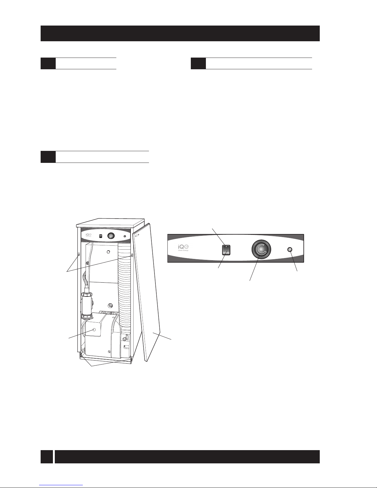
To gain acces to the controls, pull the front
panel forward at the top to disengage the
fixing clips then lift it up and off the boiler.
To replace locate the bottom of the panel
over the fixing tags then push it towards the
boiler to engage the fixing clips.
Fig. A Boiler controls
1 Ensure that - There is sufficient fuel, of the correct
type, in the supply tank and all fuel supply valves
are open. The
water supply is on. The electricity
supply to the boiler is off. The boiler On/Off switch
is set to OFF. The room thermostat (if fitted) is at
the desired setting. The boiler thermostat is set to
the required setting (see Section 2.7).
2 Switch on the electricity supply to the boiler.
3 Set the On/Off switch to ON and, if fitted, the
pro
gr
ammer (CH or HW) to ON.
The boi
ler will now light automatically.
4 If you have a programmer fitted in your system,
refer to the instructions supplied with the
programmer and set the programmer. Set the H
W
and CH functions to TIMED. The boiler will now
operate during the 'on' periods set on the
programmer.
Boiler
thermostat
Overheat
thermostat
reset button
(under cover)
On/Off
switch
OVERHEAT
RESET
HEATING
TEMPERATURE
OVERHEAT
RESET
BOILER
OFF
ON
HEATING
TEMPERATURE
ON
BOILER
OFF
Lock-out
button
Front panel removed
(pull forward at top, then
lift off)
Front panel
fixing clips
Front panel bottom locating tags
GRANT
Mains On
neon
iQE Horizon Internal Oil Boiler
2.1
About your boiler
2.3
Lighting your boiler (see Fig. A)
2.2
Boiler controls (see Fig. A)
Page 6
5
For short periods - Set the On/Off to OFF. To
restart, simply set the switch to ON.
For long periods: Set the On/Off switch to OFF
and switch off the electricity supply to the boiler.
If required, the fuel supply valve may be closed
and the water and electricity supplies turned off
at the mains.
To restart, refer to the full lighting instructions
given in Section 2.3.
1 Check that the
boiler On/Off switch is ON.
2 Check that the programmer (if fitted) is working
and is in an 'on' period.
3 Check that all thermostats are set to the desired
setting and are calling for heat.
4 Check if the burner 'Lock-out' reset button
(on the burner) is lit. If it is, press it to start the
burner. If the burner fails to light and goes to
'Lock-out' again, check that you have sufficient
fuel in the storage tank and that the fuel supply
valve is open. Check that the fire valve in the oil
supply line has not tripped
5 Ensure that a fuse has not blown or that the
electricity supply has not failed.
6 Check to see if the safety thermostat has operated
(see Section 2.7).
If the burner still fails to light after carrying out these
checks then a fault exists. Switch off the electricity
supply to the boiler and contact your Service
engineer.
iQE Horizon Internal oil boilers only operate on
Class C2 Kerosene to BS 2869:1998.
You should always quote this type of fuel when
ordering from your supplier.
Do not wait until the fuel runs out before you order
some more. Sludge in the bottom of the tank may be
drawn into the fuel lines. If it is possible, switch off
the boiler when the new supply is delivered and
leave the fuel to settle for an hour before restarting
the boiler.
2 - USER INSTRUCTIONS
1 Boiler thermostat - This control allows the
temperature of the water leaving the boiler to heat
the radiators and domestic hot water to be adjusted.
Note: If you have a cylinder thermostat on
your hot water cylinder, this will control the
temperature of your domestic hot water. The
boiler thermostat setting must be equal to or
above the cylinder thermostat setting to
enable the cylinder thermostat to control the
domestic hot water system.
2 Burner Lock-out reset button - If there is a
burner malfunction, a built-in safety circuit
switches the burner off and the 'Lock-out' reset
button (on the burner) will light. Usually such
malfunctions are short lived and pressing the
reset button will restore normal operation.
If the burner continually goes to 'Lock-out'
a fault exists or the fuel supply is low. If you
have sufficient fuel, you will need to call
your Service engineer.
3 Safety thermostat - Your boiler is fitted with a safety
heat thermostat which will automatically switch off
the boiler in the case of a control malfunction
causing overheating.
If your boiler goes off and you try to light it but
nothing happens and the 'Lock-out' reset
button on the burner is not lit, the overheat
thermostat has probably operated. The boiler
will not light until the thermostat is reset. To
reset, unscrew the small plastic cap (see
Fig.A), press the button then replace the cap. If
this condition continually repeats, contact your
Service engineer.
4 Programmer (if fitted) - Refer to the instructions
suppplied with the Programmer.
5 Ventilation - Always ensure that the boiler has
adequate ventilation. Any ventilation openings
provided by the Installer must not be obstructed.
Periodically check that they are clear.
Do not attempt to 'box in' the boiler or build
a compartment around it before consulting
your Installer.
Do not place any combustible material
around or on the boiler or flue pipe.
6 Flue terminal - The flue terminal on the outside wall
must not be o
bstructed or damaged.
In severe conditions check that the terminal
does not be
come blocked by snow.
iQE Horizon Internal Oil Boiler
2.7
General notes and care of your system
2.4
Turning off your boiler (see Fig. A)
2.5
Points to check if burner fails to light
2.6
About your fuel
Page 7
6
7 Frost protection - Your Installer may have fitted
a f
rost thermostat. If not, and you are likely to
be away for a short time, leave the boiler on
with the boiler thermostat set at a low setting.
For longer periods the boiler and system
should be drained. Contact your Service
engineer for draining and filling the system.
8 Cleaning and servicing - Lightly wipe over the
case with a damp cloth and a little deterg
ent.
Do not use abrasive pads or cleaners.
You must have your boiler serviced at least
once a year to ensure safe and efficient
operation. Contact your Service engineer for
further details.
9 Failure of electricity supply - If the electricity
sup
ply fails, the boiler will not operate. It should
re
light automatically when the supply is restored.
If
a programmer is fitted it will retain the time
settings for up to 24 hours and will not have
to be reset to the correct time of day when
the supply is restored (the display remains for
up to 1 hour, but will re-appear when the
supply is restored).
The boiler requires a 230/240 V ~ 50 Hz
supply. It must be protected by a 5 Amp fuse.
Warning: This appliance must be earthed.
If your boiler is operating on a sealed heating
system, the installer will have pressurised the
system and should have told you (or set it on the
pressure gauge) the system pressure when cold
(this is normally between 0.5 and 1.0 bar, which
will increase slightly when hot). If the pressure
(when cold) is below the set pressure mentioned
above, you can re-pressurise the system. If the
system requires frequent re-pressurising, ask your
Installer or Service engineer to check the heating
system for leaks and to check the expansion
vessel air charge.
The boiler or system will be fitted with an
automatic air vent to remove air from the system.
Any air trapped in the radiators should be
removed by venting the radiators using the vent
screw at the top of each radiator. Only vent a
radiator if the top is cool and the bottom is
hot. Excessive venting will reduce the system
pressure, so only vent when necessary and check
the system pressure as mentioned above. Repressurise the system if necessary.
2 - USER INSTRUCTIONS
Th
e boiler or system may be fitted with a safety
valve to release excess pressure from the system.
If water or steam is emitted from the end of the
safety valve discharge pipe, switch off the boiler
and contact your Installer or Service engineer.
Th
e expansion vessel air charge must be checked
annually. Failure to maintain an adequate air
charge in the vessel may invalidate the warranty.
To re-pressurise the system by adding water:
1 Only add water to the system when it is cold and
the boiler is off. Do not overfill.
2 Ensure the flexible filling loop (see Fig. B) is
con
nected and that the shut off valve connecting
it to the boiler is open and the double check
valve at the front is closed. A valve is open when
th
e operating lever is in line with the valve, and
close
d when it is at right angles to it.
3 Gradually open the double check valve on the front
of the filling loop until water is heard to flow.
W
hen the black needle of the pressure gauge is
between 0.5 and 1 bar, close the valve.
4 Vent each radiator in turn, starting with the lowest
one in the system, to remove air.
5 Continue to fill the system until the pressure gauge
indicates between 0.5 and 1.0 bar. Close the fill
point
valve.
6 Repeat steps 4 and 5 as required.
7 Close the valves either side of the filling loop and
disconnect the loop.
Sealed system filling loop arrangement - Fig. B
Central
heating
system
Mains
water
supply
Pressure gauge
Double check valve
Shut off valve
Flexible filling hose
iQE Horizon Internal Oil Boiler
2.8
Electricity supply
2.9
Sealed central heating system
Page 8
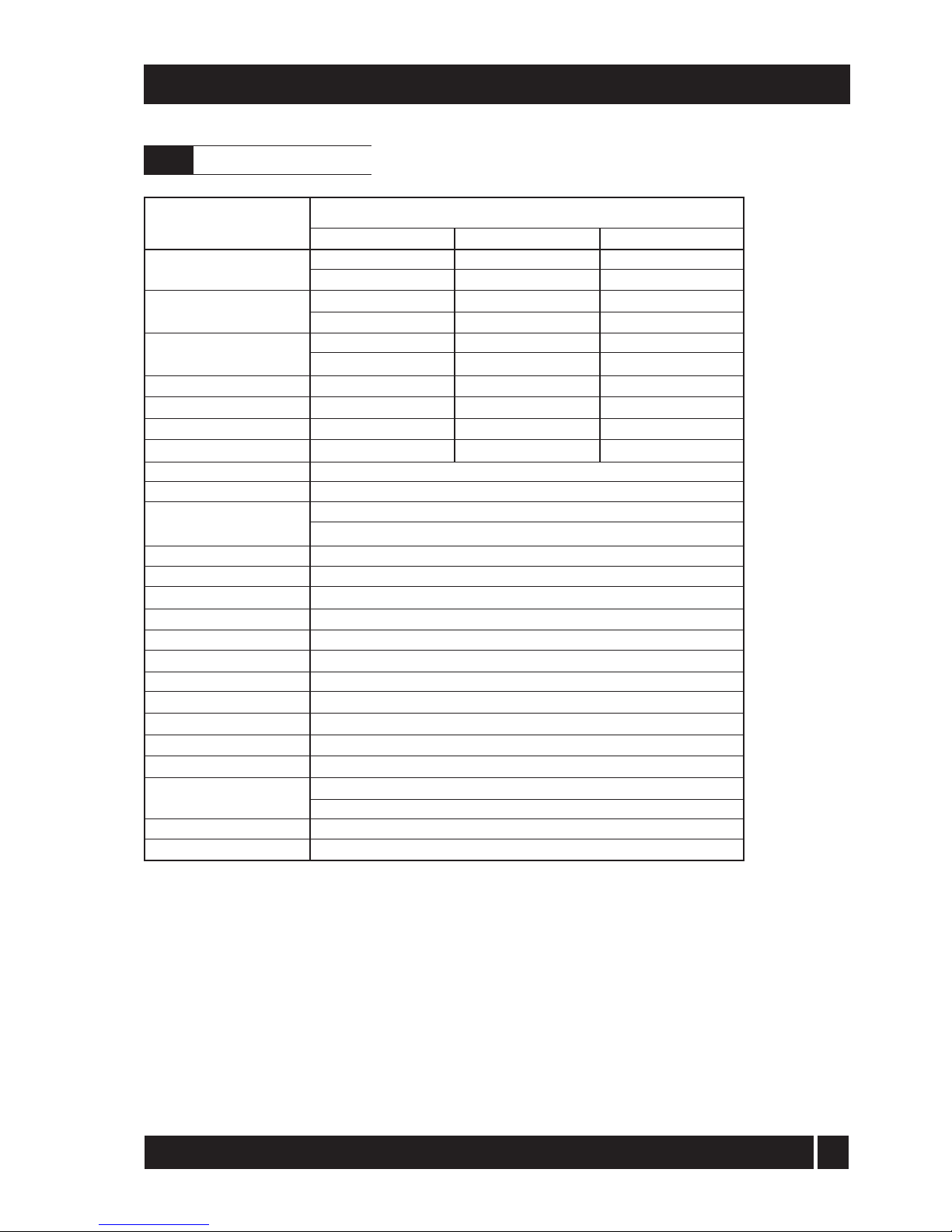
7
25.6
87350
22 mm
22 mm
1 780
1 100
22 mm (only connect
plastic pipe) 100 mm
28.5 mbar
10 mbar
28 m
1m
65 to 75° C
111° C ± 3° C
Less than 50° C
230/240 V ~ 50 Hz Fused at 5 Amp
90
4.2
0.85
¼" BSP Male (on end of flexible fuel
hose) Minimum flue draught - 8.7 N/m²
(0.035 in wg) Maximum flue draught -
37 N/m² (0.15 in wg) 2.5 bar
2.5 bar
3- BOILER TECHNICAL INFORMATION
Model
Water content litre
gal
* Weight (dry) kg
lb
Max. heat output kW
(kerosene) Btu/h
Flow connection
Return connection
Min. flow rate (ΔT=10°C) l/h
Min. flow rate (ΔT=20°C) l/h
Condensate connection
Flue diameter (conventional)
Waterside resistance
Flow/Return temp. diff. of 10°C
Flow/Return temp. diff. of 20°C
Maximum static head
Minimum circulating head
Boiler thermostat range
Limit (safety) stat shut off temp
Max. hearth temperature
Electricity supply
Motor power Watts
Amps
Amps
Starting current
Running current
Oil connection
Conventional
flue
Max operating press - sealed sys
Max operating press - open sys
* Weight includes burner but excludes flue.
iQE Horizon
Internal 15/26
13
2.9
103
227
26/35
19
4.2
121
267
34.7
118400
22 mm
22 mm
2 980
1 490
iQE Horizon Internal Oil Boiler
3.1
Boiler technical data
Page 9
8
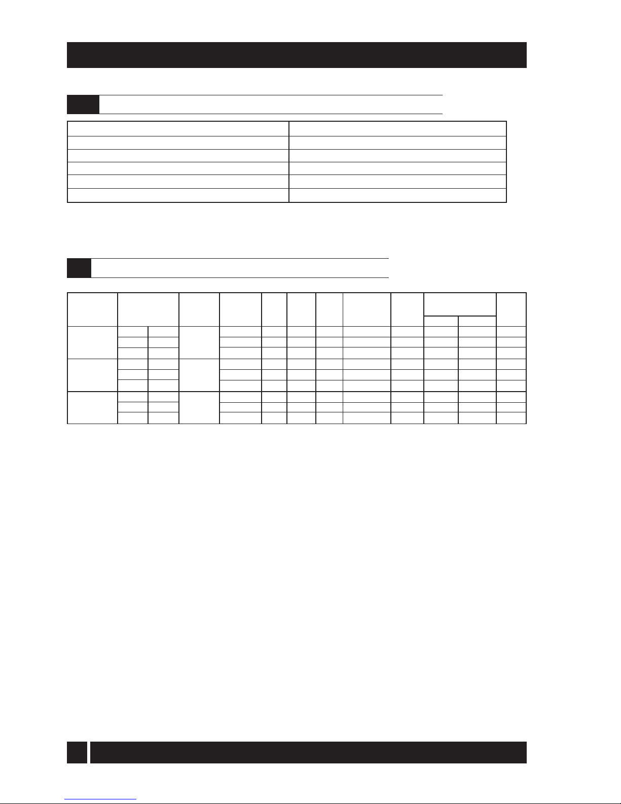
3 - BOILER TECHNICAL INFORMATION
Note: iQE boilers are only for use with kerosene.
(kW)
15.1
18.1
20.7
22.7
25.6
25.6
30.8
34.7
(
Btu/h)
51 500
61 750
70 600
77 500
87 350
87 350
105 100
118 400
Model and Heat Output
Nozzle
0.50/80°EH
0.55/80°EH
0.60/80°EH
0.65/80°EH
0.75/80°EH
0.75/80°EH
0.85/80°EH
1.00/80°EH
Oil
press.
(bar)
7.5
7.5
8.5
8.5
8.0
8.0
9.1
8.0
Smoke
No.
0 - 1
0 - 1
0 - 1
0 - 1
0 - 1
0 - 1
0 - 1
0 - 1
Fuel flow
rate
(kg/h)
1.29
1.53
1.78
1.95
2.19
2.19
2.65
2.93
Flue
70 - 75
75 - 80
85 - 90
85 - 90
90 - 95
75 - 80
85 - 90
90 - 95
CO
2
(%)
11 - 12
11 - 12
11 - 12
11 - 12
11 - 12
11 - 12
11 - 12
11 - 12
15/26
Riello RDB2.2
15/26
Riello RDB2.2
26/35
Riello RDB2.2
burner type
Heating system pressure (cold)
Operating pressure of pressure relief valve
Expansion vessel size
Max heating system volume (including boiler)*
Cold water mains connection (for filling loop)
Pressure relief valve discharge connection
Maximum 1.0 bar, Minimum 0.5 bar
2.5 bar
12 litres (pre-charged at 1 bar)
128 litres (approximately)
15 mm compression (provided)
15 mm compression (provided)
* Based on vessel charge and system cold fill pressure of 0.5 bar
SEDBUK
efficiency
(%)
93.0
92.4
92.1
Disc setting B
Disc setting C
Fixed
Fixed
Fixed
Fixed
Fixed
Fixed
Burner
head/disc
setting
*
*
Notes:
1 The data given above is approximate only and based on the boiler using a low level flue.
2 The above settings may have to be adjusted on site for the correct operation of the burner.
3 Gas Oil is not suitable for use with the iQE boiler range.
4 The net flue gas temperatures given above are ± 10%.
5 When commissioning the air damper must be adjusted to obtain the correct CO2 level.
6 *
F
actory settings: 15/21 - 18.1 kW, 21/26 - 22.7 kW, 26/35 - 30.8 kW.
7 The combustion door test point may be used for CO2 and smoke readings only. Do not use this test point for
temperature o
r efficiency readings.
8
9
W
hen setting the 15/26 to 15.1 kW output a burner air adjuster disc requires positioning. Refer to Section 7
Commissioning.When setting the 26/35 to 25.6 kW output the combustion head must be changed.
Refer to Section 9.4 Cleaning the burner.
The installer must amend the boiler data label if the output is changed.
Flue gas analysis
To allow the boiler to be commissioned and serviced, the boiler is supplied with a combustion test point on the front
cleaning door. When this test point is used please note the following:
1. The test point is for CO2 and smoke readings only.
2. The boiler efficiency and temperature must be taken from the flue test point on high level and vertical flue adaptors.
3. Low level flues do not contain a test point. The temperature and efficiency readings must be taken from the flue terminal.
Burner
head
type
T1
T1
T1
T2
T2
T2
T3
T3
Flue gas temp °C
Door
155 - 160
175 - 180
195 - 200
205 - 210
215 - 220
190 - 195
215 - 220
220 - 225
Danfoss
iQE Horizon Internal Oil Boiler
3.2
Sealed system data - iQE Horizon models with sealed system kit
3.3
iQE Horizon Internal oil boilers using Class C2 kerosene
Page 10

9
3 - BOILER TECHNICAL INFORMATION
Fig. 1b - 26/35 dimensions
Fig. 1a - 15/26 dimensions
61
82
170
61
86
LEFT SIDE VIEW
587
19
115
60
25
Flue centre line
RIGHT SIDE VIEW
PLAN VIEW
470
603
150
FRONT VIEW
470
441
250
900
696
205
Flue
spigot
Alternative
condensate
drain outlets
624
17
REAR VIEW
430
200115
125
860
705
RIGHT SIDE VIEW
200
28
125
813
712
17
LEFT SIDE VIEW
110
605
Flue centre line
Flue centre
line
Alternative
condensate
drain outlets
177
88
445
PLAN VIEW
430
605
110
iQE Horizon Internal Oil Boiler
3.4
Boiler dimensions
Page 11

10
4 - GENERAL BOILER INFORMATION
iQE G-system ...... Standard external high level/
vertical flue starter kit (room sealed) components available:
Ex
te
rnal high level/vertical flue starter kit
short (room sealed)
Extensions 150 mm, 250 mm, 450 mm, 950
mm, adjustable 195 to 270 mm and 45° elbow
High level terminal
Vertical terminal
iQE W-system ...... High level and vertical concentric
balanced flue kit - components available:
Extensions 225 mm, 450 mm, 950 mm,
adjustable 275 to 450 mm and 45° elbow
Vertical concentric balanced flue kit
Extensions 225 mm, 450 mm, 950 mm,
adjustable 275 to 450 mm and 45° elbow
iQE R-system (15/26 only) ..... A flexible
vertical balanced flue system designed to be
fitted inside an existing masonry chimney.
Flue extensions and 45° elbows from the
iQE W- system may be used to extend the
flue system between the boiler and the
flexible section of the system.
A
ll burners are pre-se
t for use with kerosene and
are supplied ready to connect to a single pipe fuel
supply sys
tem with a loose flexible fuel line and male
adaptor supplied with the boiler.
If required, an additional flexible fuel line
(600mm) and BSP male adaptor (1/4" x 3/8")are
available to purchase from iQE.
The temperature of the water leaving the boiler
to heat the radiators and hot water cylinder is
User adjustable.
The boiler is fitted with an overheat thermostat
(which allows it to be used on a sealed central heating
system) which will automatically switch off the boiler
if the heat exchanger exceeds a pre-set temperature
of 111° C ± 3° C.
The control panel is fitted with an ON/OFF
switch, boiler thermostat control knob and the
manual reset button for the overheat
thermostat.
4.2
Boiler components
The
iQE Horizon Internal range of automatic
pressure jet oil boilers have been designed for use
with a fully pumped central heating system with
indirect domestic hot water cylinder. They are not
suitable for use with either a direct cylinder or a
'primatic' cylinder or gravity hot water.
The boilers are suitable for use on open vented or
sealed central heating systems. System models are
supplied with the necessary components factory
fitted. See Section 4.13.
All models are supplied with the control panel and
burner factory fitted.
The boilers can be connected to either a conventional
flue system or a balanced flue system, as required.
For Conventional flue applications where a
chimney is to be lined - iQE recommends the use
of the O-system, specifically designed for the
Internal range of iQE Horizon oil boilers. Refer to
Section 4.7 for further details.
Where a rigid conventional flue - either internal or
external - is required, iQE recommends the use of
the G and O flue system components. As no flue
adaptor is supplied with the boiler it will be
necessary to purchase the iQE Horizon adaptor
kit in order to correctly connect the G and O
system flue components to the boiler.
Flue adaptor kit - Ref. iQE CF15/35 - is used for all
iQE models from 15 to 35 kW as they all can use the
100 mm G and O system components to
construct a flue of maximum vertical height 8
metres.
Important: The flue system materials and
construction MUST be suitable for use with oilfired condensing boilers. Failure to fit a suitable
conventional flue may invalidate the warranty on
the boiler.
Fitting instructions for the Low level concentric, High
level and Vertical balanced flue kits are supplied
with the kits. Where a balanced flue system is
required, the following flue kits are available
from iQE,
Refer to Section 4.8 for further details.
iQE Y-system ..... Standard low level concentric
balanced flue - components available:
Low le
vel concentric balanced flue short
Extensions 225 mm, 450 mm and 675 mm
90° extension elbow
45° extension elbow
45° elbow
iQE Horizon Internal Oil Boiler
4.1
Boiler description
Page 12

11
The installation should also be in accordance with
the latest edition of the following British Standard
Codes of Practice:-
BS 715 Metal flue pipes, fittings, terminals
and accessories.
BS 799:5
Oil storage tanks.
BS 1181
Clay flue linings and flue terminals.
BS 4543:3 Factory made insulated chimneys for
oil fire
d appliances.
BS 4876
Performance requirements for oil
burning appliances.
BS 5410:1 Code
of Practice for oil firing appliances.
BS 5449
BS 7593
Forced circulation hot water systems.
Code of Practice for treatment of
BS 76
71
water in heating systems.
Requirements for electrical installations,
IEE Wiring Regulations.
Failure to install and co
mmission appliances
correctly
may invalidate the boiler warranty.
IMPORTANT
Before starting any work on the boiler, or fuel
supply please read the health and safety
information given in Section 14 on page 47.
4.4.1 Fuel storage
The tank should be positioned in accordance
with the recommendations given in BS 5410:1:1997,
which gives details of filling, maintenance and
protection from fire.
A
steel tank may be used and must be constructed
to
BS 799:5:1987 and OFS T200.
A galvanised tank must not be used.
A plastic tank may be used and must comply
with OFS T100.
Note: Plastic tanks should be adequately and
uniformly supported on a smooth level surface,
across their entire base area.
Inst
allation of a iQE Horizon Internal boiler must
be in accordance with the following
recommendations:-
a Building
Regulations for England and Wales,
an
d the Building Standards for Scotland
issued by the Department of the Environment
and any local Byelaws etc.
b Model and local Water Undertaking Byelaws.
c A
pplicable Control of Pollution Regulations.
d T
he following OFTEC requirements:-
OFST 100 Polythene
oil storage tanks for
d
istillate fuels.
OFST 200
Fuel oil storage tanks and tank
bunds for use with distillate
fuels,lubrication oils and waste
oils.
4
- GENERAL BOILER INFORMATION
Regional statutory requirements may deem this appliance to be a 'controlled service'.
Where this is the case, it is a legal requirement that the appliance is installed and
commissioned either under the remit of building control or by a 'Competent person' such
as a suitably qualified Oftec registered technician.
Fig. 2 - Components
OVERHEAT
RESET
HEATING
TEMPERATURE
ON
BOILER
OFF
Lock-out
button
Front panel
removed
(pull forward
at top, then
lift off)
Front panel
fixing clips
Condensate
trap
Front panel bottom locating tags
GRANT
Air supply
tube
Burner
iQE Horizon Internal Oil Boiler
Further information may be obtained from the
OFTEC Technical Information Book 3
(Installation requirements for oil fired boilers and
o
il storage tanks).
4.4
Fuel supply
4.3
Regulations to comply with
Page 13
12
4 - GENERAL BOILER INFORMATION
4.4.2 Fuel pipes
1 Fuel supply pipes should be of copper tubing
with an external diameter of at least 10 mm.
Gal
vanised pipe must not be used.
All pipe connections should preferably use flared
fittings. Soldered connections must not be used
on oil pipes.
2 Flexible pipes must not be used outside the boiler case.
3 A remote sensing fire valve must be installed in
the fuel supply line (outside) where it enters the
bu
ilding, with the sensing head located above
the burner. Recommendations are given in BS
5410:1:1997.
4 A metal bowl type filter with a replaceable micronic
filter must be fitted in the fuel supply line adjacent
to the boiler.
A shut-off valve should be fitted
before the filter, to allow the filter to be serviced.
5 A flexible fuel hose, adaptor and 1/4" BSP isolation
valve are supplied loose with the boiler for the
final connection to the burner. If a two pipe
system or 'Tiger Loop' type de-aerator is used,
an additional flexible fuel hose (600 mm) and
male adaptor are available to purchase from
iQE.
6 Metal braided flexible hoses should be replaced
annually when the boiler is serviced. Long life
flex
ible pipes should be inspected annually
and replaced at least every 60 months.
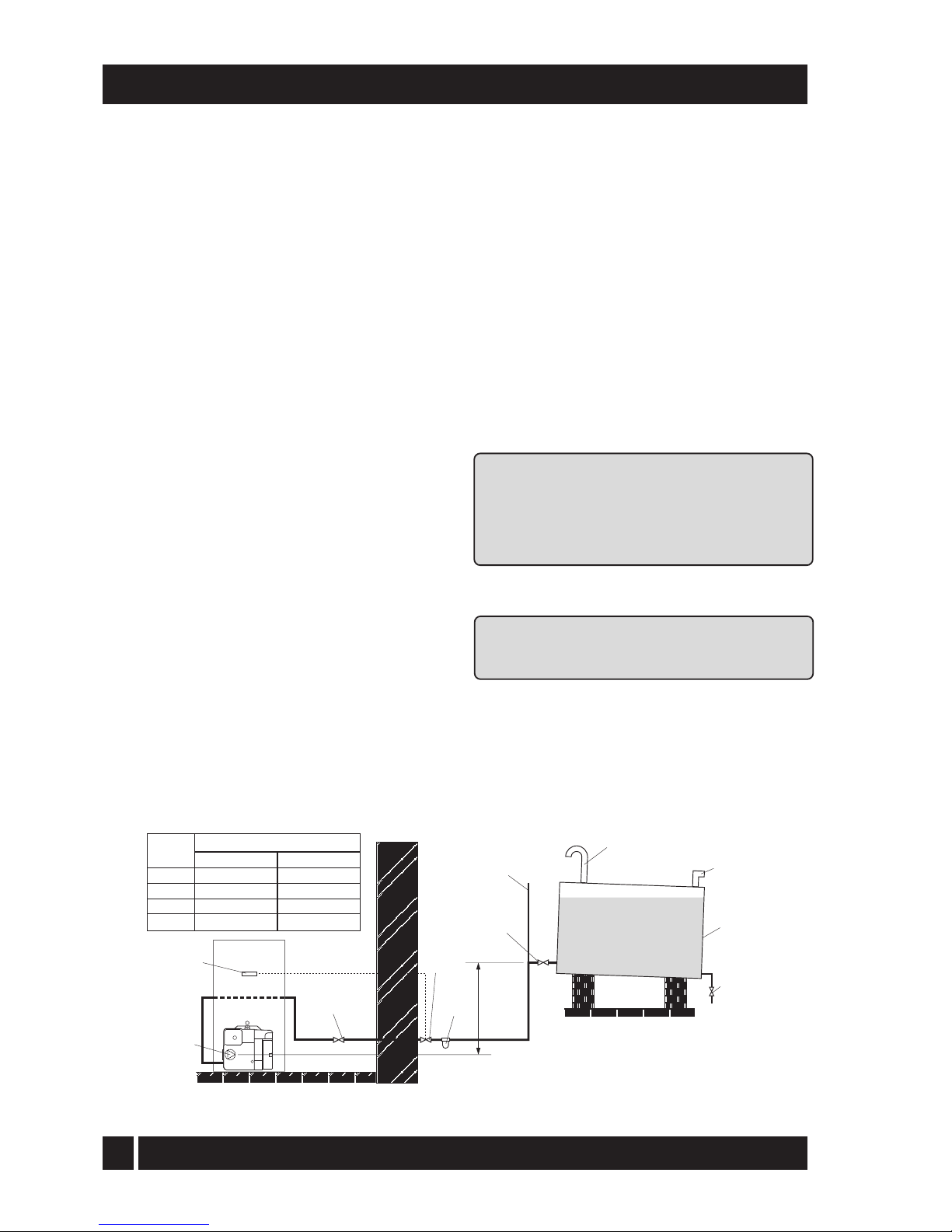
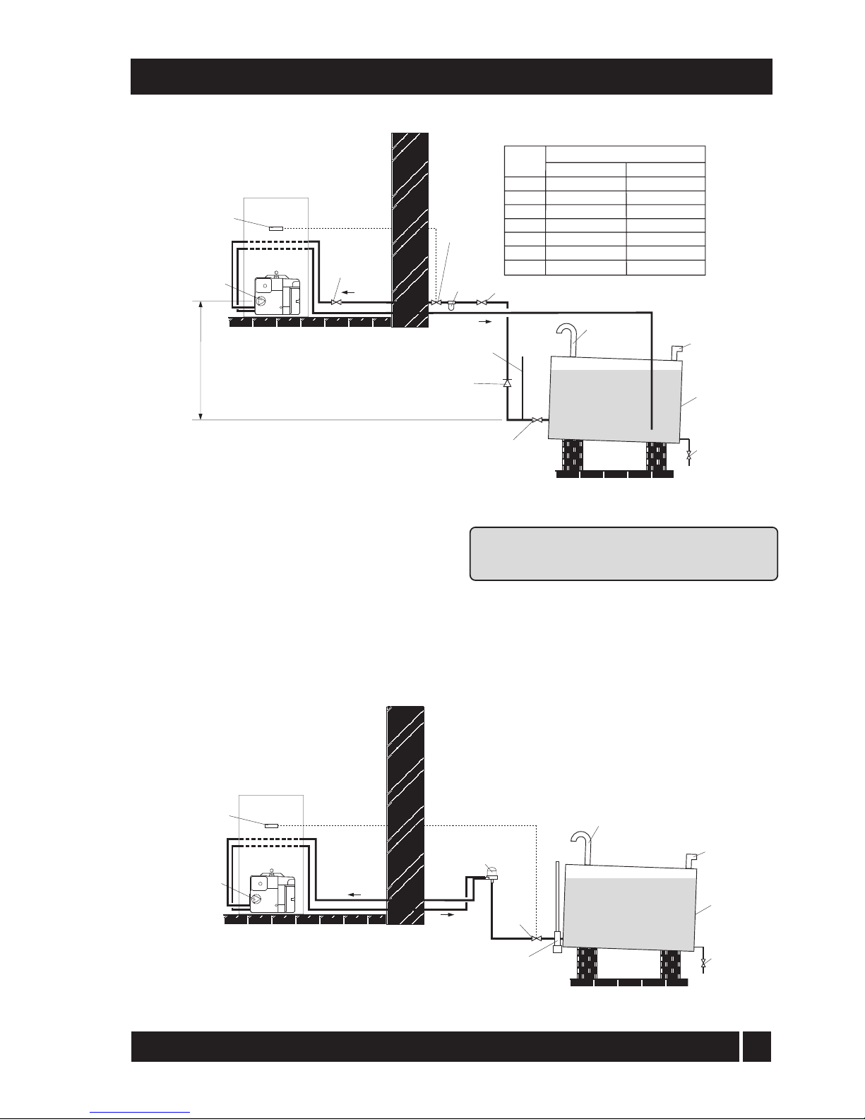
4.4.3 Single pipe system - (See Fig. 3)
1 Where the storage tank outlet is above the burner
the single pipe system should be used. The
height of the tank
above the burner limits the
length of pipe run from the tank to the burner.
2 As supplied the burner is suitable for a single pipe system.
4.4.4 Two pipe system - (See Fig. 4)
1 When the storage tank outlet is below the burner,
the two pipe system should be used. The pipe
runs should be as shown in Fig. 4. The return
p
ipe should be at the same level in the tank as
the supply pipe, both being 75 to 100 mm
above the base of the tank. The pipe ends
should be a sufficient distance apart so as to
prevent any sediment disturbed by the return
entering the supply pipe.
2 Avoid the bottom of the tank being more than 3 m
below the burner.
3 A non-return valve should be fitted in the supply
pip
e together with the filter and fire valve. A
non-return valve should be fitted in the return
pipe if the top of the tank is above the burner.
4 T
o be used with a two-pipe system,
the burner must be fitted with an additional
flexible fuel hose and a male adaptor. They are
available to purchase from iQE. Part No.
iQELINE / iQE3814
5 The pump vacuum should not exceed 0.4 bar.
Beyond
this limit gas is released from the oil.
For guidance on installation of top outlet fuel
tanks and suction oil supply sizing, see OFTEC
booklet T1/139. Available at www.oftec.org.uk.
Fig. 3 - Single pipe system
Filter
Fire
valve
Shut-off
valve
Shut-off
valve
A
Sludge
valve
Fill
pipe
Vent
pipe
Level
gauge
Fuel
storage
tank
Fire
valve
sensor
Pump
Head A
(m)
Maximum pipe run (m)
0.5
1.0
1.5
2.0
10mm OD pipe
10
20
40
60
12mm OD pipe
20
40
80
100
iQE Horizon Internal Oil Boiler
Page 14
13
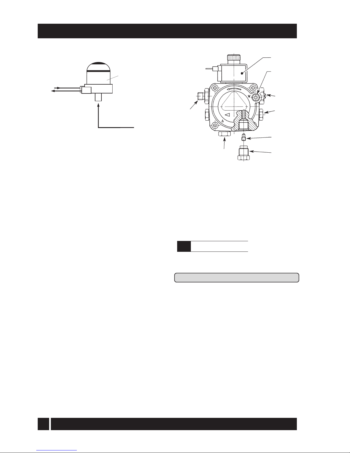
Fig. 5 - De-aeration device system
4.4.5 Tiger Loop system - (See Figs. 5 and 6)
1 When The storage tank is below the burner, an alternative
to a two pipe syste
m can be achieved using a 'Tiger
Loop' type oil de-aerator (iQEDEAER). This
effectively removes the air from the oil supply on a
single pipe lift.
2 The de-aerator is connected close to the boiler as a
two pipe system (omitting the non-return valve) as
shown in Fig. 5. Refer to the manufacturers
instructions supplied with the de-aerator.
The de-aerator must be mounted vertically.
4 - GENERAL BOILER INFORMATION
Fig. 4 - Two pipe system
Note: To prevent any possibility of fuel fumes
entering the building, the de-aerator must be
fitted outside.
3 To be used with a de-aerator, the burner must be
fitted with an additional flexible fuel hose (a
f
lexible fuel hose (600 mm) and 3/8" to 1/4"
BSP male adaptor are available to purchase
from iQE.
Filter
Fire
valve
Shut-off
valve
Shut-off valve
Shut-off
valve
See
section 4.4.6
A
Return
Supply
Head A
(m)
Maximum pipe run (m)
0
0.5
1.0
1.5
2.0
3.0
3.5
10mm OD pipe
35
30
25
20
15
8
6
12mm OD pipe
100
100
100
90
70
30
20
Non
return
valve
Fire
valve
sensor
Sludge
valve
Fill
pipe
Vent
pipe
Level
gauge
Fuel
storage
tank
Fire
valve
Tankmaster
See
section 4.4.6
Sludge
valve
Fill
pipe
Vent
pipe
Fuel
storage
tank
De-aeration
device e.g. Tiger
Loop See Fig. 6
Fire
valve
sensor
Return
Supply
iQE Horizon Internal Oil Boiler
Page 15
14
4.4.6 Two pipe oil supplies
Riello RDB burner - See Fig. 7
1 The fuel pump is supplied for use with a single
pip
e fuel supply system. For use on a two pipe
system, it is necessary to fit the By-pass screw
(see Fig. 7) into the tapping in the return port.
2 The By-pass screw is supplied in the boiler
accessory pack.
3 Remove the plastic burner cover (secured by
two screws). To gain access, it may be
necessary to remove the plinth - loosen the
screw securing
the right hand side of the plinth,
then withdraw the plinth forward from the right
and away from the case.
4 Remove and discard the blanking plug from the
return connection of the pump and fit the
By-pass screw using an hexagonal key.
5 Connect the return oil flexible fuel hose to the pump.
6
C
onnect the male adaptor to the flexible fuel hose
Fig. 6 - Tiger loop 'de-aeration' device
4 - GENERAL BOILER INFORMATION
Fig. 7 - Riello RDB pump
1 Oil inlet connection
2 Re
turn connection
3 By-pass screw
4 Pres
sure gauge connection
5 Pressure adjuster
6 Vacuum gauge connection
7 Solenoid
8 Supply to nozzle
4.5
Electricity supply
1 A 230/240 V ~ 50 Hz mains supply is required.
Refer to Section 10 for connection details.
Th
e boiler must be earthed.
2 The supply must be fused at 5 Amp and there must
only be one common isolator for the boiler
and control system, providing complete
electrical isolation.
3 A fused double pole switch or a fused three pin
plug and shuttered outlet socket should be
used for the connection.
4 The power supply cable should be at least 0.75 mm²
PVC as specified in BS 6500, Table 16.
5 All the wiring and supplementary earth bonding
external to the boiler must be in accordance
with the current I.E.E. Wiring Regulations.
6 Any room thermostat or frost thermostat used must
be suitable for use on mains voltage.
7 In the event of an electrical fault after installation
of the boiler, the following electrical system
checks must be carried out:- Short circuit,
Polarity, Earth continuity and Resistance to
earth.
1/4" BSP
female
connections
Tiger Loop
SUPPLY
TO PUMP
RETURN
FROM PUMP
SUPPLY
FROM TANK
1
2
3
4
5
6
7
8
iQE Horizon Internal Oil Boiler
Page 16
15
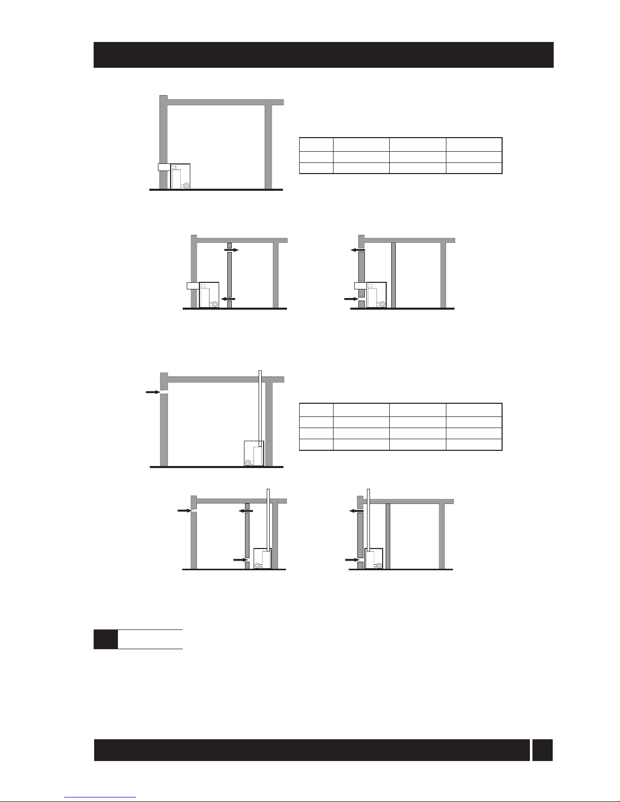
BOILER IN
ROOM
Conventional open flue
C
BOILER IN
COMPARTMENT
Conventional open flue
compartment ventilated from room
Conventional open flue
compartment ventilated from outside
C
C
D
D
E
BOILER IN
ROOM
Room sealed balanced flue no
ventilation required to room
BOILER IN
COMPARTMENT
Room sealed balanced flue
compartment ventilated from room
Room sealed balanced flue
compartment ventilated from outside
B
B
A
A
Fig. 8 - Air supply for room sealed balanced flue boilers
4 - GENERAL BOILER INFORMATION
Fig. 9 - Air supply for conventional flue boilers
15/21 kW
116 cm² (18 in²)
232 cm² (36 in²)
26/35 kW
198 cm² (31 in²)
396 cm² (62 in²)
Output
Vent A
Vent B
15/21 kW
116 cm² (18 in²)
232 cm² (36 in²)
348 cm² (54 in²)
26/35 kW
198 cm² (31 in²)
396 cm² (62 in²)
594 cm² (93 in²)
Output
Vent C
Vent D
Vent E
See Figs. 8 and 9
A sufficient permanent air supply to the
boiler should be provided:
a For proper combustion of fuel and
effective discharge of combustion
products to the open air.
b For the ventilation of any confined space in
which the boiler is installed to prevent
overheating of the boiler any
equipment in and near the boiler.
21/26 kW
143 cm² (23 in²)
286 cm² (46 in²)
429 cm² (69 in²)
21/26 kW
143 cm² (23 in²)
286 cm² (46 in²)
iQE Horizon Internal Oil Boiler
4.6
Air supply
Page 17
16
4 - GENERAL BOILER INFORMATION
It should be both the designer's and installer's
concern that the air required for these functions
be introduced s
o as to cause as little discomfort
as possible to the building occupants and thus to
offer them the least temptation to obstruct the
ventilators.
Further details may be obtained from BS 5410:1:19
97.
Notes:
For a boiler fitted in a compartment, which
is v
entilated as shown, no additional
allowance is necessary. Open flue - Extract
fans, where needed, should be in
accordance with Section 4.4.7 in BS 5410
Part 1 1997. All ventilation areas given are
for domestic applications. For all other
cases refer to BS 5410 Part 2 1978.
Under no circumstances can iQE Horizon boilers
be installed with existing flue systems. Only flue
systems and components suitable for wet flues
should be used. Failure to install the correct type
of flue system will invalidate the warranty.
See Fig. 10a and 10b General
iQE
Horizon condensing boilers have high
operating efficiencies and low flue gas
temperatures. Care must be taken to ensure the
flue system is suitable for the very low flue gas
temperatures and condensate in the flue gases.
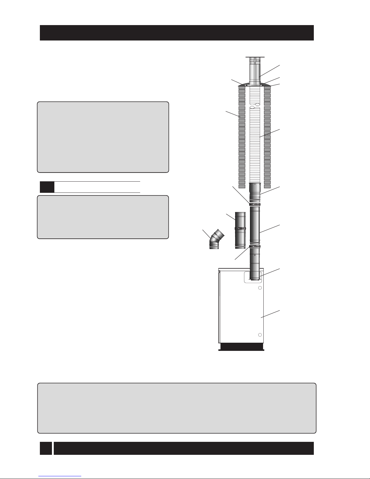
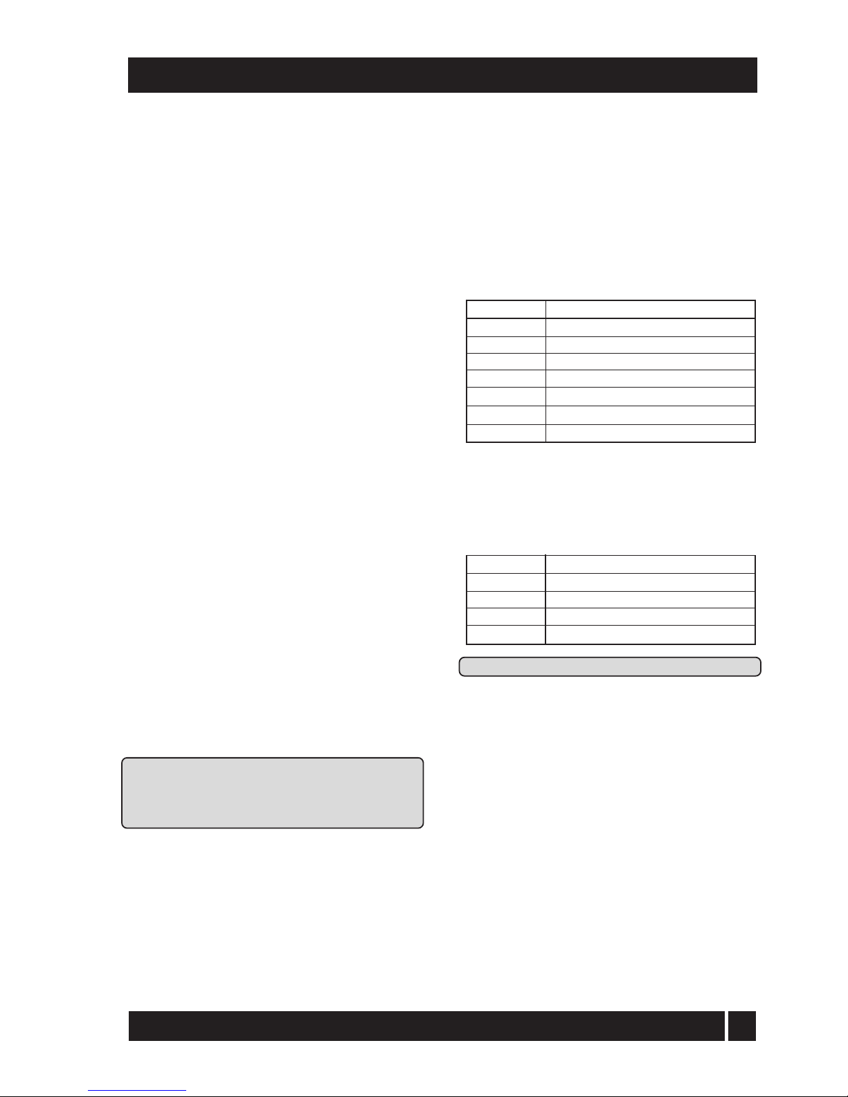
Suitable conventional flue systems (O-system) are
available from iQE - see Fig. 10a.
1 The flue must terminate in a down
draught free area,
i.e. at least 600 mm above the point of exit through
t
he roof or preferably above the ridge level.
2 The condensate may be allowed to run back into
the boiler. A condensate drain at the base
of
the flue system is not required.
3 Th
e flue terminal must be at least 600 mm from
any opening into the building, and 600 mm above
any vertical structure or wall less than a horizontal
distance of 750 mm from the terminal. See Fig. 11.
4 If an existing chimney is to be used, it must be lined
with a smooth bore stainless steel liner
suitable for use with oil fired condensing
boilers. The top and bottom of the annular
space must be sealed.
The internal flue and liner diameter for all
models must be 100 mm (4 in).
i
QE recommends the use of the iQE 'O' flue
system; specifically designed for the Internal
range of condensing boilers. Refer to Section
4.7 for further details.
The maximum vertical height (from the top
of the boiler to the terminal) for the iQE 'O'
system is 19 metres.
Fig. 10a - iQE 'O' system in a
typical brick chimney
Brick
chimney
Flaunching
Locking band
Rigid to flexi flue
connector (bottom)
Note: This component
must be installed
vertically
Extension
Boiler flue
connector
Boiler
Flexi pack
Terminal
Adjustable section 235/300mm
WXA250/100
WXA250/125
100mm dia.
125mm dia.
Locking band
C
45 elbow
O
Top plate
Clamp
iQE Horizon Internal Oil Boiler
4.7
Conventional flue system
Page 18
17
5 If a r
igid flue is used internally or externally,
it must be of the twin-wall type incorporating
seals
at all joints, constructed with a stainless steel
inner skin and be suitably insulated and
weatherproofed. iQE recommends the use of the
G flue system components for this application.
Refer to Section 4.1 for details. The internal flue
diameter for a rigid flue for all models is 100 mm
(4 in).
Note: As no flue adaptor is supplied with the boiler
it will be necessary to purchase the iQE CF adaptor
kit (Ref. iQE CF15/35) in order to correctly
connect the G-system flue components to the
boiler.
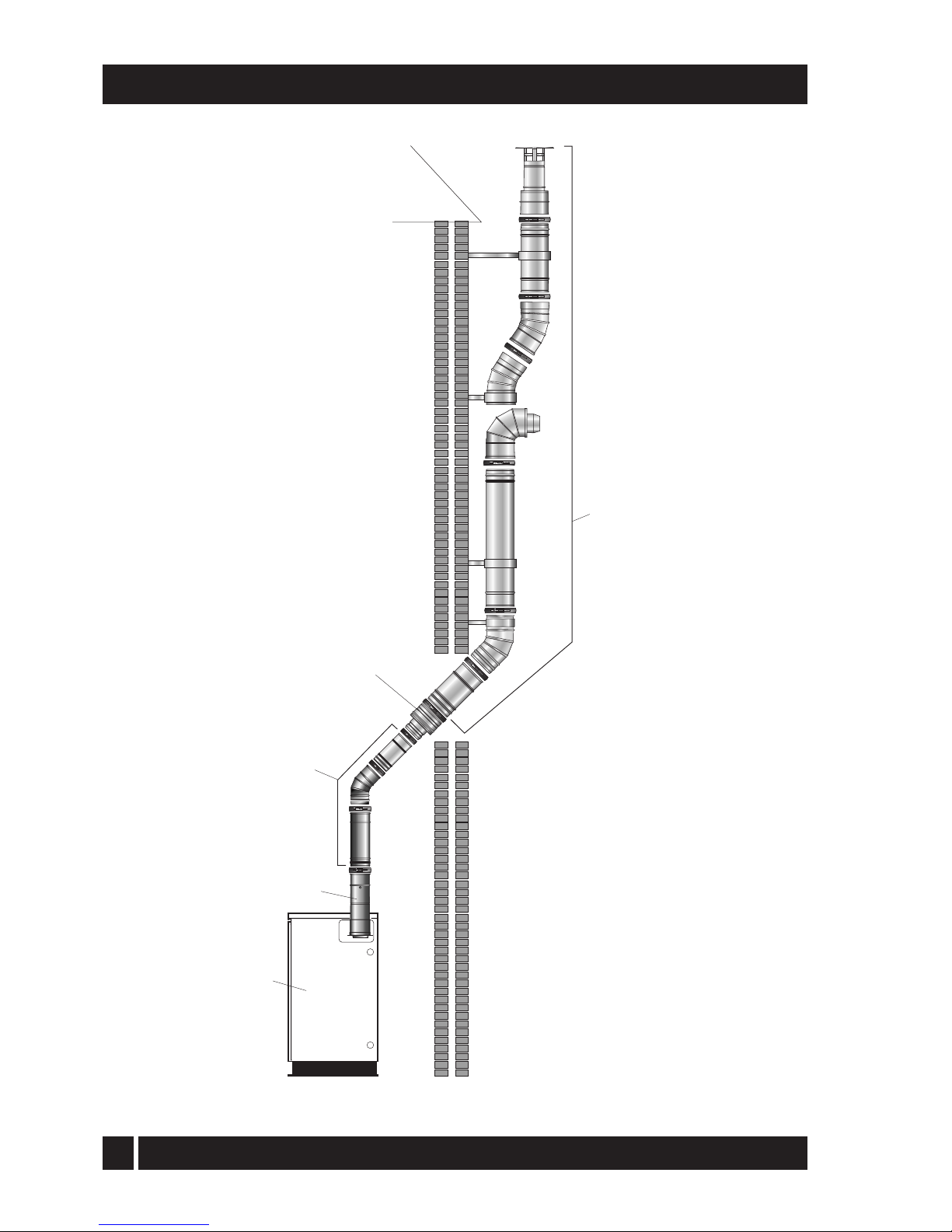
If required, it is possible to use the white
painted single-wall straight flue extensions,
adjustable extensions and elbows from the iQE Osystem for the internal section of the flue
system, see Fig 10b. These components can be
fitted between the boiler connector and flue
adaptor. The flue adaptor, to which the
external twin-wall G-system components are
connected, can therefore be situated just before
the flue system passes through the wall. Note:
iQE O-system single-wall flue components must
not be used externally.
The maximum vertical height (from the top of the
boiler to the terminal) for the 100 mm diameter
G-system twin-wall flue is 8 metres.
6 Twin-wall flues are recommended for externally
run flues to reduce the possibility of the
condensate freezing in the flue.
7 No part of any flue system should be made of an
asbestos material; alumini
um must not be
used in any part of the flue. Only stainless
steel flue components should be used.
8 If the draught conditions are satisfactory, the flue
should terminate with a standard cowl.
9 Refer to the locally applicable Building
Regulations, BS 5410:1 and OFTEC Installation
Requirements (Books 2 and 3) for further
guidance on conventional flue systems.
It is important to ensure that the flue system is
sealed and that condensate cannot escape. Up to
1.5 l/h of condensate can be produced in a
conventional flue system.
On
ly use flue systems suitable for oil fired
condensing boilers.
Do not use fire cement. The use of high temperature
silicone sealants is recommended.
4 - GENERAL BOILER INFORMATION
iQE O-System conventional flue
system - See Fig. 10a
A range of Flexible conventional flue lining kits
are available from iQE. The packs have been
specifically produced for iQE Horizon oil fired
condensing boilers.
Contents of iQE O-System flue pack
The pack includes a terminal/top plate/flexi flue
adaptor, stainless steel smooth bore flexible flue liner,
a rigid to flexi adaptor and a boiler flue connector.
Extensions
A range of white powder coated single wall
extensions are available to connect the boiler to
the flexible liner. The external diameter of the
extensions is 100 mm. Extensions are supplied
with locking bands.
Flue extension
s cannot be cut.
An adjustable extension and 45° elbow are
also available. See Figs. 10a and 10b.
The rigid flue between the boiler and flexible flue
liner should incorporate an adjustable section to
allow inspection and cleaning of the flue system.
Part No.
iQEO6
iQEO8
iQEO10
iQEO11
iQEO12
iQEO14
iQEO16
iQE O System
100mm dia. x 6 metre
100mm dia. x 8 metre
100mm dia. x 10 metre
100mm dia. x 11 metre
100mm dia. x 12 metre
Part No.
iQEOEX150
iQEOEX250
iQEOEX450
iQEOEX950
Extensions for iQE O System
1
00 mm dia. x 150 mm
100 mm dia. x 250 mm
100 mm dia. x 450 mm
100
mm dia. x 950 mm
iQE Horizon Internal Oil Boiler
100mm dia x 14 metre
100mm dia x 16 metre
Page 19
18
4 - GENERAL BOILER INFORMATION
Fig. 10b - H
-system using iQE O and iQE G -system components
iQE G-System
components
(refer to Fig. 10c)
iQE O-System
components
(refer to Fig. 10a)
Boiler flue connector
(from iQE CF15/35)
Adaptor
(from iQE CF15/35)
Boiler
iQE Horizon Internal Oil Boiler
Page 20

19
4 - GENERAL BOILER INFORMATION
Apa
rt from a conventional flue, several balanced flue
options are available for use with the iQE Internal
boilers. All are suitable for use with Class C2 kerosene.
Note: None of the flue sections in the
following system can be cut.
1 Low level horizontal balanced flue (iQE Y-system)
Available in Short (for single thickness brick
walls) and Standard kits.
Extensions are available which extend the
flue by 225 mm, 450 mm or 675 mm. 90° and
45° elbows are also available.
The
maximum flue length - from the centre of
the boiler flue outlet to the outer face of the wall
- is 4 metres (with or without elbows included).
No more than 2 x 45° or 1 x 90° elbow should be
fitted per system.
2 High level balanced flue (iQE W-system)
Allows the flue to rise vertically within the
building before exiting through the wall
horizontally.
The maximum flue length - from the top of the
boiler flue outlet to the outer face of the wall is 10 metres for all iQE boilers.
Extensions are available which extend the
flue by 225 mm, 450 mm or 950 mm. An
adjustable extension of 275 to 450 mm is
also available.
A 45° elbow is also available. No more than 6 x
45°elbows should be fitted per system. Each
elbow reduces the overall maximum length of the
system by 1 metre.
3 Vertical balanced flue (iQE W-system)
Allows the flue to rise vertically from the
boiler to exit through the roof.
The maximum flue length - from the top of
the boiler flue outlet to the terminal - is 12
metres for all iQE boilers.
Extensions are available which extend the flue
by 225
mm, 450 mm or 950 mm. An adjustable
extension of 275 to 450 mm is also available.
A 45° elbow is also available. No more than 6 x
45° elbows should be fitted per system. Each
elbow reduces the overall maximum length of
the system by 1 metre.
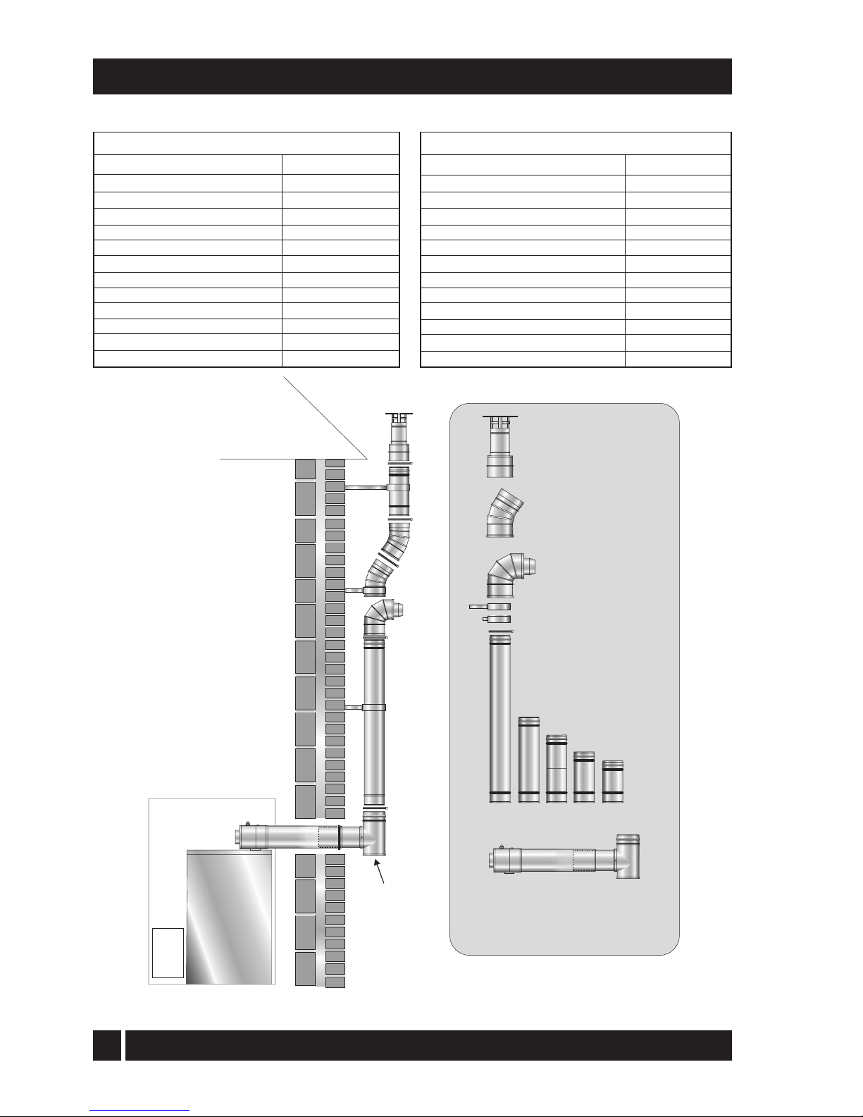
4 External balanced flue (iQE G-system)
Where it is not practical to use a low level
(iQE Y-system) or internal high level/vertical
(iQE W-system) balanced flue, the boiler
can be fitted with an external vertical/high
level flue (iQE G-system). See Fig. 10c.
T
he Starter kit fits to the boiler in the same
way as a low level balanced flue (iQE Ysystem) and the external Tee allows the
connection of a twin wall insulated flue
pipe and a combustion air inlet -providing
a room sealed flue system. The external
system can terminate at either high level or
vertically (above roof level) as required. See
Fig. 10c.
The minimum dimensions for locating the
t
erminal from building features (windows, doors,
etc.) are shown in Fig. 11.
If the
flue terminal is fitted less than 2 metres
above a surface to which people have access, the
terminal must be protected by a guard. The guard
must be fitted centrally over the flue terminal and
securely fixed to the wall.
The low level balanced flue (iQE Y-system) is
supplied with a stainless steel guard. This must
be fitted in all circumstances to prevent objects
from entering the flue outlet.
The
terminal must be positioned so as to avoid
products of combustion accumulating in
stagnant pockets around the buildings or
entering into buildings. Care should be taken
that the plume from condensed flue gases does
not cause a nuisance.
T
he following external flue (iQE G-system)
components are available from iQE.
iQE Horizon Internal Oil Boiler
4.8
Balanced flue options
Page 21
20
4 - GENERAL BOILER INFORMATION
Fig. 10c - External balanced flue (G-system)
G-System components
Item - for 15/26 models
Starter kit - standard
Sta
rter kit - short
150 mm extension
250 mm extension
450 mm extension
950 mm extension
195-270 mm adjustable
extension 45° elbow
High level terminal
Vertical terminal
Wall bracket - standard
Wall bracket - extended
Part No.
iQEG90
iQEG90S
iQEG90/150
iQEG90/250
iQEG90/450
iQEG90/950
iQEG90/250A
iQEG90/45EL
iQEG90HLT
iQEG90VT
iQEG90WBS
iQEG90WBE
Vertical Terminal Kit
iQEG90VT 15/26)
iQEG200VT (26/35)
O
45 Elbow Kit
iQEG95/45EL (15/26)
iQEG200/45EL (26/35)
Starter kit
iQEG90 (15/26)
iQEG200 (26/35)
iQEG90S short (15/26)
iQEG200S short (26/35)
High Level Terminal Kit
iQEG90HLT (15/26)
iQEG200HLT (26/35)
Extension Kits
Extended Wall Bracket
Wall bracket Locking band
Air
intake
DO NOT
OBSTRUCT
Components and Part Numbers
Typical
flue system
G-System components
Item - for 26/35 model
Starter kit - standard
Sta
rter kit - short
150 mm extension
250 mm extension
450 mm extension
950 mm extension
195-270 mm adjustable extension
45° elbow
High level terminal
Vertical terminal
Wall bracket - standard
Wall bracket - extended
Part No.
iQEG200
iQEG200S
iQEG200/150
iQEG200/250
iQEG200/450
iQEG200/950
iQEG200/250A
iQEG200/45EL
iQEG200HLT
iQEG200VT
iQEG200WBS
iQEG200WBE
iQE Horizon Internal Oil Boiler
Page 22

21
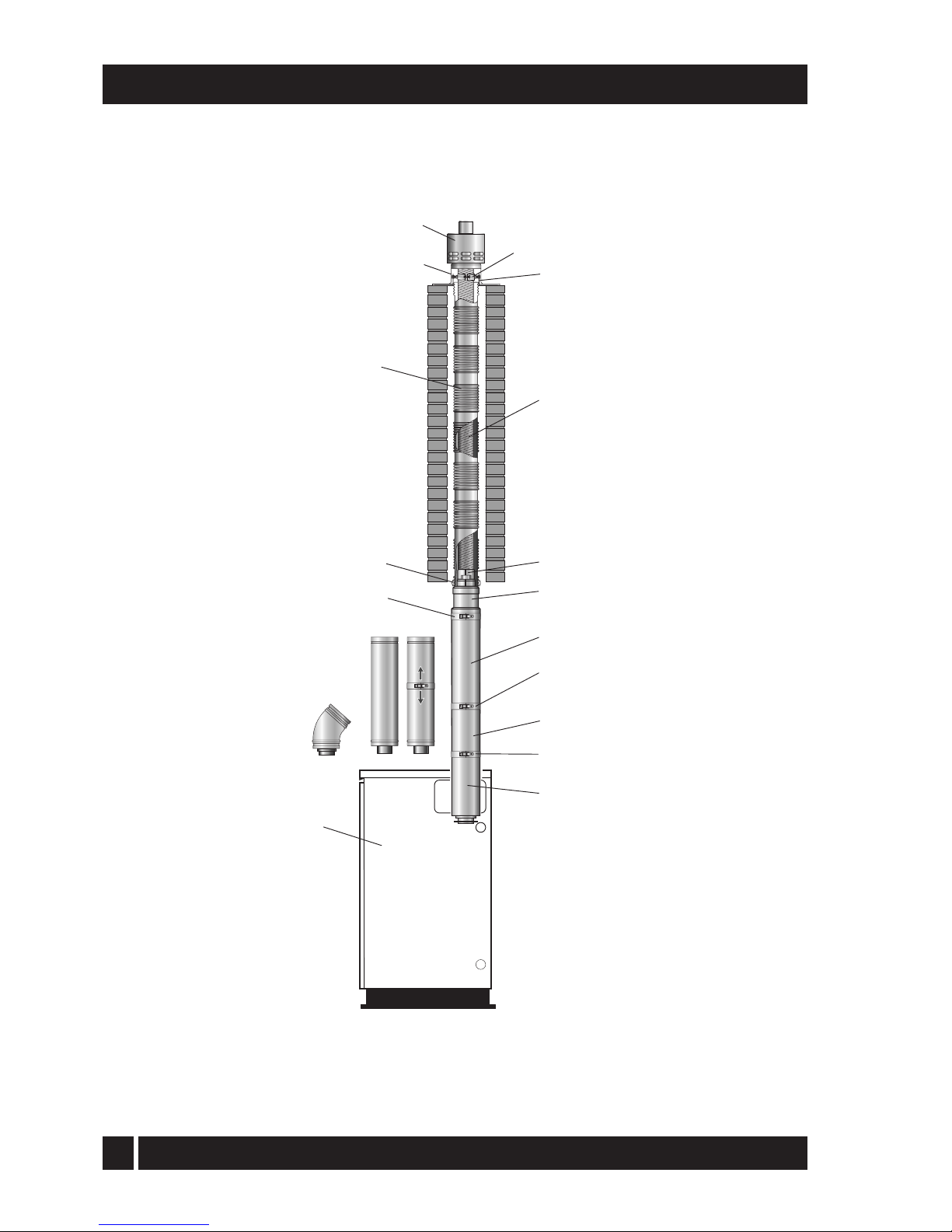
5.
F
lexible vertical balanced flue (iQE R-system)
This is a flexible vertical balanced flue
system (for the 15/26 models only)
designed to be fitted inside an existing
masonry chimney. See Fig. 10d. It basically
consists of three sections:
Concentric white painted flue pipe
connected to the boiler
Vertical concentric flexible flue (flexible
stainless steel flue liner inside a flexible
plastic air inlet liner) Terminal assembly for
chimney top mounting
The flue pipe seals are factory fitted and
must be lubricated with the lubricant
supplied before assembly.
Th
e iQE R-system is supplied as a separate kit.
Flue extensions and 45° elbows from the
White system may be used to extend the flue
between the boiler and the flexible section of
the system.
The maximum vertical straight length of flue,
from the top of the boiler to the top of the
terminal, is 20 metres using no more
than four 45° elbows. Deduct 1 metre
of straight flue length for every elbow used.
Note: If the flexible liners have to pass
around an offset inside the chimney
deduct 2 metres of straight flue length to
compensate for this.
4 - GENERAL BOILER INFORMATION
F
lue extensions cannot be cut, use adjustable
extensions where required.
Three types of locking band are supplied
with the kit. The first type is painted white
and is for connecting flue sections that butt
together (2 of this type of locking band are
supplied). The second type, also painted
white, is to cover the joint on the adjustable
(telescopic) section.
Note: The locking band for the adjustable
section is labelled for easy identification.
The third locking band is plastic and
supplied in two halves. This is to secure the
plastic flexible liner to the adapter.
The flue kit includes a Black coated
terminal with upstand and is designed to
be fixed (using the screws provided) to the
top of a masonry chimney.
The flue system may be offset using 45°
elbows (ref. iQE90EX45ELB). No more
than a maximum of four elbows should be
used per system.
iQE Horizon Internal Oil Boiler
Page 23
22
Boiler
Outer plastic liner
Inner stainless steel liner
Terminal
Terminal upstand
Top plate
Support clamp
Connector
Rigid/flexible adaptor
Starter section
Telescopic flue (lower)
Telescopic flue (upper)
Locking band for
adjustable joint section
Plastic locking
band Locking
band
Locking band
Elbow, extension
and adjustable extension
from W-system
F
ig. 10d - Flexible vertical balanced flue (iQE R-system) up to 26kW only
4 - GENERAL BOILER INFORMATION
iQE Horizon Internal Oil Boiler
Page 24
23
4 - GENERAL BOILER INFORMATION
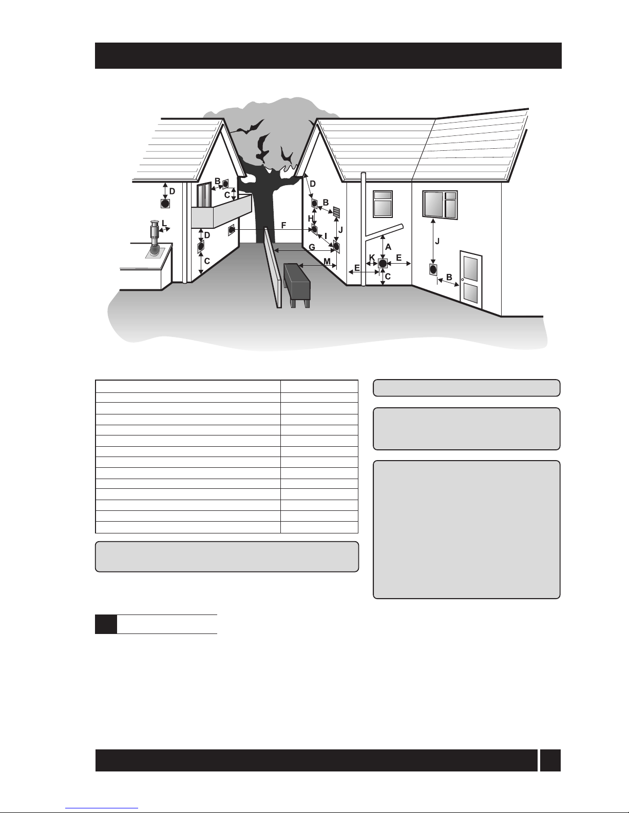
Fig. 11 - Clearances for Balanced flues
Notes: * 75 mm with protection.
** Only applies if one or both terminals are balanced flues.
Distances measured to rim of terminal.
Clearances recommended by iQE in
accordance with British Standards and
Building Regulations.
Terminal position
A Below a gutter or sanitary pipework
B Horizontal from an opening, air brick or window
C Above ground or balcony level
D Below eaves or balcony
E From an internal or external corner
F From a terminal facing the terminal
G From a surface facing the terminal
H Vertical from terminals on the same wall
I Horizontal from terminals on the same wall
J Below an opening, air brick, window etc.
K From vertical sanitary pipework
L Vertical flue from a wall
M From an oil storage tank
Min. distance (mm)
* 600
600
300
*600
300
1200
600
1500
**750
600
300
750
1800
Notes:1 An opening means an openable
element, such as an openable
window, or
a permanent opening
such as a permanently open air
vent.
2 Notwithstanding the dimensions
given, a terminal should be at least
300 mm from combustible
material, e.g. a window frame.
3 A way of providing protection of
combustible material would be to
fit a heat shield at least 750 mm
wide.
Where the frost thermostat is installed outside the
house (to protect a boiler installed in an external
boiler room or garage) or in an attic, it is
recommended that it be used in conjunction with a
pipe thermostat to avoid unnecessary and wasteful
overheating of the property. The pipe thermostat
should be located on the boiler return pipe, and set to
operate at 25° C. Refer to Section 10 for connection
details.
For additional protection of either the entire heating
sy
stem, or the boiler and localised pipework, it is
recommended that a frost thermostat be installed.
Refer to Section 10 for connection details.
To protect the heating system, the frost thermostat
should be sited within the house in such a place that it
can detect any rise and fall in the ambient air
temperature, i.e. in a room with a radiator.
The Installer must e
nsure that the terminal does not
cause a
nuisance.
iQE Horizon Internal Oil Boiler
4.9
Frost protection
Page 25
24
4 - GENERAL BOILER INFORMATION
1 The boiler must stand on a surface that is firm and
level. It does not require a special hearth as the
temperature of the boiler base is less than 50° C.
2 Sufficient clearance must be allowed at the front of the
boiler to remove the burner and baffles for servicing.
3 Once the boiler has been installed, a permanent
workt
op may be fitted over it as access to the top
of the boiler is no longer required after installation.
Sealed system kit fitted - A removable
section of worktop above the boiler is
required to provide access for servicing.
IMPORTANT: All pipes to be fitted into the push-fit connectors provided should be cut using a pipe slicer or pipe
cutter to leave the pipe ends with a slight radius and free from any burrs or sharp edges.
Pipes to be used with these fittings should not be cut square using a hacksaw.
All models
To avoid the danger of dirt and foreign matter entering the boiler the complete heating system should
be thoroughly flushed out - before the boiler is connected and then again after the system has been
heated and is still hot. This is especially important where the boiler is used on an old system.
For optimum performance after installation, this boil
er and its associated central heating system must be flushed in
accordance with the guidelines given in BS 7593:1992 'Treatment of water in domestic hot water central heating
systems'.
This must involve the use of a proprietary cleaner, such as Sentinel X300 or X400. Full instructions are
supplied with the products, but for immediate information, please contact Sentinel on 01928 588330.
For Long term protection against corrosion and scale, after flushing, it is recommended that an
inhibitor such as Sentinel X100 is dosed in accordance with the guidelines given in BS 7593:1992.
Failure to implement the guidelines will invalidate the warranty.
A drain cock i
s fitted at the bottom on the front of the boiler to allow the heating system to be drained.
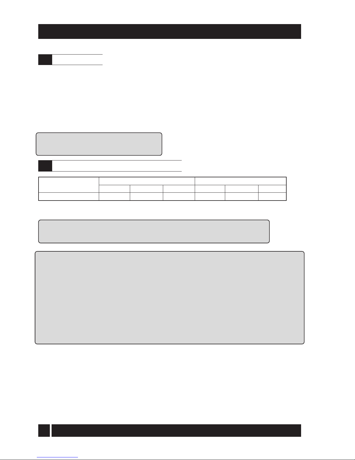
15/26, 26/35 Internal bo
ilers
22 mm pipe Tectite elbow in fittings kit 22 mm pipe
Return connection
Fitting
Compression fitted
Size SizeFitting Supplied
Supplied
Boiler model
Flow connection
iQE Horizon Internal Oil Boiler
4.10
Boiler location
4.11
Water connections - all models See Fig. 12
Page 26
25
4 - GENERAL BOILER INFORMATION
See Fig. 13
iQE sealed system kits, incorporating circulating
pu
mps are available. See Section 6.6 and 6.7.
1 The boiler is only suitable for use with a sealed system
complying with the requirements of BS
5449. The maximum temperature of the
central heating water is 80°C.
2 The system must be provided with the following
i
tems:-
a
Diaphragm
expansion vessel complying with
BS 4814.
b Pressure gauge.
c Safety valve.
d Approved method for filling the system.
Refer to BS 7074:1 for further guidance.
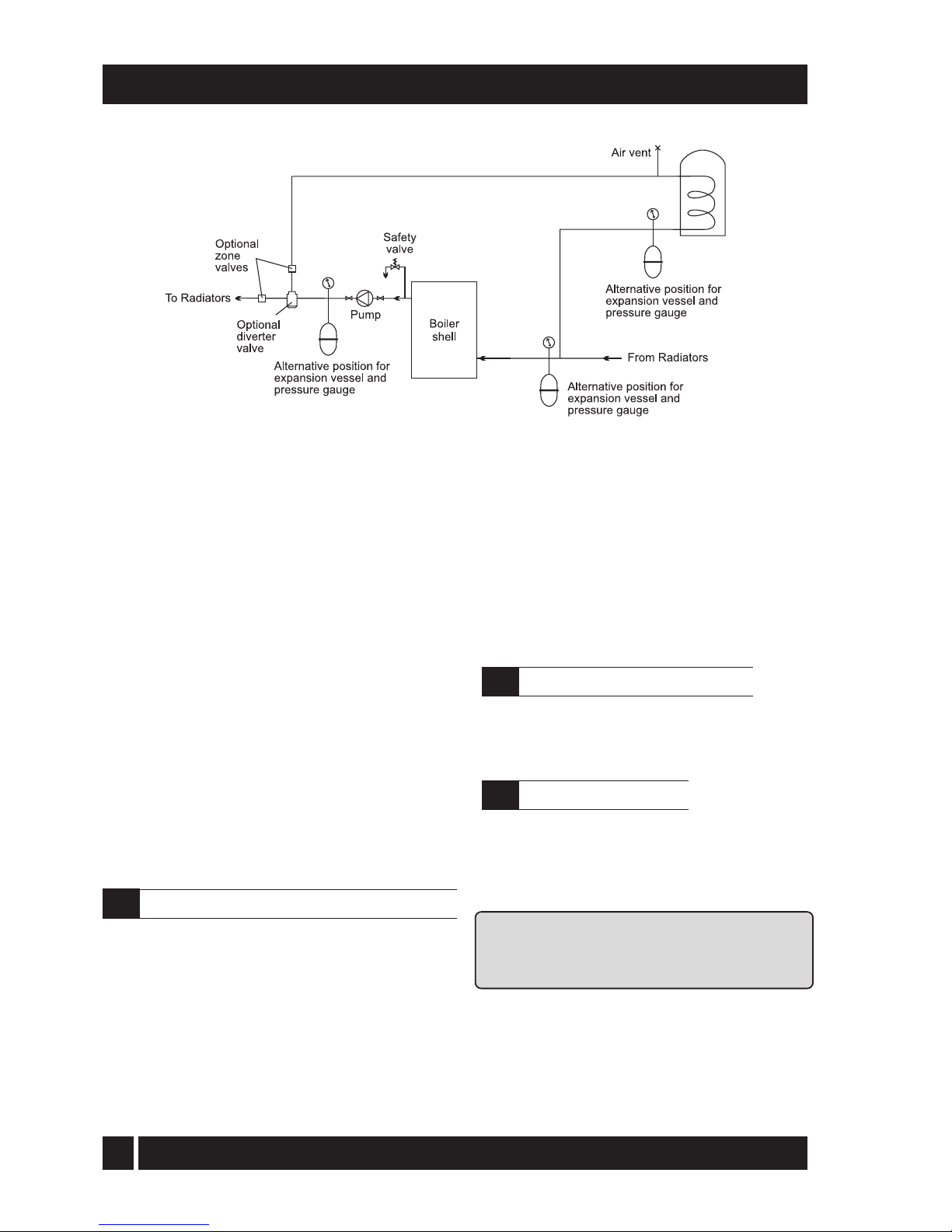
Fig. 12 - Water connections and the
rmostat phial positions
3 The expansion vessel can be fitted in either the
return or flow pipework in any of the
recommended positions as shown in Fig. 12. To
reduce the operating temperature of the
expansion vessel diaphragm, position it below
the pipe to which it is connected. The
expansion vessel may be positioned away
from the system, providing the connecting
pipe is not less than 13 mm diameter.
4 The pressure gauge should have an operating
range of 0 to 4 bar.
5 The safety valve, set to operate at 2.5 bar, should
be fitted in the flow pipework near to the boiler.
The pipework between the safety valve and
boiler must
be unrestricted, i.e. no valves. The
safety valve should be connected to a
discharge pipe which will allow the discharge to
be seen, but cannot cause injury to persons or
property.
iQE 15/26
Heating flow Heating return
Thermostat phials
Heating return
Heating flow
iQE 26/35
Thermostat phials
iQE Horizon Internal Oil Boiler
4.12
Sealed system kit
Page 27
26
4 - GENERAL BOILER INFORMATION
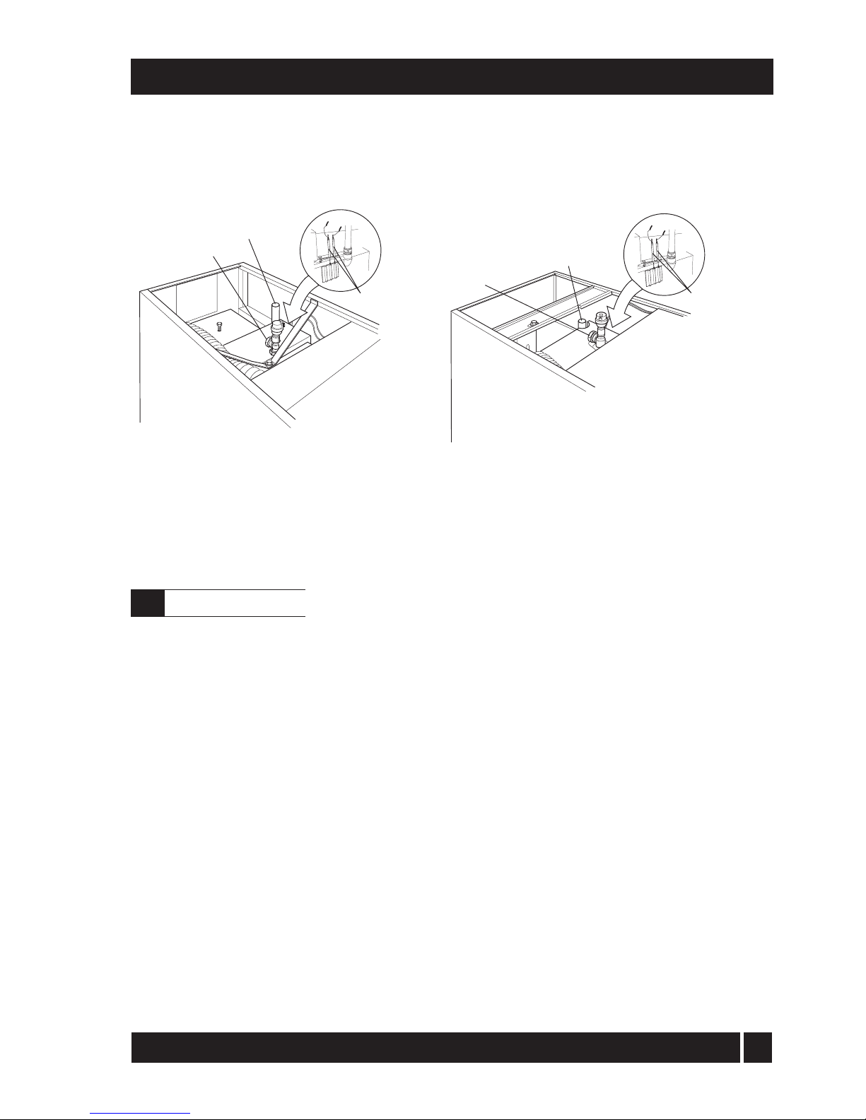
Fig. 13 - Sealed system
6 Provision should be made to replace water lost
from the system. This can be done manually
(where allowed
by the local water undertaking)
using an approved filling loop arrangement
incorporating a double check valve assembly.
7 An automatic air vent should be fitted to the
highest point of the system.
8 The system design pressure (cold) should be
between 0.5 and 1.0 bar. This pressure is
equivalent to the maximum static head in bar +
0.3 (1 bar = 10.2 metres of water).
9 All fittings used in the system must be able to
withstand pressures up to 3 bar.
10 Radiator valves must comply with the requirements
of BS 2767(10):1972.
11 One or more drain taps (to BS 2879) must be used
to allow the system to be completely drained.
12 For proprietary expansion vessel/valve/gauge
packs, refer to the manufacturers instructions
for the correct location on the heating system.
1 A 15 mm discharge pipe must be connected to
the safety valve outlet connection. The pipework
between the safety valve and the boiler must be
unrestricted, i.e. no valves. The discharge pipe
should be run to the outside of the building and
terminate so that it cannot cause injury to
persons or property.
2 A 15 mm double check valve ballofix type valve is
provided on the flexible filling loop hose for
connection of the cold mains supply to the heating
system. The cold mains supply should terminate
inside the boiler casing.
3 The expansion vessel is connected via a flexible
hose to allow it to be moved to gain access to
the baffle cleaning cover. When replacing the
vessel, care should be taken to ensure that the
flexible connecting hose is not twisted.
On underfl
oor systems it is essential that the return
temperature must be maintained above 40° C to
prevent internal corrosion of the boiler water jacket.
General - iQE Horizon boilers are
compatible with
both copper and plastic pipe. Where plastic pipe is
used it must be of the oxygen barrier type and be of
the correct class (to BS 7291:Part 1:1990) for the
application concerned.
IMPO
RTANT: The first metre of pipework
connected to both the heating flow and return
connections of the boiler must be made in copper
on all types of system - sealed or open-vented.
Sealed
systems - If plastic pipe is to be used, the
installer must check with the plastic pipe
manufacturer that the pipe to be used is suitable
for the temperature and pressures concerned.
Pipe must be Class S to BS 7291: Part 1:1990.
iQE Horizon Internal Oil Boiler
4.13
Water connections - Sealed system kit
4.14
Underfloor heating systems
4.15
Pipework materials
Page 28
27
4 - GENERAL BOILER INFORMATION
When in condensing mode the iQE boilers
produce condensate
from the water vapour in
the flue gases. This condensate is slightly
acidic with a ph value of around 3 (similar to
vinegar). Provision must be made for the safe
and effective disposal of this condensate.
Condensate can be disposed of using one
of the following
methods of connection:
Internal connection (preferred option)
•
into an internal do
mestic waste system
(from kitchen
sink, washing machine, etc.)
•
directly into the soil stack
External connection
• into an external soil stack
• into an external drain or gulley
• into a rainwater hopper (that is part of a
combined system where sewer carries
both rainwater and foul water)
• purpose made soakaway
All condensate disposal pipes MUST be
fitted with a trap - whether they are
connected internally or externally to a
domestic waste system/soil stack or run
externally to a gully, hopper or soakaway.
Connections into a rainwater hopper, external
d
rain or gulley should be terminated inside the
hopper/drain/gulley below the grid level but
above the water level.
Condensate disposal pipes should not be
connected directly into rainwater downpipes or
to waste/soil systems
connected to septic
tanks.
Condensate should not be discharged into 'grey
water' syst
ems that re-use water used in the
home (not including water from toilets).
It should be noted that connection of a
condensate pipe to the drain may be subject to
local Building Control requirements.
Condensate disposal pipework must be plastic
(p
lastic waste or overflow pipe is suitable).
IMPORTANT: Copper or steel pipe is NOT
suitable and MUST NOT be used.
Condensate disposal pipes should have a
minimum 'nominal' diameter of 22 mm (¾") e.g. use 21.5 mm OD polypropylene overflow
pipe.
Condensate disposal pipes must be fitted
with a fall (away from the boiler) of at least
2.5° (~45 mm fall per metre run).
5 - CONDENSATE DISPOSAL
The sy
stem should incorporate a low-pressure
switch to shut off power to the boiler if the system
pressure drops below 0.2 bar. A suitable low
pressure switch kit is available to purchase from iQE
Part No. iQE CF15/35
Underfloor systems - Plastic pipe may be used on
Underfloor systems where th
e plastic pipe
is fitted
after the thermostatic mixing valve. Copper tube
m
ust be used for at least the first metre of flow and
return primary pipework between the boiler and
the underfloor mixing/blending valves.
iQE Horizon Internal Oil Boiler
5.1
General requirements
5.3
Pipework
5.2
Connections
Page 29
28
Note: Where it is not possible for the pipe to fall
towards the point of discharge - either internally
into a waste system or externally to a gulley (e.g.
for boilers installed in a basement), it will be
necessary to use a condensate pump.
C
ondensate disposal pipes should be kept as short
as p
ossible and the number of bends kept to a
minimum.
Pipes should be adequately fixed to prevent
sa
gging, i.e. at no more than 0.5 metre intervals.
External pipework
Ideally, external pipework, or pipework in
unheated areas, should be avoided. If
unavoidable, external pipework should be kept as
short as possible (less than 3 metres) and 32 mm
waste pipe used to minimise the risk of ice
blocking the pipe in freezing conditions.
The number of bends, fittings and joints on
external pipes should be kept to a minimum to
reduce the risk of trapping condensate.
Note: For boiler installed in an unheated area
such as an outhouse or garage, all condensate
pipework should be considered as an ‘external’.
5 - CONDENSATE DISPOSAL
To keep external pipework to a minimum, locate
the soakaway as close as possible to the boiler
but ensure it is
at least 1 metre from building
foundations and away from other services, e.g.
gas, electricity, etc.
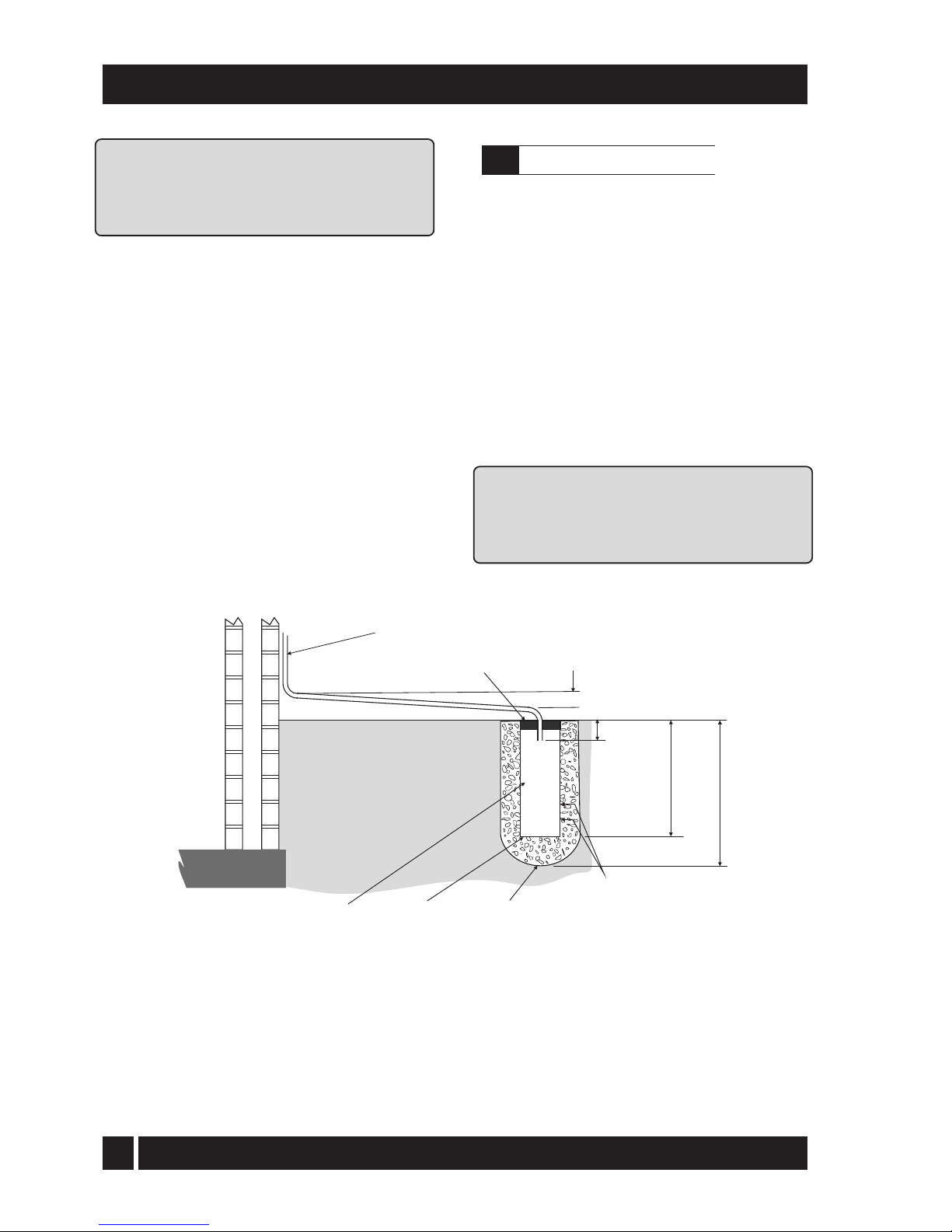
The condensate pipe may be run above or below
ground level and can enter either the top or side
of the soakaway tube. Refer to Fig.14.
Ensure t
hat the drainage holes in the soakaway
tube face away from the building.
Backfill both the soakaway tube, and the hole
around it,
with 10 mm limestone chippings.
Only use a soakaway where the soil is porous and
drains easily. D
o not use in clay soils or where the
soil is poorly drained.
WARNING: Any damage due to condensate
backing up into the boiler due to a high water
table, in
the case of a soakaway, or flooded
drains when the condensate disposal is via a
gulley or soil stack, is not covered by the iQE
product warranty.
Fig. 14 - Purpose made condensate soakaway
Ground level
32 mm waste pipe external to the building
O
2.5 f
all
25 mm
300 mm
400 mm
min.
Cement seal
100 mm
plastic
tube
Sealed
end
Backfill with 10
mm limestone
chippings
iQE Horizon Internal Oil Boiler
5.4
Condensate soakaway
Two rows of 3 x 12mm
holes at 25 mm centres and
50 mm from the bottom of
the tube. Holes facing away
from the property.
Page 30
29
5 - CONDENSATE DISPOSAL
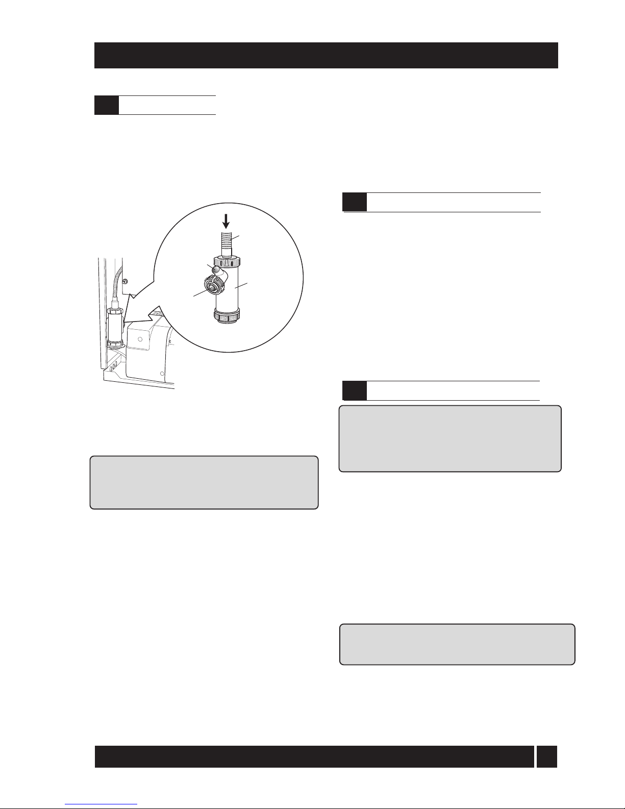
iQE boilers are supplied with a factory-fitted
condensate trap to provide the required 75 mm
water seal in the condensate discharge pipe from
the boiler.
This trap incorporates a float (which will create a
seal when the trap is empty) and an overflow
warning outlet (fitted with a plastic sealing cap),
See Fig. 15.
Care should be taken when siting the trap such
that the overflow outlet is readily visible and that
any condensate overflowing from the outlet
cannot cause either a hazard to persons or
damage to surrounding property or equipment.
The condensate trap outlet is at an angle of 48°
below the horizontal. This is to automatically give
a 3° fall on any 'horizontal' runs of condensate
disposal pipe. Refer to Fig.15.
The outlet of the trap will accept 21.5 mm to 23
mm OD Polypropylene overflow pipe for the
condensate discharge pipe.
This discharge pipe can exit through the left
hand side of the boiler through one of pre-cut
'knock-outs' in the casing panel (see to Fig. 1).
Push out the 'knock-out' from the required hole
taking care not to distort the side panel.
The trap MUST be checked at regular intervals
(e.g. on every annual service) and cleaned as
necessary to ensure that it is clear and able to
operate.
Note: The bottom bowl is sealed to the trap
body and cannot be removed.
To inspect and clean the trap:
1 Disconnect flexible condensate hose from inlet
connector.
2 Unscrew
the inlet connection nut.
3 Remove the inlet connector and nut from trap.
4 Remove trap from bracket.
5 Remove float from trap – clean if necessary.
6 Inspect inside
of trap and clean as necessary.
7 Re-assemble trap, re-fit to boiler and re-connect
flexible hose. Ensure that hose is fully pushed
onto the trap inlet connector.
IMPORTANT: Failure
to regularly check and clean the
condensate trap may result in damage to the boiler
and will not be covered by the Product Warranty.
Fig. 15 - Condensate trap
The
trap is factory-fitted inside the boiler casing
(mounted on the inside of the left side panel) in an
accessible position to allow for routine maintenance.
Note: If required, this condensate trap may be relocated outside the boiler casing. Refer to
procedure given in 'external condensate trap'.
This procedure MUST be carried out before the
boiler is installed.
A flex
ible hose connects the outlet of the
condensing heat exchanger to the trap inlet. Ensure
the straight connector on the hose is fully pushed
onto the 'top hat' inlet connector of the trap.
W
ith the trap fi
tted inside the boiler casing, the
sealing cap MUST be f
itted. If the trap is re-located
outside the boiler then the following applies:
If connecting the condensate discharge (either
internally or externally) into a waste system or
soil stack - the sealing cap MUST be fitted in the
trap outlet.
On external discharge systems to a hopper, gully
or soakaway, the sealing cap should be removed
from the trap outlet.
If there is any discharge of condensate from the
overflow outlet, this could indicate a blockage
(possibly due to freezing). Turn off the boiler and
investigate the cause. If necessary contact your
service engineer for assistance.
Condensate
trap
Condensate
outlet to
drain
Overflow
warning
outlet
(with cap)
Condensate
drain pipe
from boiler
iQE Horizon Internal Oil Boiler
5.6
Condensate disposal pipework
5.6
Inspection and cleaning of trap
5.5
Condensate trap
Page 31
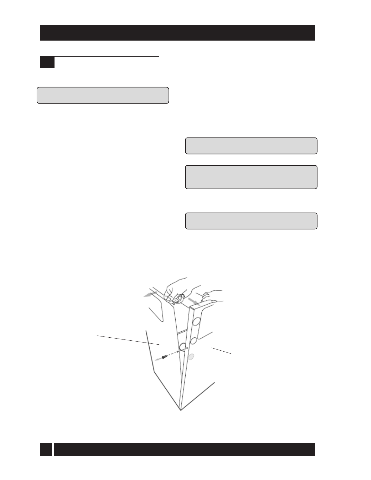
30
5 - CONDENSATE DISPOSAL
To re-locate the factory-fitted trap outside the
boiler casing,
use the following procedure:
Note: This procedure must be carried out before
the boiler is installed.
1 Remove the top casing panel(s) from the boiler.
2 Unscrew and remove the screws fastening the left
side panel to the rear casing panel of the boiler.
3 Carefully separate the left side and rear panels
just enough to gain access to the condensate
outlet on the left rear of the condensing heat
exchanger (see Fig.16).
4 Push out pre-cut 'knock-out' from the condensate
outlet hole in the rear of left side casing panel.
5 Remove the right angle end of the flexible
cond
ensate discharge hose from the outlet
connection on the condensing heat exchanger.
6 From the front of boiler, remove the straight
connector end of the flexible hose from the
top of the condensate trap.
7 Reverse the flexible hose and pass the
straight connector end through the new hole
in the left hand casing panel. Push the straight
connector firmly onto the condensate outlet
connection of the condensing heat exchanger
- push on at least 20 mm.
8 Refit the left hand casing panel to the rear panel
using the reverse procedure, ensuring all fixing
screws are used.
9 Remove the trap from the mounting bracket.
10 Unscrew and remove the trap mounting bracket
from the left side panel.
11 Fix the trap mounting bracket to the wall adjacent
to the boiler in the required position.
Note: The top of the trap must be below the
condensate connection on the boiler.
12 Re-fit the trap to the mounting bracket.
The mounting bracket supplied with the trap
MUST be used - the trap should NOT be
supported by the condensate pipework only.
13 Connect the flexible condensate hose to the trap,
pushing the right angle hose connector onto
the trap inlet connection.
IMPORTANT: The flexible
hose must fall continuously
from the outlet to the top of the trap.
Fig. 16 - Remove the condensate trap
Rear panel
Left hand side panel
iQE Horizon Internal Oil Boiler
5.7
External condensate trap fitting
Page 32
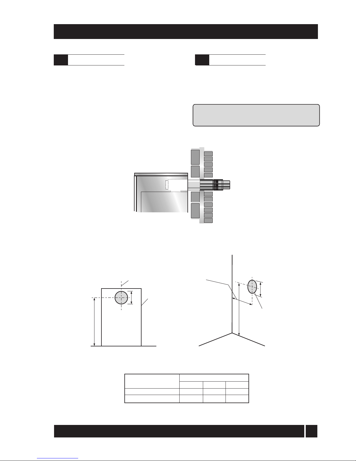
31
1 Carefully remove the packaging from the
boiler and remove it from the transit pallet.
2 Pull the front panel forward at the top to
disengage the fixing clips then lift it up
and off the boiler. Remove the literature
packs. Give the User Information pack to
the householder.
3 Lift off the case top panel(s) and remove the
water connecting fittings.
6 - BOILER INSTALLATION
See Fig. 17 and 17a
If the boiler
is to be used with a low level
balanced flue (iQE Y-system) make the hole
in the wall for the flue as shown in Fig. 17.
Note: Dimension
B given in Fig. 17a includes
an extra 10 mm over the size of the terminal
to provide clearance for fitting.
Fig. 17a - Low level balanced flue (
iQE
Y-System) and Starter kit (
iQE
G-System)
Fig. 17 - Low level balanced flue
Sidewall
Rearwall
Note: This dimension is given with
the boiler pushed back against
the rear wall. Any clearances
must be added to it.
Boiler
centre line
Outline
of boiler
Rear exit
Side exit
C
C
A
A
B
15/26
26/35
C
768
780
Dimension (mm)
Model
A dia
127
162
B
115
115
iQE Horizon Internal Oil Boiler
6.2
Prepare the wall
6.1
Unpack the boiler
Hole to be
cut in wall
Page 33
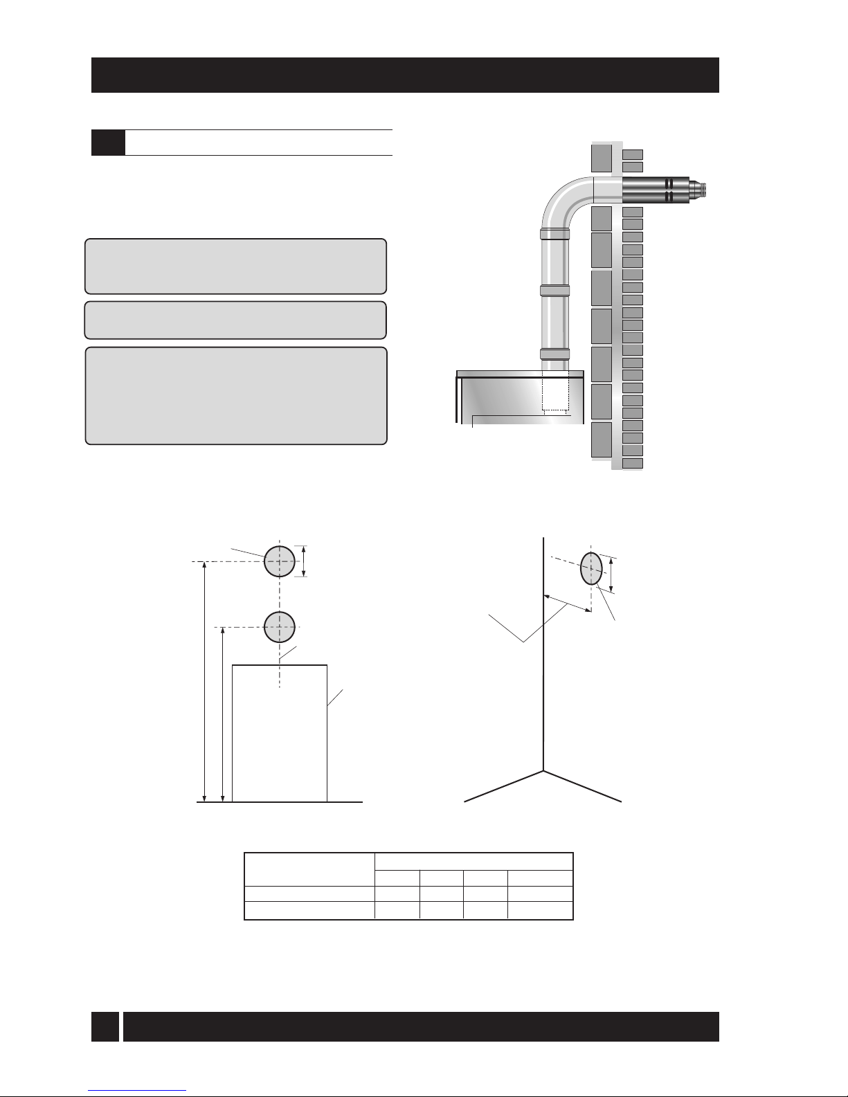
32
6 - BOILER INSTALLATION
Fig. 18a - High level balanced flue (
iQE
W-system)
Fig. 18 - H
igh level balanced flue
*Dimension C for Starter section and elbow/terminal only
See Fig. 18 and 18a
If the boiler is to be used with the high level
balanced flue (iQE W-system) make the hole
in the wall as shown in Fig. 18a.
Note
: Dimension B given in Fig. 18a includes an
extra 10 mm over the size of the terminal to
provide clearance for fitting.
Fitting instructions for the high level balanced flue and
vert
ical balanced flue are supplied with the flue kits.
Adjustable sections:
The adjustable extensions
are telescopic. The wall terminal section is
adjustable and is suitable for a wall thickness of
215 mm to 450 mm. Simply adjust to the required
length using a twisting motion. The outer pipes
must overlap by a minimum of 25 mm.
Sidewall
Rearwall
Note: This dimension is given with
the boiler pushed back
against the rear wall. Any
clearances must be added
to it.
Hole tobe
cut in wall
Boiler
centre line
Outline
of boiler
Rear exit
Side exit
Standard kit with no extensions
D
C
A
A
B
15/26
26/35
D
1715 - 2115
1700 - 2020
Dimension
(mm) Model
175
200
115
115
A dia B C
1215*
1280*
iQE Horizon Internal Oil Boiler
6.3
High level and vertical balanced flue
Hole to be
cut in wall
Page 34
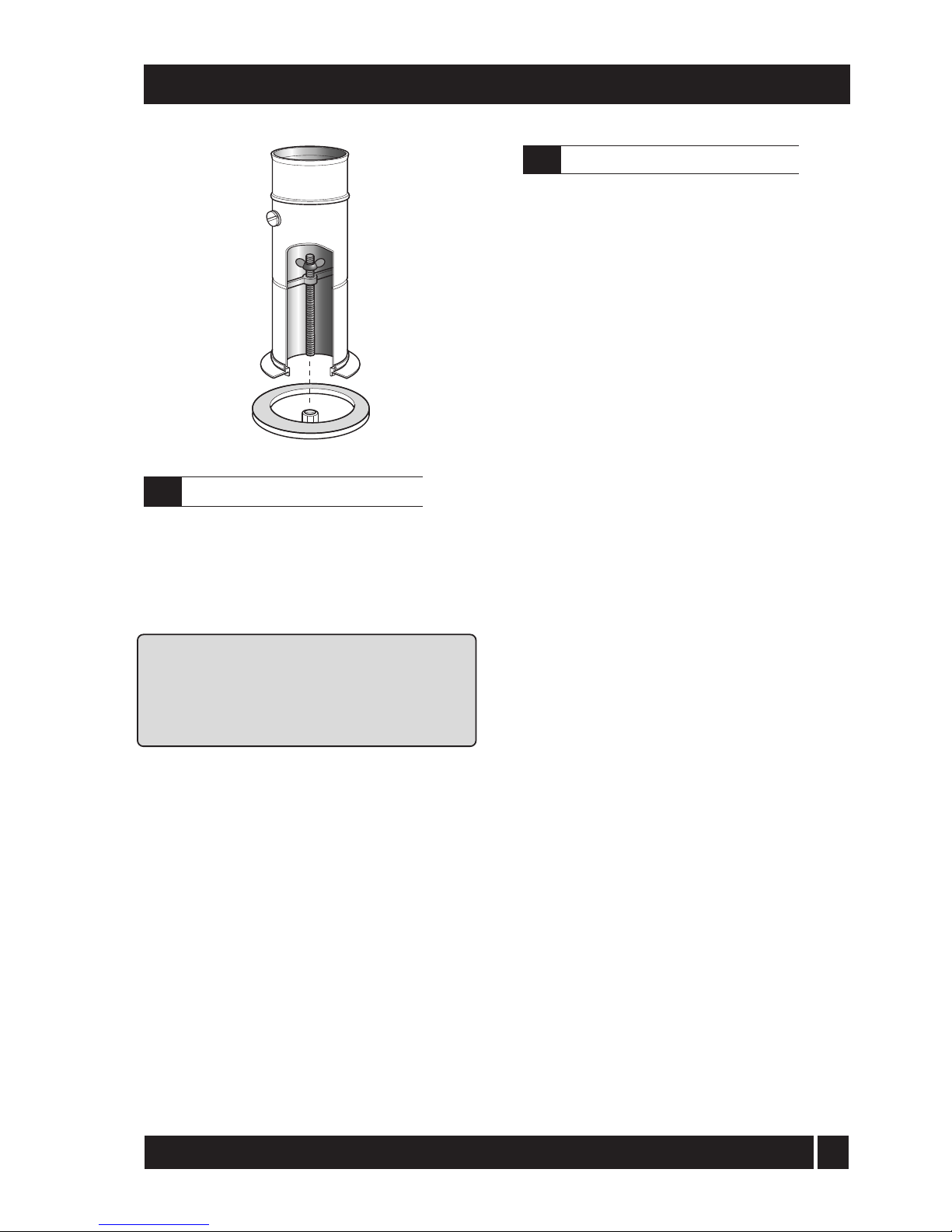
33
Refer to Section 4.11 and 4.12 and Fig. 12. for the size,
type and position of the connections.
The Flow and Return pipework can be routed to
either side of the boiler, dependant on the type
and direction of the flue system used.
For condensate disposal pipework refer to Section 5.
IMPORTANT: All pipes to be fitted into the pushfit connectors provided should be cut using a
pipe slicer or pipe cutter - to leave the pipe ends
with a slight radius and free from any burrs or
sharp edges. Pipes to be used with these fittings
should not be cut square using a hacksaw.
Pipe entry/exit holes in case
All models have holes to enable the pipework to
exit the boiler casing. On the 15/21 and 21/26
models these holes are pre-cut knock-outs
located at the rear of both side panels and on the
26/35 model these pre-cut holes are in the
removable flue outlet cover plates.
Push out the 'knock-out' from the required holes,
taking care not to distort the side panel.
If access will be restricted, make any connections
to the boiler before placing it in its final position.
If using a balanced flue system - Install the
balanced flue system before connecting the
heating system pipework to the boiler. Once the
flue system is fitted then complete the water
connections and fill the heating system.
If using a conventional flue system - Complete
the water connections and fill the heating system.
Check all connections for leaks and rectify as
necessary. If the iQE sealed system kit is fitted,
refer to Section 6.6 for details on filling and
venting the sealed heating system.
6 - BOILER INSTALLATION
1. Lift off upper rear casing panel.
2.
R
emove the insulation from the underside of
the p
a
nel (do not discard it). Carefully press
out the pre-cut flue opening in the top panel.
3.
Unscrew the protective covers from the studs on
the flue
dress panel supplied in the literature
pack. Place the dress panel in position in the rear
casing top panel and secure in place using the
nuts and washers previously removed.
4.
Re-fit the insulation to the panel with the foil
surf
a
ce facing outwards. With a sharp knife cut
around the edge of the round opening in the
dress plate to leave a round hole through the
insul
ation for the flue.
5.
If th
e iQE O-system is being used –follow
the instructions supplied with the flue kit.
6.
If the iQE G-system (100 mm rigid twin-wall
flue) is to be fitted to the boiler then the iQE
adaptor kit (Ref. iQE CF15/35) must be used –
refer to Section 4.1. To fit the adaptor kit,
proceed as follows.
7.
Fully screw the length of threaded studding
(provided in the kit) into the nut located in
the centre of the boiler flue outlet.
8.
Fit the boiler connector (from the CF adaptor
kit) over the
threaded studding. Position flange
on to the neoprene gasket around the boiler
flue outlet, ensuring that small spigot on the
base of the connector is located in the hole in
the centre of the neoprene gasket and that end
of studding passes through the hole in the of
the spacer bracket. Fit washer and wing nut
provided onto end of threaded studding and
secure connector in position by tightening
down on wing nut – as shown in Fig. 21.
9. Re-fit the rear top casing panel to the boiler
–fitting it over the boiler connector.
10.
Fit th
e flue adaptor (from the adaptor kit) into
the boiler connector. Note lubricate the seal on
the adaptor using the lubricant provided
before attempting to fit the flue adaptor.
11.
Fit th
e first section of flue into the flue adaptor
and secure using the clamp band provided.
12. Assemble the remainder of the flue system
as required, lubricating the seal on each
component before fitting.
Fig. 19 - Boiler flue connector
iQE Horizon Internal Oil Boiler
6.4
Make the water connections
6.5
Connect a conventional flue
Page 35
34
6 - BOILER INSTALLATION
1 The kit includes the following items:
Pressu
re relief valve and automatic air vent assembly
22 mm push-fit elbow
12-litre expansion vessel with flexible hose and
sealing washer
Filling loop kit - including pressure gauge mounted
on shut-off valve
6 m head circulating pump with 22 mm gate type
valves
15 mm copper pressure relief valve discharge pipe ½"
BSP black iron Tee
Pump support bracket – with screw, nut & washer
2 Unscrew the burner securing nut and remove the
burner from the boiler.
3 Remove the ½" BSP black iron plug from the front
of the boiler waterway, using a 3/8" drive
socket wrench.
4 Remove the compression nut and olive from the
end of the filling loop shut-off valve. Fit the ½"
BSP straight end of the shut-off valve into one
side of the black iron tee, using a suitable
thread sealant (not supplied).
5 Fit the male thread of the black iron Tee into the
tapping on the front of the waterway using a
suitable thread sealant. Tighten until Tee (and
shut-off valve) is horizontal.
6 Connect the flexible expansion vessel hose to the
remaining connection on the black iron Tee.
7 Position the 12-litre expansion vessel on the front of
the boiler combustion door locating the vessel
bracket into cut-out in the front of the
combustion door.
Note: on 15/26 model press on the pre-cut
section in the centre of the door to form the
cut-out for the bracket.
8 Fit the ¾" BSP connection of the flexible expansion
vessel hose to the vessel using the black
rubber washer supplied
and tighten the nut.
9 Fit the pump support bracket to the vertical plate
on top of the boiler shell. Fasten in place using
the scre
w, nut and washer provided.
10 Push the 22 mm push-fit elbow onto the boiler flow
connection.
11 Push the automatic air vent/pressure relief valve
assembly into the push-fit elbow.
12 Fit both 22 mm pump valves to the circulating
pump using the sealing washers supplied.
13 Fit the pump assembly to the automatic air vent/
pressure relief valve assembly ensuring that
the pump shaft is horizontal, the pump motor
is facing towards the front of the boiler and
the body is resting on the pump support
bracket. The flow arrow on the body of the
pump must face in the direction of flow away
from the boiler connection.
14 Fit the pressure relief valve discharge pipe to the
pressure relief valve using the nut and olive
supplied. Route the discharge pipe through
the slot in the base of the right hand side
panel. Push the panel insulation back to
expose the slot.
15 The circulating pump may be wired into the boiler
control panel if required. Refer to Section 10.
16 Re-fit the burner and tighten the fixing nut to secure.
17 The filling loop should be connected, via the
double check valve, to a 15mm cold water
supply pipe from the mains at a convenient
position inside the boiler.
The expansion vessel fitted, is supplied with a charge
pressure of 1.0 bar (equivalent to a max. static head of
10.2 metres). The charge pressure must not be less
than the actual static head at the point of connection.
Do not pressurise the vessel above 1.5 bar.
The air pressure in the vessel must be checked annually.
The c
entral heating system volume, using the expansion
vessel as supplied, must not exceed the recommended
volumes. If the system volume is greater, an extra
e
xpansion vessel (complying with BS 4841) must be
fitted as close as possible to the central heating return
connection on the boiler. The charge pressure of the extra
vess
el must be the same as the vessel fitted in the boiler.
Refer to BS 7074:1 for further guidance.
The air charge pressure may be checked using a
tyre pressure gauge on the expansion vessel
Schraeder valve. The vessel may be re-pressurised
using a suitable pump. When checking the air
pressure the water in the heating system must be
cold and the system pressure reduced to zero.
It is recomm
end that the boiler should be
connected to a switched mains power supply from
a programmer or control system. Refer to Sections
10 for typical control system wiring diagrams.
iQE Horizon Internal Oil Boiler
6.7
Sealed system expansion vessel pressure
6.6
Sealed system kit - 15/26 and 26/35
Page 36

35
6 - BOILER INSTALLATION
1 Lift off the boiler case top panel, if it has not
already been removed.
2 Remove the top of the control panel and open the
cab
le clamp. Route the supply cable through the
hole in the rear panel (using the grommet
supplied) up to the control panel, pass it through
the cable clamp and connect to the boiler
terminal block
(refer to Section 10) as follows:-
Brown to liv
e (terminal 1)
Blue to mains neutral (terminal 2) Green/
Yellow to mains earth (terminal 3)
N
ote: E
n
sure that the route and length of the
cable is such that the boiler front cover plate
can
be easily removed without disconnecting
the supply cable from the terminal block.
3 Secure the cable in the cable clamp.
4 Place the wiring cover in position over the terminal
block,
taking care not to trap any wires and secure
in position with the two M4 screws provided.
5 Ensure that all external wiring is adequately supported.
Do not switch on the electricity supply at this stage.
See Fig. 7
If a two pipe system is to be used refer to Section 4.4.6.
1 Remove the oil inlet plug from the fuel pump and
connect the elbow of the flexible fuel hose
supplied with the boiler.
2 Connect the flexible fuel hose to the rigid
supply using the adaptor supplied. The
supply enters through one of the holes in
the casing plinth.
1 Automatic air vent(s) are fitted to the top of the
boil
er. Check that the small cap on the top of
each air vent is screwed on fully, then unscrew it
one complete turn - the cap remains in this
position from now on.
2 If the flexible filling loop is used to fill the system, ensure
it is connected and that the valve connecting it to
the boiler is
open and the valve at the front is
closed.
A valve is open when the operating lever is in line
with the valve, and closed when it is at right
angles to it.
3 Ensure that the mains cold water supply valve is open
(operating lever in line with the valve), then turn on
the mains
cold water supply and gradually open
the front valve on the filling loop until water is heard
to flow.
4 Vent each radiator in turn, starting with the lowest
one in the system, to remove air.
5 It is important that the pump is properly vented to
avoi
d it running dry and damaging its bearings. To
gain access to the pump for venting it is necessary
to remove the control panel.
Loosen the four fixing screws securing the panel to
the casing, push the panel towards the rear of the
boiler and lower the control panel to expose the
pump. Remove the cap, then unscrew and remove
the plug from the centre of the pump. Using a
suitable screwdriver rotate the exposed spindle
about one turn. Replace the plug and cap.
6 Check the operation of the safety valve by turning
the head anticlockwise until it clicks. The click is
the s
afety valve head lifting off its seat allowing
water to escape from the system.
Check that this is actually happening.
7 Continue to fill the system until the pressure gauge
ind
icates between 0.5 and 1.0 bar. Close the fill
point valve and check the system for water
soundness, rectifying where necessary. Water
may be released from the system by manually
operating the safety valve until the system design
pressure is obtained.
8 The system design pressure (cold) should be
betw
een 0.5 bar and 1.0 bar. The pressure is
equivalent to the maximum static head in bar +
0.3 (1 bar = 10.2 metres of water), where the
static head is the vertical height from the centre
of the expansion vessel to the highest point of
the system.
9 Close the valves either side of the filling loop and
disconnect the loop.
iQE Horizon Internal Oil Boiler
6.9
Connect the fuel supply
6.8
Connect the power supply
6.10
Fill the sealed system
Page 37
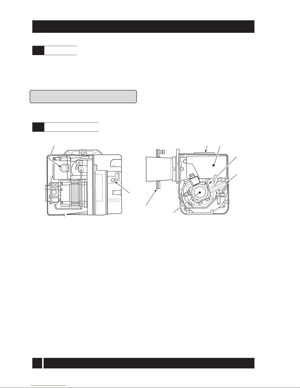
36
1 Pump
2 Control box
3 Reset
button with lock-out lamp
4 Flange with gasket (do not remove
from boiler)
6 - BOILER INSTALLATION
Please ensure that the OFTEC CD/10
installation completion report (provided
with the boiler) is completed in full.
Leave the top copy with the User. Retain
the carbon copy.
Ensure that the User Information pack (supplied
with the boiler) is handed over to the Householder.
Fig. 20 - Riello RDB burner components
5 Air damper adjustment scre
w
6 Air supply tube connection (balanced flue)
7 Pump pressure adjustment screw
8 Pressure gauge connection
7
8
1
23
5
4
6
iQE Horizon Internal Oil Boiler
6.12
Burner components
6.11
Completion
Page 38
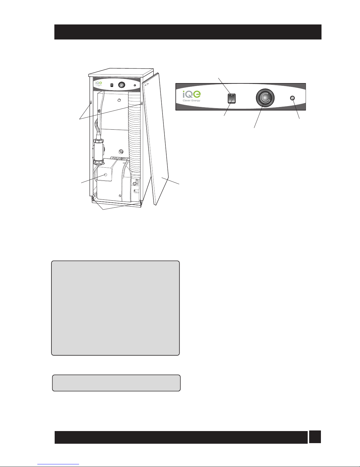
37
Refer to Fig. 21 for boiler controls
It is important that the following commissioning
procedure is carried out to ensure safe and
efficient operation of the boiler.
Note: Check that the baffles are in position and that
the cleaning cover is correctly fitted
and a good seal
made.
IMPORTANT:
Check that the turbulators are
in position and that
the ends are vertical (see Fig. 26).
Notes: 1. If the 15/26 model is down rated to 15 kW,
the burner air adjuster di
sc must also be
adjusted
to
setting B as
described
overleaf.
See Section 3.3.
2.
If the 15/26 model is down rated to 21 kW, the
burner head must also be changed to a T1
head. See Section 3.3.
1 Check that the water system has been vented (and
pressurised if sealed system) and there are no leaks.
Ensure the automatic air vent on the
condensing heat exchanger is open.
2 Check that all fuel line valves are open.
3 Remove the plastic burner cover if it was not
previously removed.
4 Connect a combined vent manifold and
pressure gauge to the pressure gauge connection
port on the oil pump. See
Fig. 7. Open the vent screw
on your vent manifold to vent the supply while the
pump is running.
5 Set the boiler On/Off switch to Off. Check that all
system controls are calling for heat and
turn the boiler thermostat to maximum.
Switch on the electricity supply.
6 Set the boiler On/Off switch to On. The burner fan
should start and the burner should light within
about 12 seconds. If the burner does not light
and the 'Lock-out' reset button lights, wait for
about 45 seconds then press the reset button
to restart the ignition process. This procedure
may have to be repeated several times during
first lighting.
7 With the burner alight, check the fuel pressure.
Refer to the Technical Information, Section
3.3. Adjust the pressure if necessary - see
Fig. 7. Note that the 'Mains On' neon lights
when the boiler is switched on, but does not
necessarily indicate the burner is firing.
8 Operate the boiler until it reaches normal operating
temperature. Check oil supply/return pipe for
leaks, rectifying where necessary.
7 - COMMISSIONING
Fig. 21
Boiler
thermostat
Overheat
thermostat
reset button
(under cover)
On/Off
switch
OVERHEAT
RESET
HEATING
TEMPERATURE
OVERHEAT
RESET
BOILER
OFF
ON
HEATING
TEMPERATURE
ON
BOILER
OFF
Lock-out
button
Front panel removed
(pull forward at top, then lift off)
Front panel
fixing clips
Front panel bottom locating tags
GRANT
Mains On
neon
iQE Horizon Internal Oil Boiler
Page 39
38
7 - COMMISSIONING
9 Check the operation of the boiler thermostat.
Ensure that by turning it anticlockwise it switches
the burner off.
10 With the burner alight, re-check the fuel pressure
and r
e-adjust if necessary. Turn the boiler off,
remove the pressure gauge and replace the plug
in the pump.
11 Having ensured that there are no oil leaks, replace the
burner cover. Ensure the flexible air tube is
con
nected to the burner (balanced flue models).
12 Relight the boiler and allow it to run for at least 20
minutes.
13 Check the smoke number, if satisfactory check
the CO2. Set the CO2 to the value given in
Section 3.3 for the boiler concerned.
Use the hexagonal key supplied to adjust the
burner air
damper (see Fig. 20) as required.
Turning the screw anti-clockwise closes the
damper and increases CO2 level, turning the
screw clockwise opens the damper and reduces
CO2 level.
Re-check the smoke number if the damper has
been moved. Under no circumstances must the
smoke number be above 1.
Note: It is important that the air damper
is correctly set.
14 Check the flue gas temperature.
15 Check that both the boiler overheat and boiler
conmtrol thermostat bulbs are correctly
located in their respective pockets. For
location of thermostat pockets, refer to Fig. 12.
Also check the condition of both thermostat
capillaries, i.e. that they are not damaged,
broken or kinked, and that they are not
trapped or crushed between any internal
boiler components.
16 Replace the case top.
17 When the boiler has been adjusted and is running
satisfactorily, balance the central heating
system by adjusting the radiator lock shield
valves. Start
with the radiator nearest the boiler
and adjust the valves to achieve the required
temperature drop across each radiator. If
thermostatic radiator valves have been
installed, check the system by-pass.
18 Switch off the boiler.
19 With the system hot, check again for leaks,
rectifying where necessary. Drain the system
while it is hot to complete the flushing process.
Refill and vent (and pressurise if a sealed
system) the system.
20 A suitable central heating system inhibitor
must be added to protect the system
against the effect of corrosion.
21 Replace the front panel - Locate the bottom of
the panel over the fixing tags then push it
towards the boiler to engage the fixing clips.
Note: After commissioning the boiler complete
the Commissioning Report on page 2 of these
instructions and the OFTEC CD/11 commissioning
report. Leave the top copy with the User and
retain the carbon copy.
If the boiler is to be left in service with the User,
set the system controls to the User's
requirements.
If the boiler is not to be handed over
immediately, close the boiler fuel supply valve
and switch off the electricity supply.
If there is any possibility of the boiler being left
during frost conditions, then the boiler and
system should be drained.
IMPORTANT NOTE:
T
o allow the boiler t
o be commissioned and serviced
correctly
a
combustion test point is provided on the
front cleaning door.
The CO2 and smoke test may all be carried out
using this test point. The test point is not suitable
for measuring boiler efficiency or conventional flue
draught.
When using the test point on the cleaning cover
note that the flue gas temperature reading will be
higher than that measured in the flue thus resulting
in an inaccurate efficiency reading. To obtain an
accurate flue gas temperature and efficiency, the
reading can only be measured outside through the
low level flue terminal. For high level and vertical
balanced flues the reading may be taken from the
flue kit test point provided . Refer to Section 3.3.
For Conventional flue draught measurement and
efficiency a test point is provided in the
conventional flue adaptor.
To adjust the 15/26 air adjuster disc
when downrating - See Fig. 22
1.
Ensure the boiler is isolated from the electrical supply.
2.
Disconnect the air supply tube.
3.
Remove the burner from the boiler.
4.
Undo the two screws and remove the air inlet
cover from the side of the burner.
5.
The secondary air shutter disc is factory set in
position ‘C’ – i.e. with the cut-out marked C
located against the die-cast boss on the fan
housing - suitable for outputs of 18.3 and 21
kW only. See Fig 22.
iQE Horizon Internal Oil Boiler
Page 40
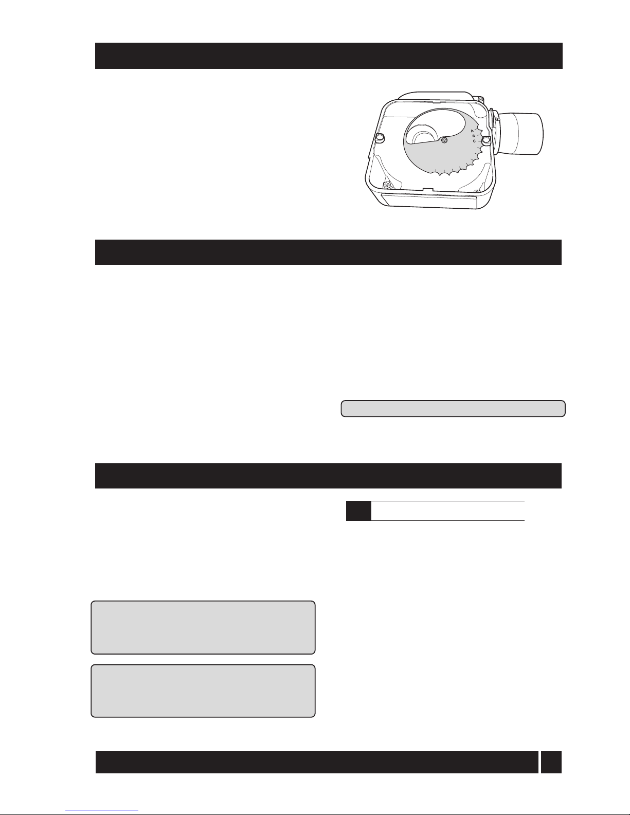
39
6. Remove the screw from the centre of the air
shutter disc, and re-position the disc such that
the cut-out ‘B’ (corresponding to 15 kW
output setting – See Section 3.3) is located
against the cast boss on the fan housing.
Replace the screw in the centre of the air
shutter disc and tighten.
7. Re-fit the air inlet cover to the side of the
burner and reassemble in reverse order.
7 - COMMISSIONING
D
E
F
G
H
L
M
I
Fig. 22 - 15/26 air adjuster disc
position 'C' 8 - INFORMATION FOR THE USER
The User must be advised (and demonstrated if
necessary
) of the following important points:-
1 How to light and turn off the boiler and how to
operate the system controls.
2 The
precautions necessary to prevent
damage to the cen
tral heating system and to the
building, in the event of the boiler not being in
operation during frost conditions.
3 The importance of servicing the boiler to
ensure safe and efficient operation. This
should normally only be required once a year.
4 The type of fuel used.
5 That any servicing or replacement of parts must
only be carried out by a suitably qualified engineer.
6 Ensure that the boiler controls and room
thermostat (if fitted) are set to the User's
requirements.
7 If the boiler is used on a sealed heating system, tell
the user the system pressure and show
them the position of the safety valve
discharge pipe.
8 Show the User how to reset the overheat thermostat
and how to
restart the boiler if it goes to 'Lock-out'.
Leave this Instruction manual with the User.
To ensure efficient operation of the boiler it is
recommended that it is
checked and serviced as
necessary at regular intervals. The frequency of
servicing will depend upon the particular
installation conditions and usage, but in general
once per year should be adequate.
Servici
ng and replacement of parts must only
be carried out by a suitably qualified engineer.
Important: Details of every service should be
entered in the Service Log, in the Boiler
Handbook. This information may be required to
validate the iQE warranty.
IMPORTANT
Before starting any work on the boiler, or fuel
supply please read the health and safety
information given in Section 14 on page 47.
9 - BOILER SERVICING
1 Check the flue terminal and ensure it is not blocked
or damaged.
2 Run the boiler and check the operation of its controls.
3 Ensure that all water/fuel system connections and
fittings are sound. Remake any joints and
ch
eck the tightness of any fittings that may be
leaking.
If the boiler is used on a sealed central heating
system, check the system pressure, check the
operation of the pressure relief valve and
check the expansion vessel air charge. See
Section 6.6. Refill, vent and re-pressurise the
system as necessary. See Section 6.11
4 Check that any ventilation openings are adequate
and are clear. See Section 4.7.
5 Remove any sludge/water from
the fuel tank
by opening the sludge valve at the low
er end of
the tank.
iQE Horizon Internal Oil Boiler
9.1
Important notes prior to servicing
Page 41
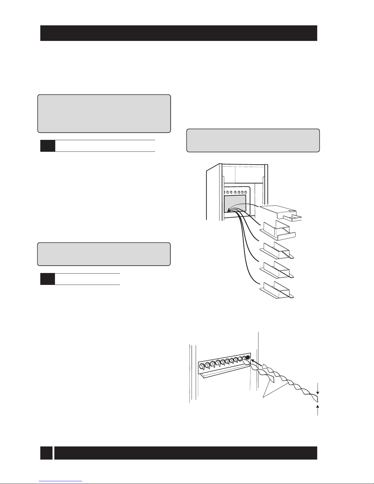
40
9 - BOILER SERVICING
6 With the fuel supply valve closed, clean/replace the
filter element and clean the filter bowl.
7 Flexible fuel supply hoses should be inspected annually
when the boiler is serviced and braided hoses
re
placed every year. If in doubt replace the hoses
Warning: Before servicing, set the boiler On/Off
switch to
Off, isolate the electricity supply and close
the fuel supply valve. Allow the boiler to cool. The
data label on the inside of the case side panel will
indicate the fuel used and the nozzle fitted.
1 Pull the front panel forward at the top to
disengage the fixing clips then lift it up and off
the boiler.
2 If a sealed system kit is fitted, carefully lift up and
remove the expansion vessel from the front of
the boil
er. Place the vessel on the floor taking
care not to strain the flexible pipe.
3 Disconnect the flexible air tube from the burner.
4 Remove the burner fixing nut (top of mounting
flange) and withdraw the burner. If required,
d
isconnect the flexible oil hose(s), use a
suitable container to prevent any oil spillage.
Note: If two flexible hoses are connected to the
burner,
identify (mark if necessary) which is the
inlet and return if they are to be disconnected.
1 Remove the nuts and washers securing the front
cleaning door and withdraw the door. Take
care - it is heavy.
2 Remove the baffles as shown in Fig. 23.
3 Remove all deposits from the baffle plates and all
the bo
iler internal surfaces using a stiff brush and
scraper if necessary.
4 Check the condition of the flue, clean as necessary.
5 Check the condition of the front cleaning door seal,
replace if necessary.
6 Replace the baffles, ensuring they are correctly
fitted. See Fig. 23.
7 Pull out the spiral turbulators from the heat
exchan
ger tubes. See Fig. 24.
Clean the turbulators using a stiff brush
Test the heat exchanger condensate drain by
pouring water into one of the lower tubes and
observe whether the water discharges from the
22 mm condensate outlet. Replace the
turbulators.
Fig. 23 - Baffles
8 Replace the front cleaning door, ensuring the seal
i
s in good condi
tion and secure it in position with
th
e nuts and washers previously removed.
Tighten to form a seal.
9 Remove the condensate trap and check that it is not
b
loc
ked and is operating correctly, i.e. the float is
f
ree to move. Clean the trap and float as required.
10 Check that the boiler condensate outlet is
unobstructed. Clean if necessary.
IMPORTANT: The condensate trap and
condensate outlet must be checked on every
service and cleaned as necessary.
2
1
3
4
5
Turbulators
IMPORTANT:
The ends of the
turbulators
must be vertical
Position in vertical plane
Fig. 24 - Turbulators
iQE Horizon Internal Oil Boiler
9.2
Dismantling prior to servicing
9.3
Cleaning the boiler
Page 42
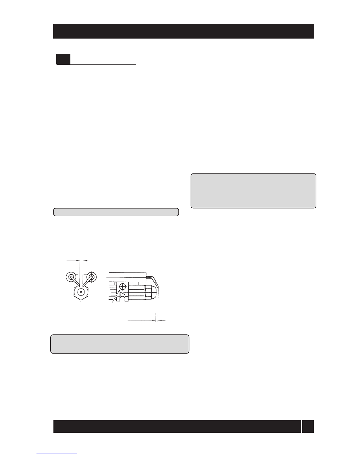
41
9 - BOILER SERVICING
4 ± 0.3 mm
3 to 3.5 mm
Clamp screw
Fig. 25
IMPORTANT: The electrode settings given
above MUST be observed.
See Section 13.1
1 Combustion head - Loosen the two screws
se
cur
i
ng the combustion head and withdraw
the head. Clean and refit the combustion head.
2 Inspect the ignition electrodes - Remove the
combustion head. Loosen the electrode clamp
screw and
withdraw the electrode assembly.
Wipe clean and check for any cracks in the
ceramic insulation. Replace if necessary.
Check the electrode settings
Electrode tips approximately 4 mm apart and
3 to 3.5
mm in front of the nozzle, see Fig 25.
3 Nozzle - The nozzle should be replaced on an
annual service - Check that the nozzle size and
type are correct, refer to table in Section 3.3
and boiler data label.
With the combustion head removed, loosen
the electrode assembly clamp screw and
slide the electrodes away from the nozzle.
Do NOT attempt to clean the nozzle.
Remove the nozzle using a good fitting
spanner (16 mm). The use of an ill-fitting
spanner will damage the nozzle and could
lead to an incorrect flame pattern. Always
check the electrode settings after replacing
the nozzle, see Fig. 25.
All models
1 Photocell - The photocell is a push-fit in the burner
body. Carefully pull out the photocell to clean.
2 Burner fan - With the air intake grille or spigot
removed, remove the screws securing the fan
housing cover (R/H side of burner) and
remove the cover. Inspect the fan and housing
and clean as necessary. Replace the cover.
3 Pump filter - With the burner cover removed,
remove the four screws securing the pump
end cover. Remove the filter and wash in
kerosene. Replace the filter and end cover,
ensure the 'O' ring is in position.
Re-assemble in reverse order.
To ensure safe and efficient operation of the
boiler it is important that re-commissioning is
carried out, especially combustion checks (CO
2
level, flue gas temperature and smoke number)
after the boiler has been serviced.
Refer to the Commissioning instructions
starting on page 37.
iQE Horizon Internal Oil Boiler
9.4
Cleaning the burner
Page 43
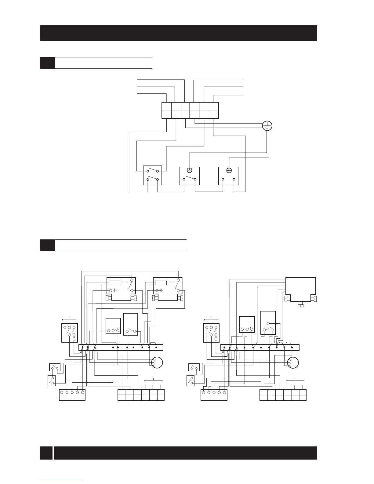
42
Fig. 26
10 - WIRING DIAGRAM
Fig. 27
Limit
Thermostat
Control
Thermostat
2
C
1
C
1A 2A
E
N
L
E
N
L
1
2
3
4
5
6
E
N
L
E
N
L
Supply to
Burner
Mains Supply: Use 2
pole isolator with
power "ON" indicator
G/Y
G/Y
G/Y
R
Bl
Bl
Br
Br
Br
Colour code: Br - Brown, Bl - Blue, R - Red, G/Y - Green/Yellow
Boiler
On/Off
G/Y
4B
5B
G/Y
Bl
Br
G/Y
Bl
Br
Boiler Terminal Block
E N L
240 V
50 HZ
LNE
Supply to
Burner
Frost
Stat
Pipe Stat
(if fitted)
1 34NL
Pump
E
N
L
Wiring
Centre
1
2
3
45678910
Boiler Terminal Block
1 23456
LNE
ENL
CH and HW controlled by 3-port mid position valve
Cylinder
Stat
1
C2
Room
Stat
213
3-Port
Mid Position
Zone Valve
Blue
Green/Yellow
White
Grey
Orange
CH & HW controlled by two 2-port zone valves
Cylinder
Stat
1
C
Room Stat
21
3
2-port
Zone Valve
Motor
HTG
2-port
Zone Valve
Motor
DHW
Grey
Blue
Blue
Brown
Brown
Orange
Green/Yellow
Green/Yellow
Orange
Grey
Frost
Stat
Pipe Stat
(if fitted)
1 34NL
E N L
240 V
50 HZ
Pump
E
N
L
Wiring
Centre
1
2
3
45 6 7 8 9 10
Boiler Terminal Block
1 23456
LNE
ENL
LNE
Supply to
Burner
iQE Horizon Internal Oil Boiler
10.1
Control panel wiring diagram
10.2
Typical control system wiring diagrams
2 channel
Programmer
2 channel
Programmer
Page 44
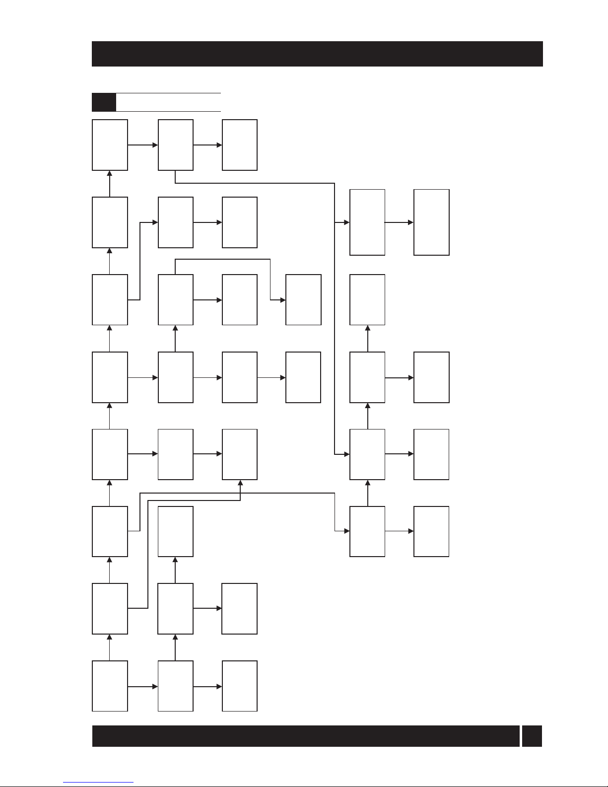
43
11 - FAULT FINDING
Motor/pump
seized
ortight
Replace
motor
capacitor
Burner
motor runs
Check L&N
tocontrol
box
Check
boiler
controls
Motorgives
50Volts
to white wire
*
Replace
burner
motor
Repair
orreplace
motor/pump
Lockout
after 12sec
purge
Lockout
within
1second
Replace
solenoid
coil
Coilof
solenoid
sound**
Repairor
replace
oilpump
Washing
pressure
1to2bar
Photocell
sound***
If balanced flue,
remove air tube
and retest
Reseal
balanced flue
or reposition flue
Replace
photocell
Drive
coupling
broken
Pump
produces
pressure
Replace
nozzle
Contaminated
fuelor
filter
Combustion
airset
Flameoff
and
relights
Boileror
flue
blocked
Combustion
headset
YES
NO
YES
YES
YES
YES
YES
YES
YES
YES
YES
YES
YES
YES
YES
NO
YES
NO
NO
NO
Checkand
set the
electrodes
Replace
the
control box
Ignition
spark
proved
NO
NO
NO
NO
NO
OK
NO
NO
NO
NO
Solenoid
valve
operating
Replace
control
box
Checkoil
pressure
regulator
Replacecoil
and/or
stemvalve
Nozzle
atomising
fuel
NO
YES
NO
NO
Notes
*
**
***
Motorwhitewirereturns50-53VAC tocontrol box.
Test solenoid coil for continuity or 100 ohms.
Test photocell by disconnecting it in
control box. If burner fires and then goes
to lockout, photocell should be replaced . It
is best to replace the photocell if it is
suspect.
Burners on balanced flue systems can
recirculate flue product scausing burner
recycling. If this happens, check flue
position and sealing.
iQE Horizon Internal Oil Boiler
11.1
Burner fault finding
Page 45

44
11 - FAULT FINDING
Warning: Always isolate the electricity supply to the boiler before working on the boiler.
Ensure that an adequate supply of fuel is available and that the
fuel supply valve is open.
Check the condition of the fuel filter, clean if necessary.
Ensure fuel supply is reaching burner and vent pump.
Ensure electricity supply to the boiler is switched on and that all
controls are
calling for heat. Ensure that the overheat thermostat has
not tripped, reset if necessary. Check that a mains supply is present at
the burner terminal block. If not, check the boiler and overheat
thermostat.
Press the reset button on the burner control box if it
i
s lit. Refer to burner fault finding flow diagram.
If the flame is unstable, check the combustion settings. Refer
to burner
fault finding flow diagram.
Insufficient air supply - check the air damper setting and the
condition of the fan. Check room ventilation is adequate, see
Section 4.6. Check the nozzle size and type.
Fuel pressure may be too high - check and adjust.
Insufficient air supply - check the air damper setting and the
condition of the fan. Check room ventilation is adequate, see
Section 4.6. Check the nozzle size and type.
Insufficient air supply - check the air damper setting and the
condition of the fan. Check room ventilation is adequate, see
Section 4.6. Check the nozzle size and type.
Fuel pressure may be too low - check and adjust.
Insufficient draught - clean boiler heat exchanger and check
condition of flue.
Undersize nozzle and/or low fuel pressure.
Check condition of boiler heat exchanger and clean if
necessary. Check the boiler thermostat.
Check the combustion settings.
Check the condition of the fuel filter.
Faulty boiler thermostat.
Check the condition of the chimney, ensure it is not blocked and
is high enough to produce the required draught.
Check that there is an adequate air supply near the burner and
that a kitchen fan is not drawing products out of the burner.
Check all fuel line connections, remake as necessary.
Check boiler cleaning cover and seal are
correctly fitted. Check burner is correctly fitted
onto flange.
Check flue is correctly sealed into flue outlet of
boiler. Check the condensate pipe and trap are
operating correctly.
RemediesFaults
Boiler will not start
1 No fuel supply.
2 No electricity supply.
3 Burner not starting - fuel and
electricity supplies present.
4 Burner lights but goes to 'lock-out'.
Boiler works but:-
5 Visible smoke from flu
e or high
smoke number.
6 Burner pulsates.
7 Flame slow to stabilise during start up.
8 Water temperature low.
9 Boiler operating on overheat
thermostat.
10 Fumes and puffing during starting
(conventional flue).
11 Oil odours.
12 Combustion fumes smell.
iQE Horizon Internal Oil Boiler
11.2
Boiler fault finding
Page 46
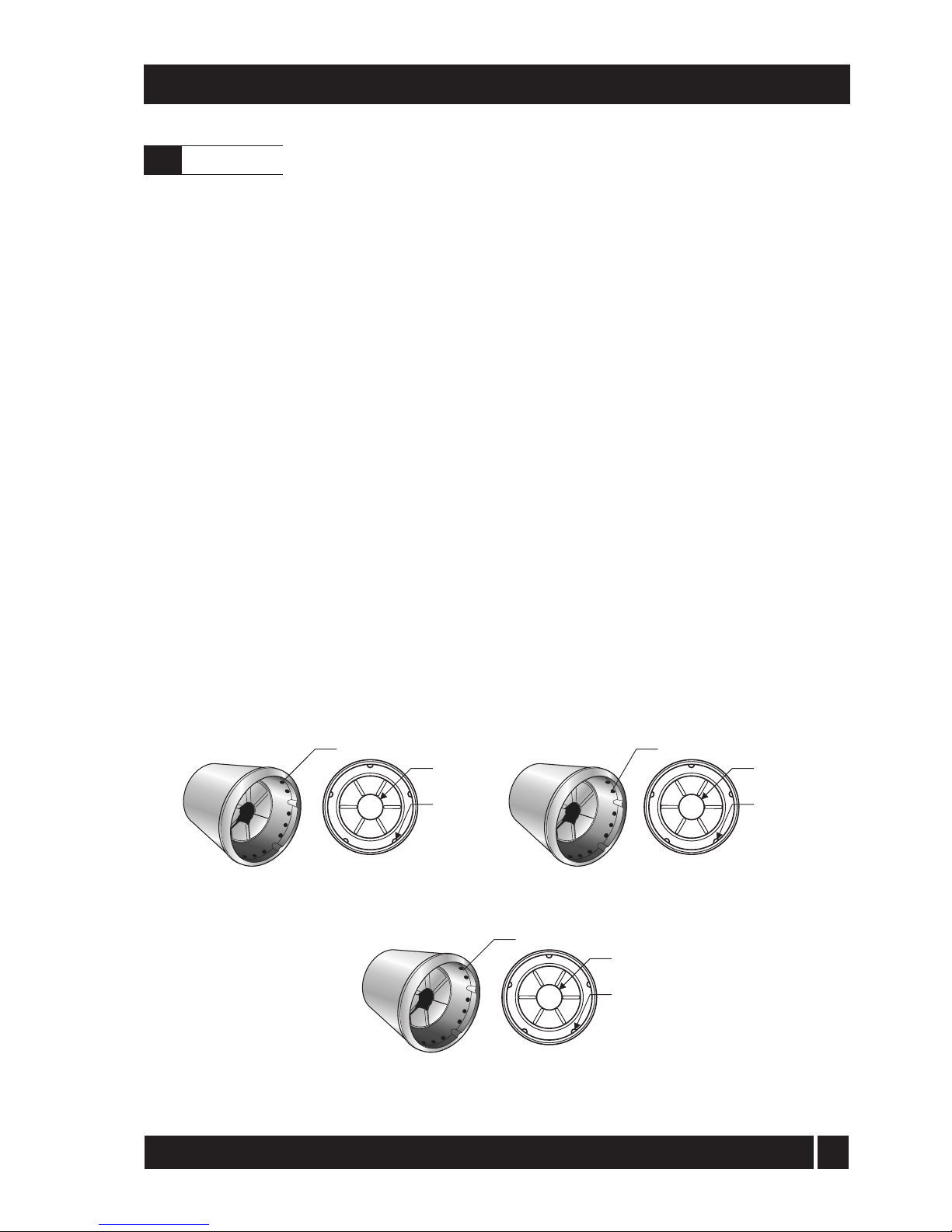
45
Description
Part No.
Double pole On/Off switch (with neon) ............................................ iQE01
Return connection assembly (22 mm) with auto air vent.......... iQE02
High limit thermostat ...................................................................................iQE04
Control thermostat .......................................................................................iQE05
Snorkel tube ....................................................................................................iQE22
Baffle set (complete) - 15/21 and 21/26 .............................................. iQE07
Baffle set (complete) - 26/35 ..................................................................iQE08
Turbulator (single) - 15/21 and 21/26 ................................................... iQE09
Turbulator (single) - 26/35 ...................................................................... iQE09
Combustion door - 15/21 and 21/26 ..................................................... iQE10
Combustion door - 26/35 ......................................................................... iQE11
Combustion door seal - 15/21 and 21/26 ............................................ iQE12
Combustion door seal - 26/35 ................................................................ iQE13
Expansion vessel - 12 litre .......................................................................... iQE14
Pressure relief valve...................................................................................... iQE15
Circulating pump - 6 m head .................................................................. iQE16
Pump valves (set of 2) - 22 mm ............................................................. iQE17
Condensate trap ............................................................................................ iQE20
Condensate flexible hose ........................................................................... iQE21
Burner Heads
12 - BOILER SPARE PARTS
20 dia.
15 x 4.5dia.
5 x R5
T2 - 15/26 and 26/35
20dia.
15 x 5.5dia.
5 x R5
T3 - 26/35
18dia.
15 x 4dia.
5 x R3
T1 - 15/26
12.1
Spare Parts
iQE Horizon Internal Oil Boiler
Page 47
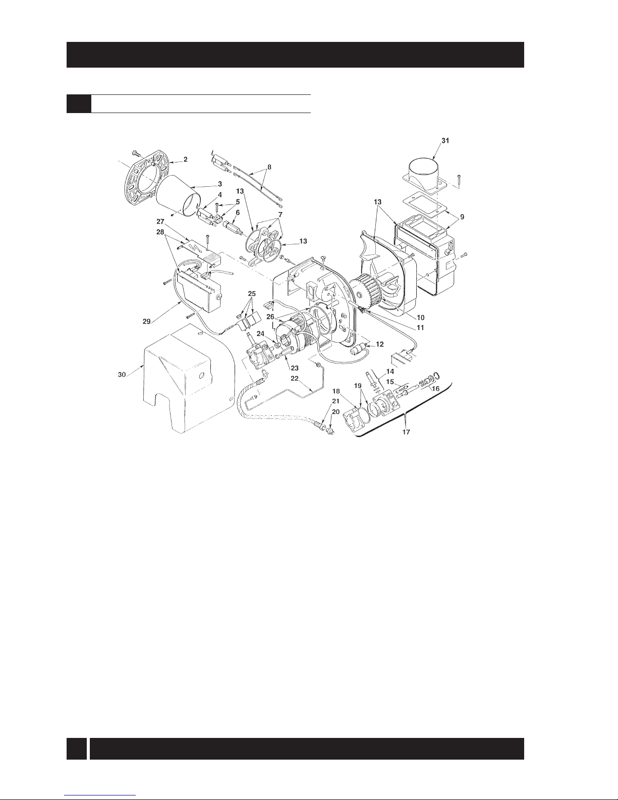
46
13 - BURNER SPARE PARTS
1 Not applicable 2 Flange
3005786
3 Combustion head T1 - 15/26 3002507
3 Combustion head T2 - 21/26,26/35 3002423
3002447
3 Combustion head T3 - 26/35
4 Electrode assembly
5
Electrode bracket
6 Nozzle holder
7 Collar
8 High voltage lead
9 Air damper assembly
10 Fan
11 Photocell
12 Capacitor 4.5 µF
13 Seal kit
14 Needle valve
15 Regulator
3007513 RBS108
3006
552 RBS29
3008642 RBS111
3008643 RBS112
3008794 RBS129
3008647 RBS116
3005788 RBS151
3008646 RBS115
3002837 RBS149
3008878 RBS140
3007582 RBS109
3008651 RBS120
Key Description
Riello
Part No.
Key Description
Riello
Part No.
3000439 RBS14
3008654 RBS101
3007162 RBS08
3008653 RBS122
3003602 RBS35
3007672 RBS36
16 Pump seal
17 Pump
1
8 'O' ring
19 Filter - 'O' ring
20 Connector
2 1 Flexible pipe
22 Tube
23 Pressure gauge connector
24 Drive coupling
25 Solenoid
26 Motor RBS102
27 Cover
28 Control box assembly
29 Solenoid lead
30 Cover
3 1 Air tube spigot
3008644 RBS113
30
08876 RBS138
3000443 RBS16
3008648 RBS117
3002836 RBS102
3008649 RBS118
3008652 RBS103
3008851 RBS139
3008879 RBS141
3062774 RBS143
iQE Horizon Internal Oil Boiler
13.1
Riello RDB1, 2, 2.2 burner - exploded view
Page 48

47
14 - HEALTH AND SAFETY INFORMATION
Under the Consumer Protection Act 1987 and Section 6 of the Health & Safety at Work Act
1974, we are required to provide information on substances hazardous to health (COSHH
Regulations 1988).
Adhesives, sealants and paints used in the manufacture of the product are cured and present
no known hazards when used in the manner for which they are intended.
The following other materials are present in the product:
Insulation materials
Material Types: Ceramic fibre board, mineral wool.
Description: Rigid board, slabs, sleeves, gaskets, ropes.
Known Hazards: May cause temporary irritation or rash to skin. High dust levels may irritate eyes
and upper respiratory system.
Precautions: Avoid unnecessary or rough handling, or harsh abrasion of boards. Normal
handling and use of material should not produce high dust levels.
Avoid inhalation, and contact with skin and eyes.
After handling always follow normal good hygiene practices.
Protection: Use disposable gloves, face mask and eye protection.
First Aid: Eyes - If irritation occurs, wash eyes with copious amounts of water. If
symptoms persist, seek immediate medical advice.
Skin - If irritation occurs, wash under running water before washing with soap
and water. Inhalation - Remove to fresh air, drink water to clear throat and
blow nose to remove dust/fibres. Ingestion - Drink plenty of water.
Sealants
Material Types: Silicone elastomer.
Description: Sealant and adhesive.
Known Hazards: Irritation to eyes.
Precautions: Avoid inhalation of vapour, contact with eyes and prolonged or repeated contact with
skin. After handling always follow normal good hygiene practices.
Protection: Use eye protection. Rubber or plastic gloves should be worn where repeated
contact occurs and a face mask worn when working in confined spaces.
First Aid: Eyes - Flush eyes with water for 15 minutes. Seek immediate
medical attention. Skin - Wipe off and wash with soap and water.
Inhalation - Remove to fresh air.
Kerosene and Gas oil fuels (Mineral oils)
Known Hazards: The effect of mineral oils on the skin vary according to the duration of exposure
and the type of oil. The lighter fractions remove the protective grease naturally
present on the skin, leaving it dry, liable to crack and more prone to damage by
cuts, abrasions and irritant chemicals. Skin rashes (Oil acne) most often on arms,
but also on any part of the body in contact with oil or oily clothing.
Contact with fuel oils can cause dermatitis.
Precautions:
Avoid as far as possible any skin contact with mineral oil or with clothing
contaminated with mineral oil. The
use of a lanolin-based barrier cream is
recommended, in conjunction with regular washing with soap and rinsing with water
to ensure all oil is removed from the skin. Take care to prevent clothing, especially
underwear, from becoming contaminated with oil. Do not put oily rags or tools in
pockets, especially trouser pockets. Have first-aid treatment at once for an injury,
however slight. Do not inhale any vapours from mineral oils.
iQE Horizon Internal Oil Boiler
Page 49
W
e d
eclare that the iQE Horizon
range of Oil Boilers equipped with
Riello RDB burners approved to
EN 267: 1991 satisfy
the
requirements of the following
European Directives:-
89/336/EEC Electromagnetic
Compatibility Directive
Referred to the generic
standards EN 55014: 1993, EN
50082: 1: 1992
73/23
/EEC - Electrical Equipment
Safety Regulations Directive
Referred to the generic standard
NO: 3260: The Electrical Equipment
(Safety) Regulations: 1994
In non-EU countries, dispose of
electrical and electronic equipment
and all surplus packaging in
accordance with national and
regional regulations.
Disposal of Surplus Packaging
European Parliament and
Council Directive 94/62/EC
Packaging and Packaging
Waste.
Do not dispose of surplus
packaging in landfill sites. In the
EU, it is the individual recipient’s
r
esponsibility to ensure that
packaging materials are collected
and recycled according to the
requirements of EU environmental
law.
In EU Countries
The following information is
provided to enable regulatory
compliance with the European
Union (EU) directive
s identified
and any amendments made to
these directives when using
electrical or electronic equipment
in EU countries.
Disposal of Electrical and
Electronic Equipment
E
uropean Union (EU) Directive
200
2/96/EC Waste Electrical and
Electronic Equipment (WEEE).
Do not dispose of electrical or
electronic equipment in landfill sites.
In the EU, it is the individual
recipient’s responsibility to ensure
that discarded ele
ctrical or electronic
materials are collected and recycled
according to the requirements of EU
environmental law.
92/42/EEC - Hot Water Boiler
Efficiency Directive
Referred to the generic standard
The Boiler (Efficiency)
(Amendment) Regulations 1994
(S
I 1994/3083).
In non-EU Countries
Complies with EC Low voltage
Electromagnetic compatibility
and Boiler efficiency Directives.
89/336/EEC
73/23/EEC
92/42/EEC
iQE Horizon Internal Oil Boiler
48
15 - EC Declaration of Conformity
Page 50

Terms and conditions
of the iQE Warranty
All iQE boilers are manufactured and
supplied with a Standard 5 year Warranty.
This standard offer includes parts
and labour within the appliance. Flue
systems and external iQE accessories such
as Time Programmers are not covered
under the boiler warranty.
During the period of the warranty we will, at
our discretion, repair or replace a boiler free
of charge where it suffers a mechanical or
an electrical breakdown as a result of
defective workmanship or materials, subject
to the following conditions and exclusions:
1.
The boiler must have been installed
by a registered OFTEC installer and
commissioned in accordance with
the guidelines in the installation and
servicing booklet provided with the
boiler. The validity of the installer’s
OFTEC registration number will be
checked in all cases, where
appropriatte.
2.
The boiler must be registered
with iQE within 30 days of
installation.
3.
The CD10 installation form sheet
within the Installation and Servicing
manual must be completed by the
installer and left with the boiler for
reference purpose. A CD11 must be
completed by the Commissioning
Engineer.
4.
The warranty will commence from the
date of installation. Without proof of
purchase i.e.an invoice the warranty will
commence from the date of manufacture
as detailed on the appliance data plate.
5.
To qualify for the warranty the boiler
must also be serviced annually by
a qualified engineer and the work
documented in the Installation Guide.
6.
I f the boiler suffers a mechanical or an
electrical breakdown we should be
contacted on the following number: UK:
0800 0152252. Our normal working
times, excluding Bank holidays are:
8.30am - 5.00pm Monday to Friday. We
will arrange for an engineer or appointed
contractor, to inspect and repair, or
where in our opinion repair is not
economic, arrange to replace the boiler.
Please note:
Engineers will only attend to boiler products
where it is considered by the engineer that
the installation does not pose a risk to health
and safety. A permanently fixed access ladder
must service installations in lofts or attics and
adequate lighting and permanently fixed
flooring must be available. Cupboard
installations must provide minimum working
clearances as detailed in the installation
instructions. iQE will not accept responsibility
for the removal of cupboards, kitchen units or
trims in order to gain access for repairs.
16 -
Warranty
iQE Horizon Internal Oil Boiler
49
Page 51

7.
The warranty does not apply:
• I f the boiler is removed from its place of
installation without our prior consent.
• To any defect, damage or breakdown
caused by inadequate servicing of the
boiler or by deliberate action,
accident, misuse or third party
interference including modification or
an attempted repair which does not
fully comply with industry standards.
• To any defect, damage or
breakdown caused by the design,
installation and maintenance of
the central heating system.
• To de-scaling or other work required
as a result of hard water scale
deposits or from damage caused by
aggressive water or sludge resulting
from corrosion. Indications that such
work may be required include a noisy
boiler, cold spots on radiators, sludge
in pipes and poor circulation of the
central heating system.
• I f the claim/contact procedure set
out in section 6, is not adhered to.
• To any other costs or expenses
caused by or arising as a result of
the breakdown of an iQE boiler.
• To any defect resulting from the
incorrect installation of the boiler,
the flue system or the facility
for condensate disposal.
• To any costs incurred during
delays in fixing reported faults.
8.
We reserve the right to a charge a
callout fee of £85 plus vat where:
•
There is no completed CD10
Installation and CD11 commissioning
sheet or equivalent control document
present.
A fault cannot be found.
• The breakdown or fault has been
caused by an event, which is excluded
from the warranty - refer to section 7.
• Failure to cancel an agreed appointment
prior to our engineer’s visit.
• The boiler is outside the period
of warranty or the conditions of
the warranty have not been met
– refer to sections 2, 3 & 4.
9.
If we fit replacement parts or replace a
boiler it will not extend the period of the
warranty. All replaced parts or boilers
will become the property of iQE.
10.
The warranty applies only where an
iQE boiler has been installed in a
domestic dwelling in mainland United
Kingdom, Northern Ireland and I.O.W.
to provide heat and/or hot water
to the central heating system.
Guarantor – iQE, Trade House, BA22 8RT
16 - Warranty
iQE Horizon Internal Oil Boiler
50
Page 52

5YEAR
W
A
R
R
A
N
T
Y
W
A
R
R
A
N
T
Y
0800 0152 252
www.iqe.co.uk
Five year limited
warranty
Customer Name .........................................................................................................................................
Address line 1 ...............................................................................................................................................
Address line 2 ..............................................................................................................................................
Post code etc ...............................................................................................................................................
Appliance details .......................................................................................................................................
Boiler Model ................................................................................................................................................
Serial Number ............................................................................................................................................
Flue Type .(circle)..............Low-level.......High Level.......Vertical.........Conventional..............
Installation Date .........................................................................................................................................
Installation Company OFTEC Registration Number ....................................................................
Installers Name............................................................................................................................................
Installers Telephone Number.................................................................................................................
Page 53

iQE is a new brand of highly advanced energy efficient
products designed to make domestic energy saving
simple. A consortium of leading manufacturers and
specialist installation contractors have come together
to create this unique product range. The range has
been cleverly developed to address all areas of
domestic energy saving needs in one holistic
approach, including insulating the building fabric;
providing heating and hot water; advanced control
and analysis of the home’s energy use and even
generating power for electricity, heating and hot
water from the earth’s elements with new
Microgeneration technology.
For more information on our range of energy efficient
products go to www.iqe.co.uk
Trade House,
Mead Avenue,
Houndstone Business Park,
Yeovil, Somerset BA22 8RT
Tel: 0800 015 2252
 Loading...