

iQe CP027 Installation Instructions Manual

CP027
INSTALLATION INSTRUCTIONS
The CP027 two channel programmer offers up to three on/off
periods a day for hot water and heating with a hot water boost and
heating advance facility.
Installation and connection should only be carried out by a
suitable qualified person and in accordance with the edition of the
IEE wiring regulation.
Warning : Isolate mains supply before commencing installation.
1
Two Channel 7 Day Time Control
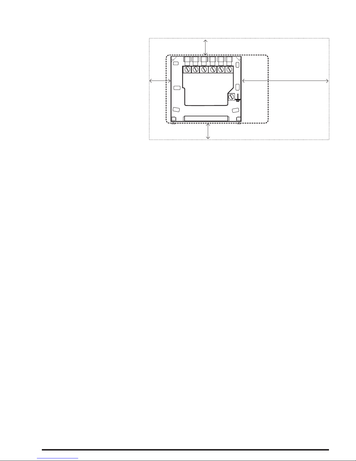
Fitting the backplate
Once the backplate has
been removed from the
p a c k a g i n g p l e a s e
ensure the programmer
is resealed to prevent
damage from dust and
debris.
The backplate should
be fitted with the wiring
terminals located at the top and In a position that allows a total
clearance at last 50mm around the unit.
Direct Wall mounting
Offer the backplate to the wall in the position where the
programmer is to be mounted, remembering that the backplate
fits to the left hand end of the control. Mark the fixing positions
through the slots on the backplate (fixing centres of 60.3mm), drill
and plug the wall, then secure the backplate position. The slots in
the backplate will compensate for any misalignments of the
fixing.
Wiring box mounting
The backplate may be fitted directly onto a single gang steel flush
wiring box complying with BS4662 using two M3.5 screws. The
CP027 is suitable for mounting on a flat surface only, they must
not be positioned on a surface mounted wall box or on unearthed
metal surfaces.
2
N L
1 2 3 4
100mm
50mm
50mm
50mm
Electrical Connections
All necessary electrical connections should now be made. Flush
wiring can enter from the rear through the aperture in the
backplate. Surface wiring can only enter from beneath the
programmer and must be securely clamped. The mains supply
terminals are intended to be connected to the supply by means of
fixed wiring. Recommended cable sizes are 1.00 to 1.5 mm2.
The CP027 is double insulated and do not require earth
connection but an earth connection is provided on the backplate
for terminating cable earth connectors. Earth continuity must be
maintained and all bare earth connectors must be sleeved.
Ensure no earth conductors are left protruding outside the central
space enclosed by the backplate.
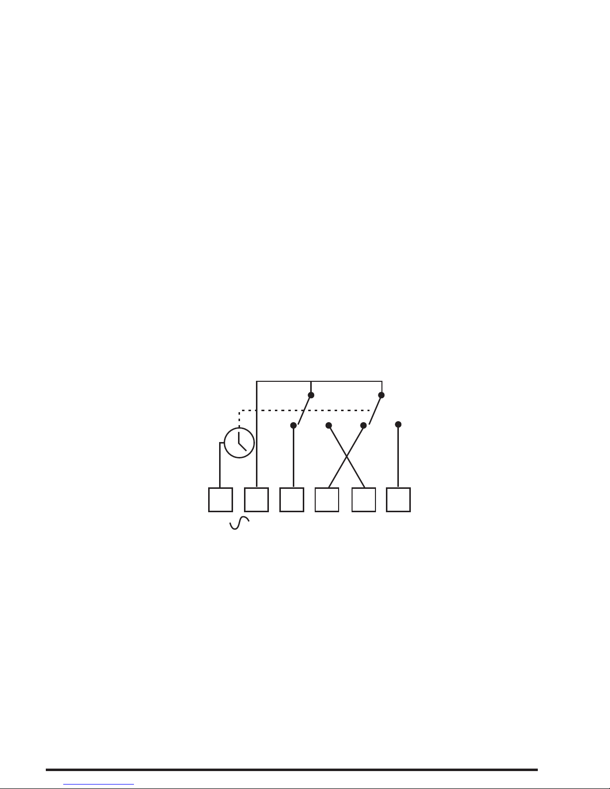
Internal wiring diagram - CP027
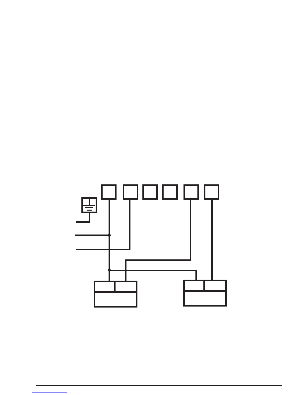
New Installations
Example circuit diagrams for some typical installations are
shown in the pages which follow. These diagrams are schematic
and should be used as a guide only.
Please ensure that all installations comply with current IEE
regulations.
N
L
1 2
3
4
OFF OFF ON ON
CHHW
HW
CH
230V 50Hz
3
For reasons of space and clarity not every system has been
included and the diagrams have been simplified – for example
some Earth connections have been omitted.
Other control components shown in the diagrams, i.e valves,
Room stats etc are general representations only. However the
wiring detail can be applied to the corresponding models of most
manufacturers.
Cylinder and Room Thermostat key;
C= Common; CALL = Call for heat or break on rise; SAT =
satisfied on rise; N = neutral.
4
N
L
1 2
3
4
PUMP
N
L
BOILER
N
L
MAINS
SUPPLY
E
N
L
1.Gravity Hot water with pumped heating
 Loading...