

iQe COMFORT 30 Installation And Servicing Instructions
INSTALLATION AND SERVICING INSTRUCTIONS
ENSURE THAT THESE
INSTRUCTIONS ARE LEFT
FOR THE USER AFTER
COMPLETION OF THE
BENCHMARK SECTION
PLEASE READ THE
IMPORTANT NOTICE
WITHIN THIS GUIDE
REGARDING YOUR
BOILER WARRANTY
UK
Cod. 6318139 - 10/2013

This boiler may require 2 or more operatives to move it into its installation site, remove it from its
packaging and during movement into its installation location. Manoeuvring the boiler may include
the use of a sack truck and involve lifting pushing and pulling.
Caution should be exercised during these operations.
Operatives should be knowledgeable in handling techniques when performing these tasks and the
following precautions should be considered:
– Grip the boiler at the base
– Be physically capable
– Use personal protective equipment as appropriate e.g. gloves, safety footwear.
During all manoeuvres and handling actions, every attempt should be made to ensure the following
unless unavoidable and/or the weight is light.
– Keep back straight
– Avoid twisting at the waist
– Always grip with the palm of the hand
– Keep load as close to the body as possible
– Always use assistance
WARNING
Caution should be exercised when performing any work on this appliance.
Protective gloves and safety glasses are recommended.
– Avoid direct contact with sharp edges.
– Avoid contact with any hot surfaces.
NOTICE
Please be aware that due to the wet testing of the appliance, there may some residual water in
the hydraulic circuit.
– Protect any surfaces, carpets or floorings.
– Use a suitable container to catch any water that escapes when removing the protective caps
from the connections.
SAFE HANDLING
IMPORTANT NOTICE
For the first year all of our appliances are protected by our manufacturer’s guarantee which
covers both parts and labour.
As you would expect from
, it is our aim to provide our valued customers with the best in
after sales and service.
To take advantage of any extended warranty offered, all you have to do is to adhere to these 3
simple conditions:
– The installation must be carried out to Manufacturers/Benchmark Standards by a Gas Safe
Registered Engineer, and recorded in the installation manual.
– The appliance must be registered with both
and Gas Safe within 30 days of installation.
– The appliance must be serviced annually, by or a Gas Safe registered engineer - ensuring that
the Benchmark service record in the installation manual is completed.
Failure to comply with the above will result in only the 12 month warranty being offered.
In the absence of any proof of purchase, the 12 month warranty period will commence from the
date of manufacture of the boiler as shown on the appliance data plate.
All descriptions and illustrations provided in this manual have been carefully prepared but we reserve the right to make changes and improvements in our
products that may affect the accuracy of the information contained in this manual.
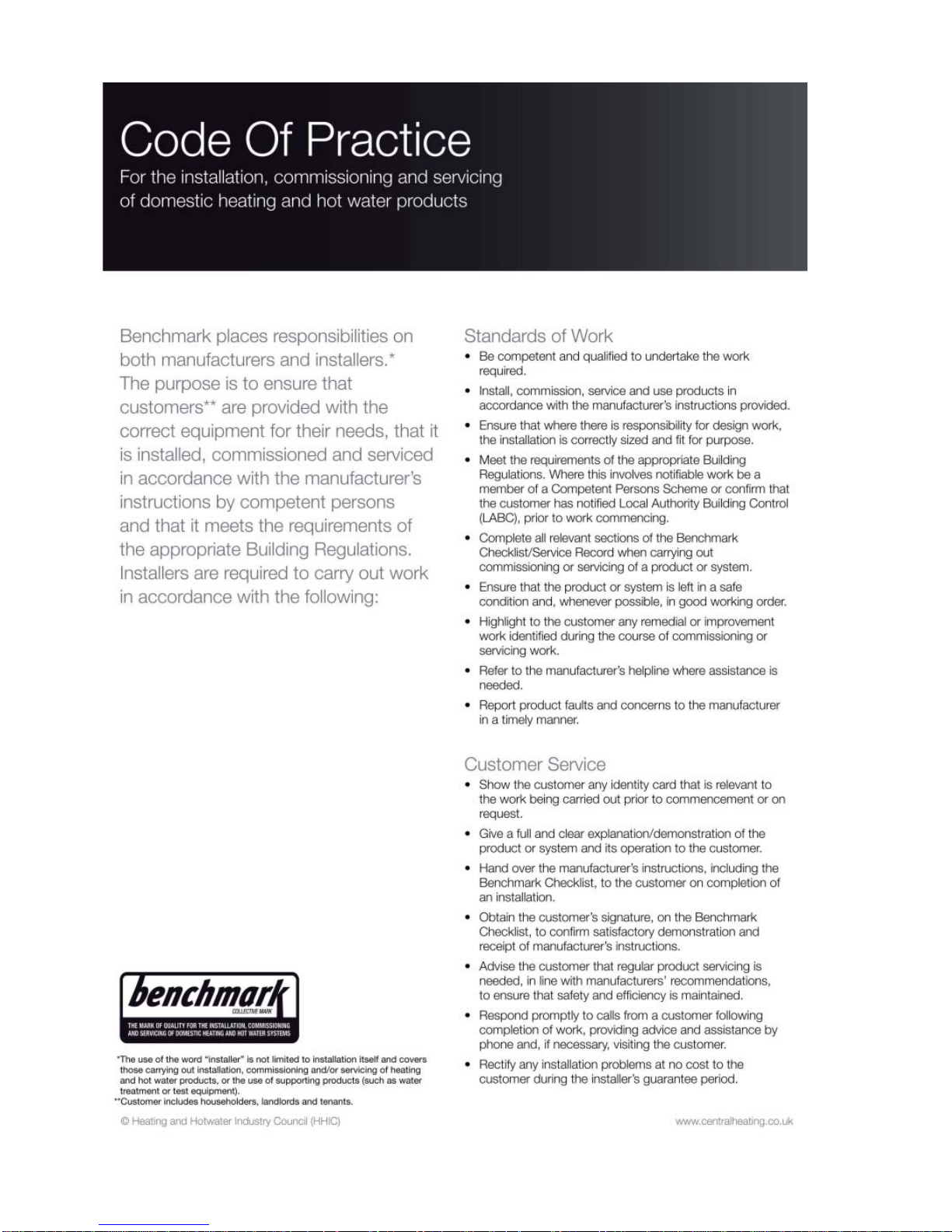

The Benchmark Scheme
The manufacturer is a licensed member of the Benchmark Scheme which aims to improve the standards
of installation and commissioning of domestic heating and hot water systems in the UK and to encourage
regular servicing to optimise safety, efficiency and performance.
Benchmark is managed and promoted by the Heating and Hotwater Industry Council.
For more information visit www.centralheating.co.uk
CONTENTS
1 DESCRIPTION OF THE BOILER ...................................................................................................... pag. 6
2 INSTALLATION ..................................................................................................................................... pag. 10
3 CHARACTERISTICS ............................................................................................................................. pag. 21
4 USE, MAINTENANCE (including BENCHMARK) AND COMMISSIONING ....................... pag. 23
5 FAULT FINDING .................................................................................................................................... pag. 27
6 REPLACEMENT OF PARTS .............................................................................................................. pag. 27
7 EXPLODED VIEWS .............................................................................................................................. pag. 30
8 APPENDIX 1 (GUIDANCE HHIC) ...................................................................................................... pag. 34
9 APPENDIX 2 ............................................................................................................................................ pag. 46
IPX4D
Please refer to commissioning instructions for filling in the checklist at the back of this
installation guide.
Note: All Gas Safe registered installers carry a ID Card.
You can check your installer is Gas Safe Registered by calling 0800 408 5577
COMBINATION BOILERS
Installer checklist
Please remember to carry out the following checks after installation. This will achieve complete
customer satisfaction, and avoid unnecessary service calls. A charge will be made for a service
visit where the fault is not due to a manufacturing defect.
– Has a correct by-pass been fitted and adjusted?
– Has the system and boiler been flushed?
– Is the system and boiler full of water, and the correct pressure showing on the pressure
gauge?
– Is the Auto Air Vent open?
– Has the pump been rotated manually?
– Is the gas supply working pressure correct?
– Is the boiler wired correctly? (See installation manual).
– Has the customer been fully advised on the correct use of the boiler, system and controls?
– Has the Benchmark Checklist in the use and maintenance section of this manual, been
completed ?
Important Information
IT IS A STATUTORY REQUIREMENT THAT ALL GAS APPLIANCES ARE INSTALLED BY COMPETENT
PERSONS, IN ACCORDANCE WITH THE GAS SAFETY (INSTALLATION AND USE) REGULATIONS
(CURRENT EDITION). The manufacturer’s instructions must not be taken as overriding any statutory
requirements, and failure to comply with these regulations may lead to prosecution.
No modifications to the appliance should be made unless they are fully approved by the manufacturer.
GAS LEAKS: DO NOT OPERATE ANY ELECTRICAL SWITCH, OR USE A NAKED FLAME. TURN OFF THE
GAS SUPPLY AND VENTILATE THE AREA BY OPENING DOORS AND WINDOWS CONTACT THE GAS
EMERGENCY SERVICE ON 0800111999.
COMFORT 30: Gas Council number 47-283-47
These appliances comply with the S.E.D.B.U.K. scheme, band “A”

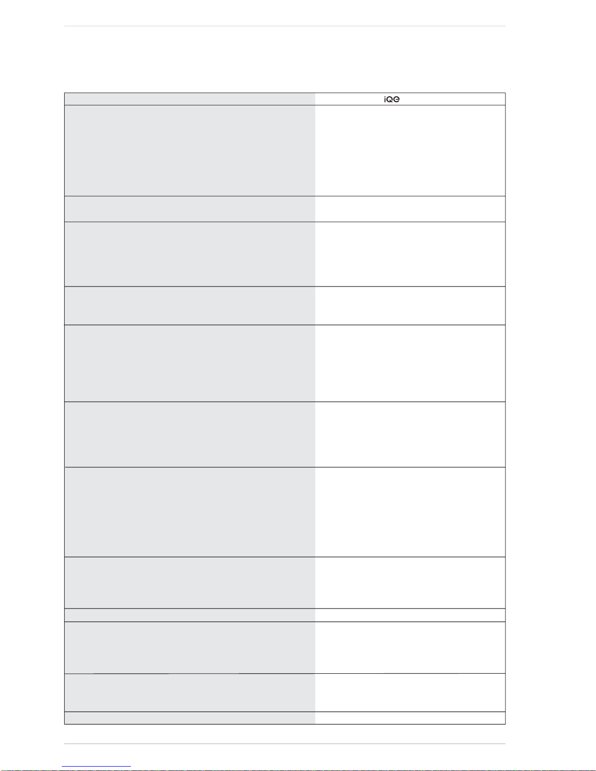
TABLE 2 - Minimum clearances
TABLE 1 - Connections
6
1.1 INTRODUCTION
COMFORT 30 are premixed gas
condensation thermal modules that
employ a microprocessor-based
technology to control and manage
all the functions.
All modules are compliant with
European Directives 2009/142/CE,
2004/108/CE, 2006/95/CE and
92/42/CE. For optimum installation
and operation, always follow
the instructions provided in this
manual.
The products manufactured and
sold by
do not contain any
banned materials or substances (ie
they comply with ISO9000:2000).
1 DESCRIPTION OF THE BOILER
65
6560
70
==
M
UGER
MUG E R
12 5
15
450
ø 60/100
13 9
18 3
50
39
30
10
63
S3
S
96
15
164
97
750
S3
290
Fig. 1
1.2 DIMENSIONS (fig. 1)
For servicing
ABOVE THE APPLIANCE CASING 200 mm
AT THE R.H.S. 15 mm
AT THE L.H.S. 15 mm
BELOW THE APPLIANCE CASING 200 mm
IN FRONT OF THE APPLIANCE 500 mm
R C.H. return 22 mm Compression
M C.H. flow 22 mm Compression
G Gas connection 15 mm Compression
E D.H.W. inlet 15 mm Compression
U D.H.W. outlet 15 mm Compression
S3 Condensation outlet ø 20
S Safety valve discharge
COMFORT 30
Heat output
Nominal (80-60°C) kW 28.9
Nominal (50-30°C) kW 31.6
Reduced G20 (80-60°C) kW 5.9
Reduced G20 (50-30°C) kW 6.6
Reduced G31 (80-60°C) kW 7.6
Reduced G31 (50-30°C) kW 8.5
Heat input nominal kW 29.5
Heat input reduced G20/G31 kW 6.2/8.0
Max/min useful yield (80-60°C) % 98.0/95.1
Max/min useful yield (50-30°C) % 107.1/106.4
Useful yield at 30% of the load (40-30°C) % 107.0
Termal efficiency (CEE 92/42 directive) ✰ ✰ ✰ ✰
Losses after shutdown to 50°C (EN 483) W 89
Supply voltage V-Hz 230-50
Adsorbed power consumption W 115
Electrical protection grade IP X4D
C.H. setting range °C 20/80
Water content boiler l 4.60
Maximum water head bar 3.0
Maximum temperature °C 85
Capacity of the heating expansion vessel l 8
Pressure of the heating expansion vessel bar 1.0
D.H.W. setting range °C 10/60
D.H.W. flow rate (EN 625) l/min 13.4
Continuous D.H.W. flow rate Δt 30°C l/min 14.4
Minimum D.H.W. flow rate l/min 2.2
D.H.W. pressure min/max bar 0.5/6.0
Exhaust fumes temper. at max flow rate (80-60°C) °C 79
Exhaust fumes temper. at min. flow rate (80-60°C) °C 67
Exhaust fumes temper. at max flow rate (50-30°C) °C 51
Exhaust fumes temper. at min. flow rate (50-30°C) °C 47
Smokes flow min/max kg/h 11/50
CO
2 at max/min flow rate G20 % 9.0/9.0
CO
2 at max/min flow rate G31 % 10.0/10.0
CE certification n° 1312CN5755
Category II2H3P
Type B23P-53P/C13-33-43-53-83
NOx emission class 5
Weight when empty kg 33.6
Main burner nozzle
Quantity nozzles n° 2
G20 nozzle diameter diversified ø 2.8/3.8
G31 nozzle diameter diversified ø 2.2/2.9
Consumption at maximum/minimum flow rate
G20 m
3
/h 3.12/0.66
G31 kg/h 2.29/0.62
Gas supply pressure G20/G31 mbar 20/37
7
1.3 TECHNICAL FEATURES

9
4
8
6
16
5
11
12
21
22
24
14
17
10
15
18
23
19
1
3
2
25
1.4 FUNCTIONAL DIAGRAM (fig. 2)
Fig. 2
8
KEY
1 Fan
2 Limit stat
3 Primary exchanger
4 C.H. sensor (SM)
5 Gas valve
6 D.H.W. exchanger
8 Diverter valve
9 Safety thermostat
10 Pump with air release vent
11 D.H.W. flow switch
12 Water inlet filter
14 Pressure relief valve
15 Water pressure switch
16 Automatic bypass
17 Drain vent
18 Expansion vessel
19 Condensate drain trap
21 D.H.W. isolation valve
22 Gas isolation valve
23 C.H. flow isolation valve
24 C.H. return isolation valve
25 D.H.W. sensor (SS)
CONNECTIONS
R C.H. return
M C.H. flow
G Gas connection
E D.H.W. inlet
U D.H.W. outlet
S3 Condensation outlet
S Safety valve discharge
9
04
13
2
bar
1
2
3
4
5
7
8
9
10
11
12
13
14
15
17
18
16
19
Fig. 3
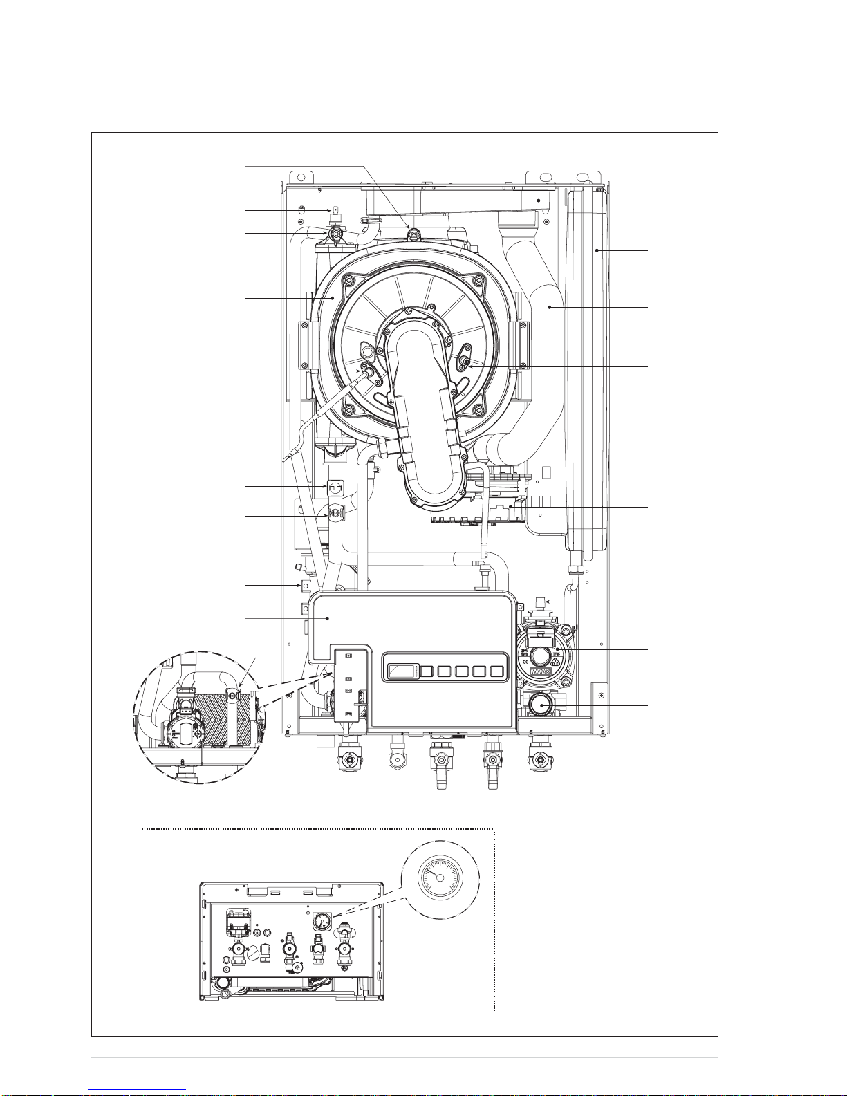
1.5 MAIN COMPONENTS (fig. 3)
KEY
1 Control panel
2 Condensate drain trap
3 C.H. sensor (SM)
4 Safety thermostat
5 Ignition electrode
7 Primary exchanger
8 Air release vent
9 Limit stat
10 Exhaust temperature sensor
11 Smoke chamber
12 Expansion vessel
13 Air inlet
14 Ionisation electrode
15 Fan
16 Pressure relief valve
17 Air release vent
18 Pump
19 D.H.W. sensor (SS)
NOTE: Analogue pressure gauge
It is important that the boiler is initially
filled and started for the first time using
the method shown in 2.3.3 section e).
This procedure should also be used
when refilling after draining a boiler.
The boiler must be installed in a fixed
location and only by specialized and
qualified person in compliance with all
instructions contained in this manual.
The installation of this boiler must
be in accordance with the relevant
requirements of the current Gas Safety
(installation and use), the local building
regulations, and and I.E.E. wiring
regulations. Detailled recommendations
for air supply are given in BS5440:2.
The following notes are for general
guidance: it is not necessary to have a
purpose provided air vent in the room
or compartment in which the appliance
is installed.
2.1 ANTI-FREEZE FUNCTION
The boilers are equipped with anti-freeze
function which activates the pump and
the burner when the temperature of the
water contained inside the appliance
drops to below value PAR 10. The antifreeze function can only operate if:
– the boiler is correctly connected to
the gas and electricity supply circuits;
– the boiler is switched on;
– the boiler ignition is not locked out;
– the essential components of the boiler
are all in working order.
In these conditions the boiler is protected
against frost down to an environmental
temperature of -5°C.
ATTENTION: In the case of installation
in a place where the temperature drops
below 0°C, the connection pipes must
be protected.
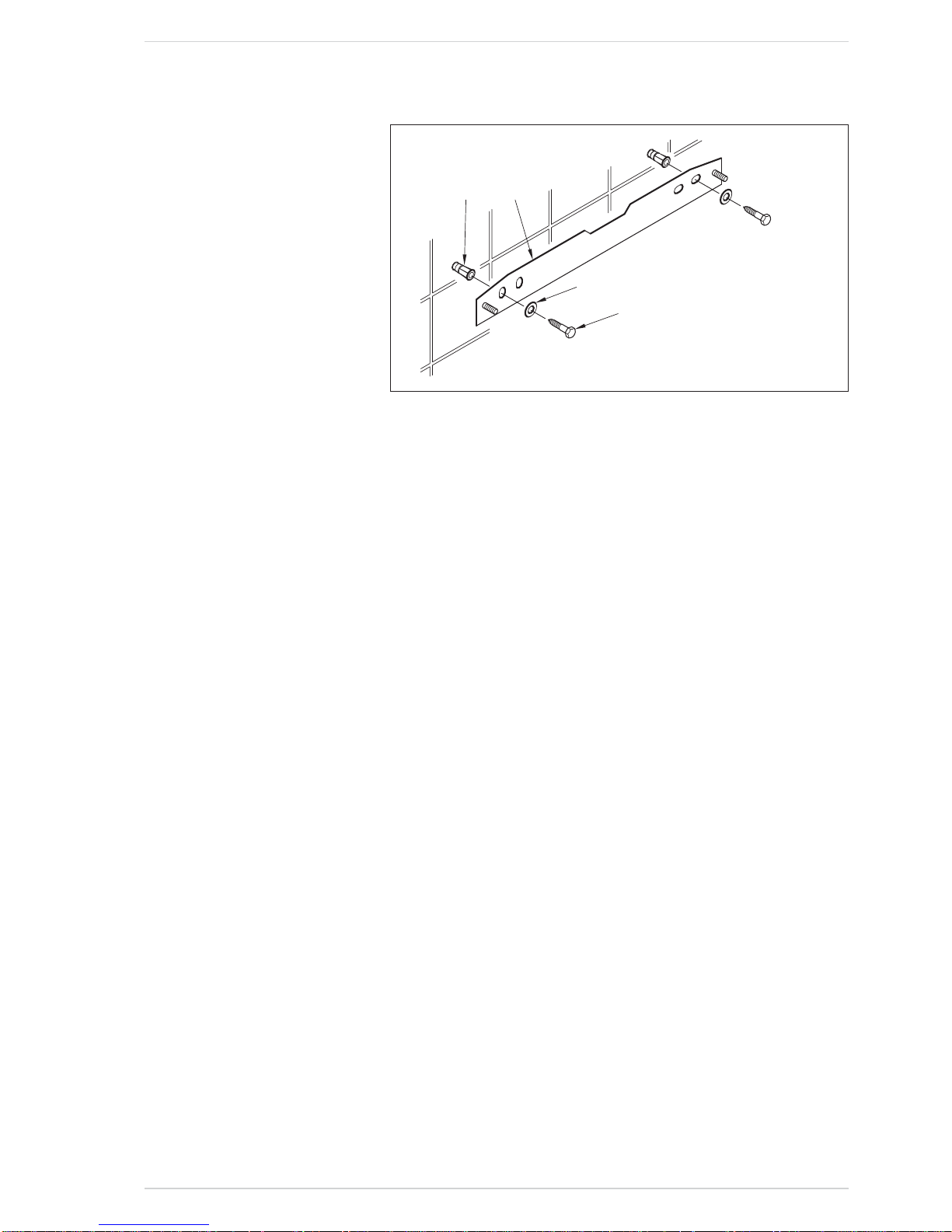
2.2 FIXING THE WALL
MOUNTING BRACKET (fig. 4)
– Mark the position of the two wall
mounting bracket fixing holes and the
flue/air duct hole on the appropriate
wall(s).
– Drill the two fixing holes using a 10
mm masonry drill and fit the plastic
plugs provided.
– Accurately measure the wall thickness,
and note this dimension for later use.
– Secure the wall mounting bracket in
position using the screws provided.
Ensure that it is the correct way up,
as indicated in fig. 4.
2.3 CONNECTING UP SYSTEM
Before connecting the boiler it is
recommended that the system be
flushed in accordance to BS 7593, to
eliminate any foreign bodies that may be
detrimental to the operating efficiency
of the appliance. When connecting up
the boiler the clearances in fig 1 should
be respected.
The boiler is supplied with a valve pack
part number 5184817A. The boiler can be
filled and pressure tested prior to any
electrical supply being connected with
the use of the analogue pressure gauge.
A safety valve set at 3 bar is fitted to the
appliance, the discharge pipe provided
should be extended to terminate safely
away from the appliance and where
a discharge would not cause damage
to persons or property but would be
detected. The pipe should be a minimum
of 15 mm Ø and should be able to
withstand boiling water, any should
avoid sharp corners or upward pipe
runs where water may be retained.
Gas Connection
The gas connection must be made
using seamless steel or copper pipe.
Where the piping has to pass through
walls, a suitable insulating sleeve must
be provided. When sizing gas piping,
from the meter to the boiler, take into
account both the volume flow rates
(consumption) in m
3
/h and the relative
density of the gas in question. The
sections of the piping making up the
system must be such as to guarantee
a supply of gas sufficient to cover the
maximum demand, limiting pressure
loss between the gas meter and any
apparatus being used to not greater
than 1.0 mbar for family II gases (natural
gas). An adhesive data badge is sited
inside the front panel; it contains all the
technical data identifying the boiler and
the type of gas for which the boiler is
arranged.
2.3.1 Connection of condensation
water trap
To ensure safe disposal of the condensate
produced by the flue gases, reference
should be made to BS6798:2009.
The boiler incorporates a condensate
trap which has a seal of 75 mm, therefore
no additional trap is required. The
advised method of connection to the
condensate trap is by using 20 mm
overflow pipe with a socket attached to
cover the condensate trap connection.
The condensate should ideally be
discharged internally into an internal
waste pipe(washing machine/sink
waste) or a soil pipe to avoid the risk
of freezing.
External pipe runs should be avoided, but
if it is necessary, the pipework should be
at least 32mm and protected from the risc
of freezing with a waterproof insulation
and the length kept to a minimum and
not exceeding 3 m. termination should
be into an external gully or purpose
made soakaway.
NOTE: All pipework must have a
continuous fall from the boiler and must
be resistant to corrosion by condensate,
copper or steel is NOT suitable.
It should be noted that the connection
of a condensate pipe to a drain may
be subject to local building control
requirements.
2.3.2 Dealing with condensate
See APPENDIX A for guidance on the
disposal of condensate.
2.3.3 Requirements for sealed water
systems (fig. 5)
The heating system design should be
based on the following information:
a) The available pump head is given in
fig. 14.
b) The burner starts if the system
pressure is sufficient to operate the
pressure switch.
c) The appliance is equipped with an
internal by-pass that operates with
system heads (H) greater than 3
m. The maximum flow through
the by-pass is about 300 l/h. If
thermostatic radiator valves are to
be installed, at least one radiator
should be without a thermostatic
valve (usually the bathroom radiator
or the radiator in the room containing
2 INSTALLATION
10
12
3
4
KEY
1 Wall mounting bracket
2 Plastic wall plug (2 Off)
3 Woodscrew (2 Off)
4 Washer (2 Off)
Fig. 4
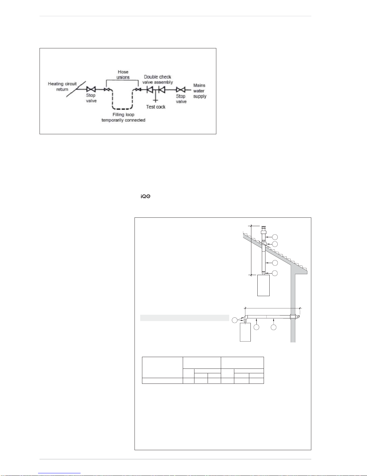
the room thermostat).
d) A sealed system must only be filled by
a competent person using a method
similar to that shown in fig. 5. The
system design should incorporate
the connections appropriate to one
of these methods.
e) It is most important that the boiler is
not allowed to ignite until it and the
heating system is filled.
Ensure that the electrical supply to
the boiler is turned off. Open the auto
air vent, 17 fig 3. Fill the system to
approximately 1.5 bar.
Use the manual air vent located on
the uppermost connection to the
primary heat exchanger (item 8
fig. 3) to release any air retained,
and ensure that all the radiators are
vented. Top up the system pressure
to 1.5 bar. Turn on the power supply
to the boiler and put the boiler in the
Summer mode.
While in the Summer mode, adjust
the heating flow temperature to its
minimum 20 degrees. Put the boiler
into the Winter mode and allow it to
ignite. Run the boiler in this mode for
approximately 30 minutes, regularly
checking that trapped any air is
released. and gradually increasing
the flow temperature to 60 degrees.
When inhibitor is added repeat
this procedure with the initial flow
temperature at 20 degrees. The flow
temperature should then be set to
the desired value.
NOTE: If the domestic water supply is
metered, or should a water meter be
added at a later time, a small expansion
vessel should be included on the
Domestic hot water pipework.
2.4 CHARACTERISTICS
OF FEEDWATER
– All recirculatory systems will
be subject to corrosion unless an
appropriate water treatment is
applied.
This means that the efficiency of the
system will deteriorate as corrosion
sludge accumulates within the
system, risking damage to pump and
valves, boiler noise and circulation
problems.
– For optimum performance after
installation this boiler and its
associated central heating system
must be flushed in accordance with
the guidelines given in BS 7593
“Treatment of water in domestic hot
water central heating systems”.
recommend only the use of
FERNOX products for the flushing
and final treatment of the system
water.
This is particularly important in hard
water areas.
Artificially softened water must not
be used to fill the heating system.
– It is important to check the inhibitor
concentration after installation,
system modification and at every
service in accordance with the
manufacturer’s instructions (Test
kits are available from inhibitor
stockists).
FLUES INSTALLATION MUST COMPLY
WITH THE CURRENT VERSION OF
BS5440.
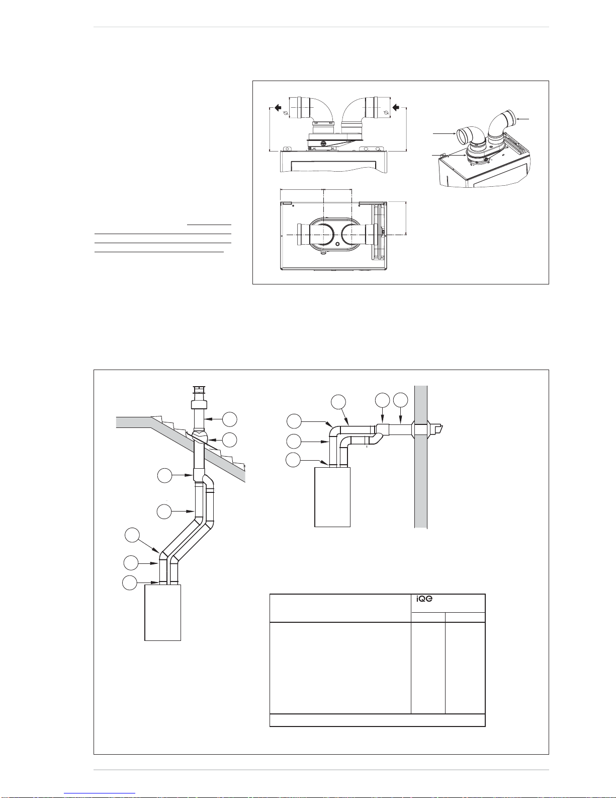
2.5 INSTALLATION COAXIAL DUCT
ø 60/100 - ø 80/125 (fig. 6)
The coaxial suction and discharge pipes
are supplied in a special kit (that can
be purchased separately) along with
assembly instructions.
The diagrams of fig. 6 illustrate some
examples of different types of fluing
options allowed and the maximum
lengths that can be reached.
C33
6
5
3
2
H (m)
C13
1
2
1
L (m)
H (Horizontal) m
V (Vertical) m
METHOD OF FILLING A SEALED SYSTEM
Fig. 5
11
Model Length of pipe Length of pipe
ø 60/100 ø 80/125
V V
H Min Max H Min Max
iQE COMFORT 30 5 m 1.3 m 7 m 10 m 1.2 m 13 m
LIST OF ø 60/100 ACCESSORIES
1 Coaxial duct kit L. 790
code 8096270
2a Extension L. 1000 code 8096160
2b Extension L. 500 code 8096161
3 Vertical extension L. 140
with coupling code 8086960
5 Tile for joint code 8091350
6 Terminal for roof exit L. 1285
code 8091250
LIST OF ø 80/125 ACCESSORIES
1 Coaxial duct kit L. 785 code 8096271
2a Extension L. 1000 code 8096162
2b Extension L. 500 code 8096163
3 Adapter for ø 80/125 code 8093160
5 Tile for joint code 8091350
6 Terminal for roof exit L. 1285
code 80912150
IMPORTANT:
– The insertion of each additional 90° bend
with a diameter of 60/100 (code 8095860)
reduces the available section by 1.5 meters.
– The insertion of each additional 90° bend
with a diameter of 80/125 (code 8095861)
reduces the available section by 2 meters.
– Each additional 45° curve installed a
diameter of 60/100 (code 8095960)
reduces the available length by 1.0 metres.
– Each additional 45° curve installed a
diameter of 80/125 (code 8095961) reduces
the available length by 1.0 metres.
HORIZONTAL FLUES MUST BE LEVEL
NOTE: Before connecting accessories, it is
always advisable to lubricate the internal part
of the gaskets with silicon products. Avoid
using oils and greases.
Fig. 6
2.6 INSTALLATION
OF SEPARATE
DUCTS ø 80 (fig. 7)
The kit with dedicated pipes enables to
separate the exhaust fumes pipes from
the air suction pipes (fig. 7):
– for ø 80 pipes, adaptor code 8093070
is available upon request.
The maximum overall length, resulting
from the sum of all the suction and
discharge pipes, is determined by the
load losses of the single connected
accessories and should not exceed 15
mm H2O (version 25-30) (ATTENTION:
the total length of each pipe should not
exceed 50 m, even if the total loss is
below the maximum applicable loss.)
See Table 3 for information on the load
losses of single accessories (fig. 8).
2.6.1 Separate ducts kit (fig. 8)
The diagrams of Figure 8 show a some
of examples of the permitted exhausts
configurations.
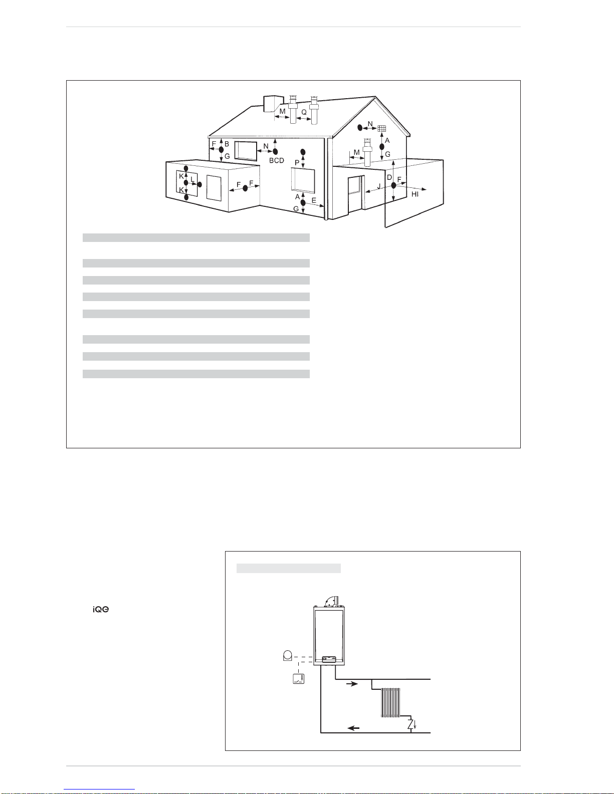
2.7 POSITIONING THE
OUTLET TERMINALS (fig. 9)
The outlet terminals for forced-draught
appliances may be located in the external
perimeter walls of the building.
To provide some indications of possible
solutions, Table 4 gives the minimum
distances to be observed, with reference
to the type of building shown in fig. 9.
12 0
18 3
13 9
18 5
18 5
80
80
1
2
3
CS
CA
130 (vers. HE 35)
Fig. 7
KEY
1 Adaptor with vent
2 Air intake
3 Exhaust
CA Inlet
CS Outlet
12
9
C
C33
11
10
3
1
1
3
3
7
3
12
12
12
Fig. 8
NOTE
Before connecting accessories, it is always advisable to
lubricate the internal part of the gaskets with silicon products. Avoid using oils and greases.
C13
3
2
3
1
14
12
13
12
TABLE 3 COMFORT 30
Load loss - mm H
2
O
Inlet Exhaust
1 Air/smoke divider, code 8093070 0 0
2 90° bend, code 8077453 0.25 0.30
3a Extension 80mm L. 1000, code 8077352 0.20 0.20
3b Extension 80mm L. 500, code 8077353 0.10 0.10
7 45° bend, code 8077454 0.20 0.20
9 Inlet/ exhaust fitting, code 8091450 -- - 10 Articulated tile, code 8091350 -- - 11 Vertical roof terminal, code 8091250 * 1.10 0.15
13 Inlet/ exhaust fitting, code 8091450 -- --
14 Coaxial Terminal, code 8096271 * 1.10 0.15
* This loss includes the losses with use of item 9 or 13
2.9 ELECTRICAL
CONNECTION
The boiler is supplied with an electric
cable. Should this require replacement,
it must be replaced with one of similar
type and dimensions.
The electric power supply to the boiler
must be 230V - 50Hz single-phase
through a 3 amp fused main switch,
with at least 3 mm spacing between
contacts.
Respect the L and N polarities and the
earth connection.
NOTE:
declines all responsibility
for injury or damage to persons,
animals or property, resulting from the
failure to provide for proper earthing of
the appliance, or incorrect connection
of external controls. Any fault or
component failure due to incorrect
connection of external controls is not
covered in the warranty.
2.9.1 Climatic control option
The boiler is designed for connection to
an external temperature sensor, supplied
on request (code 8094102).
2.9.2 External wired controls
The heating function of the boiler can
be controlled by voltage free signal,
TA, connected to terminals 5 & 6 after
removal of the link.
Description of the letters indicating
the components shown on the system
diagram:
M C.H. flow
R C.H. return
SE External temperature sensor
TA 1-2 Room Thermostat
R
M
SE
TA
CR
EXP
13
– If the terminal discharges into a pathway or passageway
check that combustion products will not cause nuisance
and that the terminal will not obstruct the passageway.
– Where the lowest part of the terminal is fitted less than 2
m (78 in) above ground, above a balcony or above a flat
roof to which people have access, the terminal MUST be
protected by a purpose designed guard.
– Where the terminal is fitted within 850 mm (34 in) of a plas-
tic or painted gutter, or 450 mm (18 in) of painted eaves,
an aluminium shield at least 1,500 mm (59 in) long must be
fitted to the underside of the painted surface.
– The air inlet/outlet flue duct MUST NOT be closer than 10
mm (0.4 in) to combustible material.
– In certain weather conditions the terminal may emit a
plume of steam. This is normal but positions where this
would cause a nuisance should be avoided.
Terminal position Minimum spacing
A Directly below an openable window, air vent
or any other ventilation opening 300 mm 12 in
B Below guttering, drain pipes or soil pipes (*) 75 mm 3 in
C/D Below eaves, balconies or carport roof 200 mm 8 in
E From vertical drain pipes or soil pipes 75 mm 3 in
F From internal or external corners 300 mm 12 in
G Above adjacent ground, roof or balcony level 300 mm 12 in
H From a boundary or surface facing the boiler 600 mm 24 in
I From a terminal facing the terminal 1,200 mm 48 in
J From an opening in the carport
(eg door, window into dwelling) 1,200 mm 48 in
K Vertically from a terminal on the same wall 1,500 mm 60 in
L Horizontally from a terminal on the same wall 300 mm 12 in
M Horizontally from a vertical terminal to a wall 300 mm 12 in
N Horizontally from an openable window or other opening 300 mm 12 in
P Above an openable window or other opening 300 mm 12 in
Q From an adjacent vertical terminal 600 mm 24 in
(*) For condensing boilers this distance can be reduced to 25 mm without effecting
boiler performance, but it will be necessary to protect the surfaces from the effects
of condensate
TABLE 4
Fig. 9
For guidance only, flues should be installed in accordance with BS5440
1 BASIC SYSTEM
SYSTEM WITH A DIRECT ZONE AND ROOM THERMOSTAT AND
EXTERNAL SENSOR (Code 8094102)
14
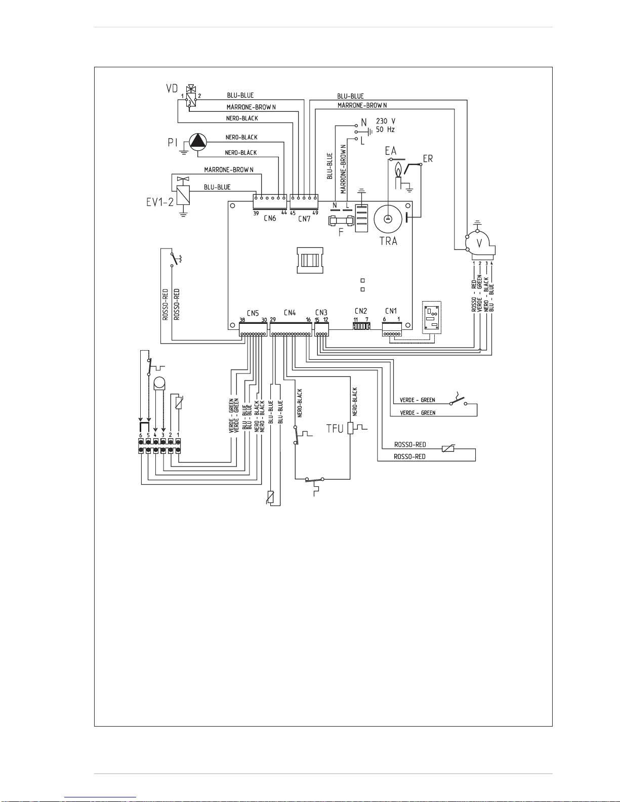
2.10 BOILER ELECTRICAL (fig. 11)
PA (24 VDC)
FL (12 VDC)
SF (3.3 VDC)
SS
(3.3 VDC)
SE (3.3 VDC)
TA (24 VDC)
SM (3.3 VDC)
TS (3.3 VDC)
TL
(3.3 VDC)
EXP
(24 VDC)
Fig. 11
KEY
F Fuse (1.6 AT)
TRA Ignition transformer
PI Pump
V Fan
EA Ignition electrode
ER Ionisation electrode
EV1-2 Gas valve coil
VD Divertor valve
SM C.H. sensor
TS Safety thermostat
TFU Thermal fuse
TL Limit stat
FL D.H.W. flow switch
SF Exhaust temperature sensor
PA Water pressure switch
TA Room thermostat
SE External sensor (optional)
SS D.H.W. sensor
NOTE: Connect a voltage free external room thermostat/programmer (TA) to terminals 5 & 6 after removal of the link.
CONNECTOR SPARE PART CODES:
CN3 code 6319158
CN4 code 6323856
CN5 code 6316253
CN6 code 6323861
CN7 code 6323860

15
3 CHARACTERISTICS
3.1 CONTROL PANEL (fig. 12)
1
2
3
4
1 - DESCRIPTION OF DISPLAY ICONS
SUMMER MODE ICON
WINTER MODE ICON
D.H.W. MODE ICON
HEATING MODE ICON
BURNER LIT ICON
LOCKOUT DUE TO NO
IGNITION/FLAME DETECTION
RESET REQUIRED
MAIN DIGITS
Fig. 12
2 - DESCRIPTION OF CONTROLS
OPERATING MODE/RESET
Press this key repeatedly to step from standby
to summer to winter. The green LED will flash
accompanied by a audible signal, to indicate that
the key has been pressed. Press the key for more
than two seconds to enter standby. RESET is only
available if a re-settable error is signalled.
D.H.W. SET
Press the key to display the D.H.W. temperature
value set
HEATING SET
Press the key to display the heating flow temperature value set (value not realtive to the remote
control)
DECREASE
Pressing this key decreases the value set
INCREASE
Pressing this key increases the value set
3 - LED GREEN
ON = Indicates the presence of electrical voltage.
It switches of momentarily every time the keys are pressed.
It can be disabled by setting PAR 3 = 0.
4 - LED RED
OFF = Normal operation
ON = Boiler error signalled
Flashing when the control panel buttons are pressed inside
the PARAMETERS SECTION.
 Loading...