

IQ CCTV IQR1920D4, IQR1920D8 User Manual
User Manual
Version 1
Touch
Panel
Remote
Access
HD
Resolution
Full HD DVR with HDMI Output,
Real Time 1080P Recording
and Mobile/Internet Access
Models:
IQR1920D4
IQR1920D8
HDMI
Output
1920x1080P
HD

2
Contents
Safety Instructions ……………………………………………………………. 5
Chapter 1. DVR Features ………………………………………………..…… 6
1.1. Features ………………………………………………………. 6
Chapter 2. Overview …………………………………………………………... 7
2.1. Front Panels ………………………………………………….. 7
2.1.1. 4/8 Channel DVR Front Panel …………………….… 7
2.2. Rear Panels ………………………………….……………….. 9
2.2.1. 4/8 Channel DVR Rear Panel ……………………….. 9
2.2.2. RS485/Sensor/Alarm Port Functions ……………….. 10
2.3. 4/8 Channel Remote Controller …………………………….. 10
2.4. Mouse Operation …………………………………………….. 11
Chapter 3. DVR Connection ………………………………………………….. 12
3.1. HDD Installation ……………………………………………… 12
3.2. Camera and Monitor Connection …………………………… 12
Chapter 4. DVR Boot Up ………………………………………………………. 13
4.1. System Initialization ………………………………………….. 13
4.2. Live Interface …………………………………………………. 14
Chapter 5. DVR Menu …………………………………………………………. 16
5.1. Pop Up Menu ………………………………………………… 16
5.2. Main Menu Guide ……………………………………………. 16
5.3. Main Menu ……………………………………………………. 18
5.3.1. Display …………………………………………………. 18
5.3.1.1. Live Mode ………………………………….. 18
5.3.1.2. Output Mode ………………………………. 19
5.3.1.3. Privacy Zone ………………………………. 20
5.3.2. Record Set …………………………………………….. 21
5.3.2.1. Record Parameters ……………………….. 21
5.3.2.2. Schedule …………………………………… 21
5.3.2.3. Main Stream ……………………………….. 22
5.3.3. Search …………………………………………………. 23
5.3.3.1. Record Search …………………………….. 23
5.3.3.2. Channel Select ……………………………. 23
5.3.3.3. Time Axis setup, file clip, zoom in/out ….. 24
5.3.3.4. Event Search ……………………………… 25
5.3.3.5. File Backup …………………………………. 26
5.3.3.5.1. Back-up File Based on Event …. 26
5.3.3.5.2. Back-up File Based on Time ….. 27
5.3.3.5.3. Play Back-up File ……………..... 27
5.3.3.4. Log Search ………………………………..... 28

3
5.3.4. Network …………………………………………………. 29
5.3.4.1. Network Set …………………………………. 29
5.3.4.2. Mobile Set …………………………………… 32
5.3.4.3. Router’s Port Forwarding ………………….. 32
5.3.4.4. Sub Stream …………………………………. 33
5.3.4.5. Email Set ……………………………………. 33
5.3.4.6. DDNS Set …………………………………… 34
5.3.5. System ………………………………………………….. 35
5.3.5.1. HDD Set …………………………………….. 35
5.3.5.2. PTZ Set ……………………………………… 36
5.3.5.3. General ……………………………………… 36
5.3.5.4. Users ………………………………………… 37
5.3.5.5. Information ………………………………….. 38
5.3.6. Advanced ………………………………………………. 39
5.3.6.1. Motion ………………………………….……. 39
5.3.6.2. Alarm Set …………………………………… 40
5.3.6.3. Maintain ……………………………………... 41
5.3.6.4. Event ………………………………………… 42
5.4. Menu Lock …………………………………………………….. 43
5.5. Split Mode …………………………………………………….. 43
5.6. PTZ Control …………………………………………………… 43
5.7. PIP Mode ……………………………………………………… 44
5.8. Record Search ……………………………………………….. 44
5.9. Mute …………………………………………………………… 44
5.10. Manual Record ……………………………………………… 45
5.11. Stop Record …………………………………………………. 45
5.12. Start Sequence .…………………………………………..… 45
5.13. Start Cruise ………………………………………………….. 45
Chapter 6. Web Application ………………………………………………….. 46
6.1. ActiveX Control Download and Installation ……..……..….. 46
6.2. Web Application Manager Log-in ……………………….…. 48
6.3. Live Interface ……………………………………………….… 48
6.3.1. Menu Bar …………………………………………….… 49
6.3.1.1. Live Display ………………………………... 49
6.3.1.2. PTZ Control ………………………….…….. 50
6.3.1.3. Video Control …………………………….… 50
6.3.2. Playback ……………………………………………….. 51
6.3.2.1. Record Search …………………………….. 51
6.3.2.2. Playback Control …………………………... 52
6.3.3. Configuration …………………………………………... 53
6.3.3.1. Display Configuration ……………………… 53
6.3.3.2. Record ………………………………………. 54
6.3.3.3. Network Parameters ………………………. 55
6.3.3.4. System ………………………………………. 58
6.3.3.5. Advanced …………………………………… 60
6.3.4. Local Setting …………………………………………… 63

4
6.3.5. Logout ………………………………………………….. 64
6.4. Mobile Viewing Access Instructions ……………………….. 64
Appendices …………………………………………………………………..… 72
Appendix 1. Operation Function Table …………………………. 72
Appendix 2. Alarm Record Setting ……………………………… 74
Appendix 3. Troubleshooting ……………………………………. 75
Appendix 4. Usage Maintenance ……………………………….. 76
Appendix 5. Accessories ………………………………………… 77

5
Safety Instructions
1. Please read the instruction manual carefully before using the equipment.
2. Please make sure to use the PSU supplied with the DVR.
3. All equipment should be placed in an area away from water and moisture.
4. Do not install the DVR near any heat source, such as radiators, that produce
heat.
5. Please don’t use the equipment near a dusty area or near an intense magnetic field.
6. Before cleaning the equipment, unplug the unit from the wall. Please refrain from
using liquid aerosol cleaners and use a damp, soft cloth.
7. Please make sure to unplug the DVR during a lightning storm
8. Do not place the equipment on an unstable surface.
9. Please do not block any ventilation openings on the DVR.

IQCCTV IQ1920DVR User Manual
6
Chapter 1 DVR Features
ns
1.1 Features:
! H. 264 video compression format: supports 1080P resolution
! G.711 audio compression format
! HD 960H, WD1, WHD1 and WCIF Recording Playback
! Embedded real-time Linux2.6 operation system
! VGA and HDMI Outputs
! Multiple alarm record modes
! Rear USB2.0 ports for back-up, recorder, upgrade and mouse operation
! Backup with USB, network or DVD (Optional)
! Mobile Phone Access
! Multiple language OSD
! Support auto-maintain
Function
Description
Real time
monitoring
Double video output: Monitor, VGA virtual output port or HDMI Output.
Supports net-viewer and MP live surveillance and also supports zoom
in/out, auto sequence and PIP display.
Recording
H.264 video compression format. The recording quality, resolution and
frame rates are adjustable to user’s needs. Multiple recording modes
(Constant, Scheduled, Manual, Alarm, Motion detection and remote record)
Recording
Storage
Supports a 3TB SATA HDD and saves real-time recorded images to HDD.
Playback
Supports DVR single CH and multiple CH Search/Playback of recorded
files.
Backup
DVR backup via USB flash drive, removable drive, Recorder and network.
Alarm Setting
Supports HDD & video input alarm management and external alarm signal
inputs. (8 Channel Only)
Network
Operation
Supports remote surveillance by admin users to increase system security.
Mouse
Operation
Supports Mouse operation for faster menu navigation.
PTZ Control
Supports PTZ camera operations through RS-485.
IQCCTV IQ1920DVR User Manual
7
Chapter 2 Overview
2.1 Front Panels
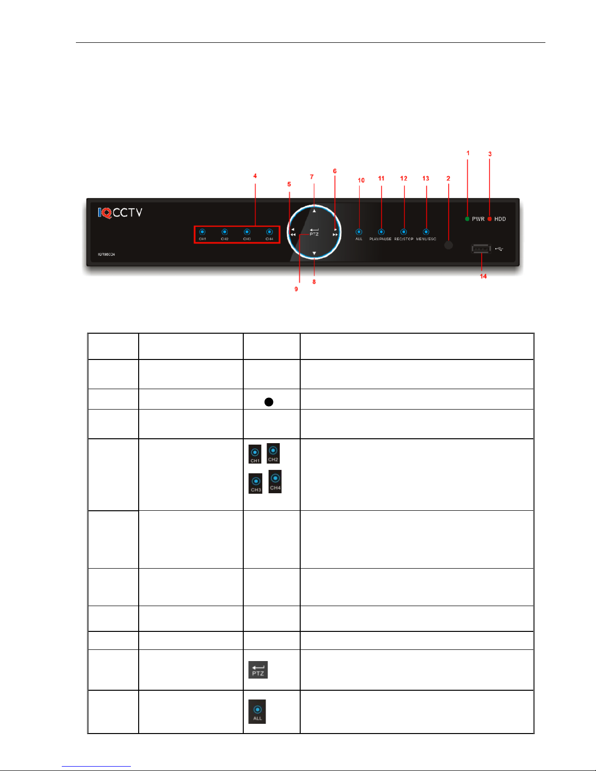
2.1.1. 4/8 Channel DVR Front Panel
Item
Key title or Indicator
Remark
Function & Description
1
Power Indicator
PWR
If the “Green” indicator is on the system is getting
power normally.
2
IR Receiver
Receives IR signal from Remote Controller
3
HDD Indicator
HDD
When the “Red” indicator flashes it means the hard
drive is being read or Recording
4
Channel select:
CH1 CH2 CH3 CH4
CH select key
5
REW Left Key
Move to left; Rewind function;
Decrease PTZ rotation speed and parameter value.
On preview mode, hold the button to switch GUI
operation device
6
FWD
Right Key
Right key, increase PTZ rotation speed and
parameter value and fast forward
7
Up key
Move up
8
Down key
Move down
9
PTZ/Enter
In the Menu, press this key to enter. Not in the menu,
PTZ operation
10
All channel display
Display all channels

IQCCTV IQ1920DVR User Manual
8
11
Play/Pause
Play record file, Pause record file
12
Rec/Stop
Begin record, stop record
13
Menu/ESC
Enter into main menu/exit Menu
14
USB
USB PORT
IQCCTV IQ1920DVR User Manual
9
2.2 Rear Panels
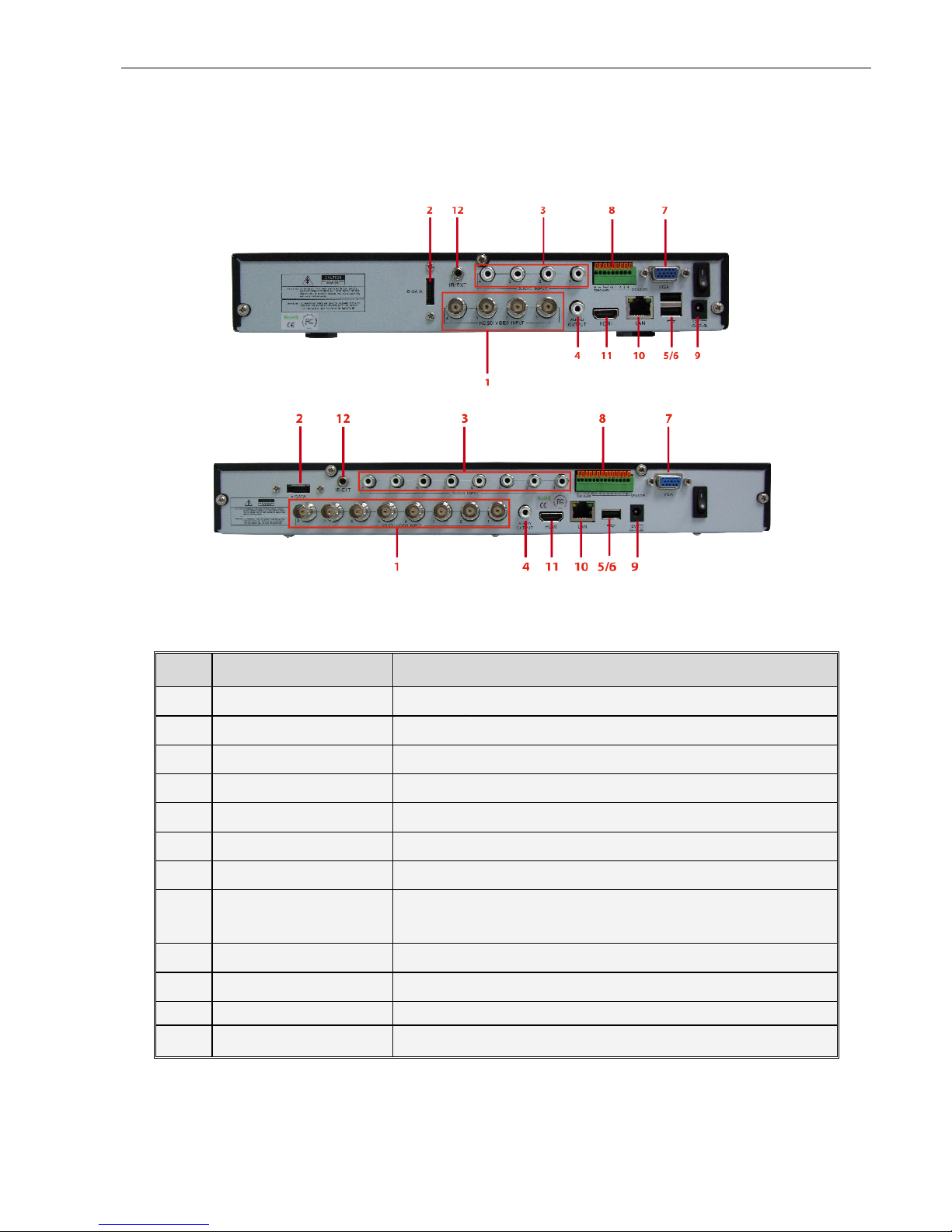
2.2.1. 4/8 Channel DVR Rear Panel
Item
Physical port
Connection method
1
Video input
Connect CH1-4 or 1-8 (Virtual) video input device(BNC
2
e-SATA
Connect e-SATA
3
Audio Input
4/8CH Audio input (RCA interface)
4
Audio Output
Audio output (RCA interface)
5
USB Port
Connect USB device (Flash Drive, Hard Drive and Recorder
6
USB Port
Connect USB mouse
7
VGA Port
Connect to VGA monitor, such as PC monitor (Optional)
8
RS-485/Sensor/Alarm
RS485/Sensor/Alarm interface – Alarm Interface on 8
Channel
9
Power Port
Connect power supply - DC12V 3A
10
Ethernet: Port
Connect LAN, Ethernet (RJ45 interface)
11
HDMI Port
Connect HDMI
12
IR-EXT
IR Extension
IQCCTV IQ1920DVR User Manual
10
2.2.2 RS485/Sensor/Alarm port functions
• Alarm input: Connect [-] port of your sensor to G (GND) pin, and [+] port to channel input
according to the alarm device you purchased.
• Alarm output: Connect to the two ports marked with “out”
• PTZ Port: Connect your camera to RS-485A and RS485B accordingly.
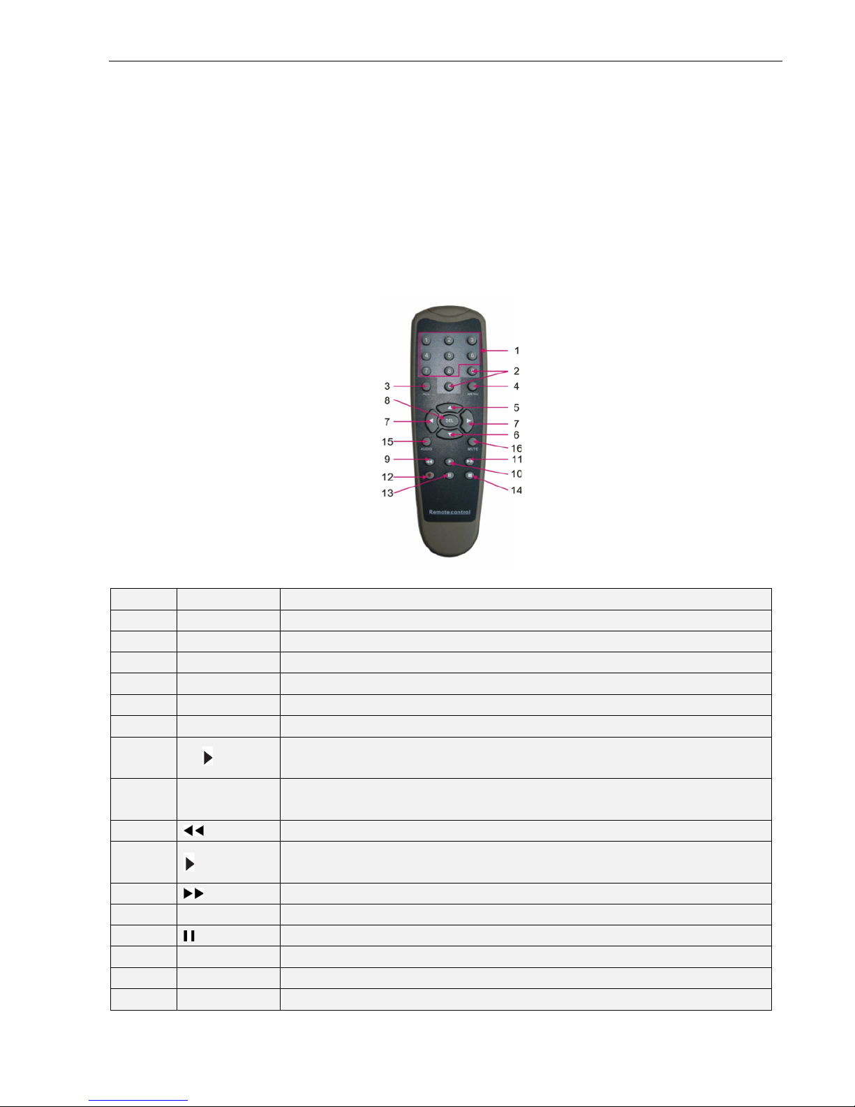
2.3. 4/8 Channel Remote Controller
Item
Key title
Key function
1
1-8
Channel select 1-8; Numeric key
2
9、0
Numeric key; Clicking numeric “0” allow you switch to output device
3
ALL
Multiple display mode
4
Menu
Enter into Main menu/Exit
5 ▲ Up arrow key, Volume adjust
6 ▼ Down arrow key, Volume adjust
7
◄/
Left/Down key,
Decrease/increase parameter value of control bar
8
SEL
Select key/Edit key;
Confirm the selected operation.
9 Rewind key
10 Enter into record search menu;
Play key
11 Forward key
12
●
Record key
13 Pause/Sequence key
14 ■ Stop manual record; stop playing
15
Audio
Testing
16
Mute
Mute on/off

IQCCTV IQ1920DVR User Manual
11
2.4. Mouse Operation
TYPE
Function
Click left key of
Mouse
In menu lock mode - Enter into pop-up menu and click any sub
menu to go into the Log-in window.
In menu unlock mode - Enter into pop-up menu, and then clicking
left key to enter into any sub menu directly.
After entering into main menu, click the left key to enter into any sub
menu. On [Detailed file] menu mode, click the left key to playback one
recording file.
Change the status of check box and motion detection area.
Click the combo box to access pull-down menu. Click left key to stop
dwell time display when dwell time display is activated.
By clicking left key you can adjust the colour control bar and volume
control bar.
Clicking combo box to access pull-down menu
By clicking the left key you can select values in edit boxes or pull-down
menu. Mouse supports special symbols, numeric and character input.
Use instead of [Enter- ] or [Backspace ]
Click right key of
Mouse
In live display mode, clicking right key will display pop-up menu
In the main menu or sub menu mode, clicking right key will exit current
menu.
Double-click Left
key of Mouse
In live display or playback mode, double-clicking left key will
maximize the screen.
Moving Mouse
Select menu item
Sliding Mouse
On motion mode, sliding mouse will select motion area.
On [Colour set] menu mode, sliding the mouse will adjust colour
control bar and volume control bar.

IQCCTV IQ1920DVR User Manual
12
Chapter 3 DVR Connection
3.1 HDD Installation
Caution: Please do not Install or take out hard drive when DVR is running.
HDD Installation
(1) Cut power to the DVR
(2) Unscrew the screws and open DVR upper cover carefully
(3) Insert the Power Cord and data cable into Pin of hard drive securely
(4) Remove the screws on the HDD bracket.
(5) Fix the HDD to the bracket and then fix the bracket with HDD to DVR body
(6) Put the upper cover back carefully and re-attach the screws
Please Note: If the user requires a higher performance HDD, please contact the place of
purchase.
3.2 Camera and Monitor Connection
To connect camera a cable to the BNC video inputs at the rear of the DVR.
To connect the DVR to a monitor via the HDMI/VGA Video output connection.
If the camera is a PTZ speed dome, you can connect the RS485 A & B to the corresponding port
of the DVR (refer to system figuration on Chapter 8).
IQCCTV IQ1920DVR User Manual
13
Chapter 4 DVR Boot Upa4: DVR Boot up
4.1 System Initialization
After powering the DVR and pressing the Power button on the front panel, you will enter into the
system initializing screen shown as below.
After initialization, the setup wizard will begin.
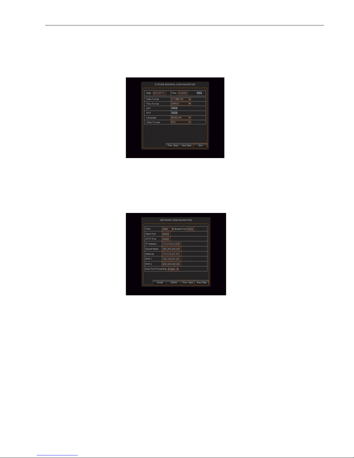
1. HDD Management
As shown in below, the user can set the HDD management, record schedule and network
configuration. In this option, the user can also select the overwrite types and format the HDD.
2. Record Schedule
Set the record schedule with the options shown below.
IQCCTV IQ1920DVR User Manual
14
3. System Configuration
In this section the user can set the time, date DST and NTP as shown below.
4. Network Configuration
Set the network configuration as shown below.
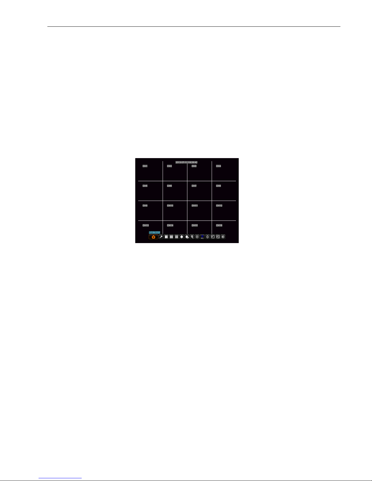
4.2. Live Interface
After finishing setup wizard the system will enter into <Live> screen. The image below shows
the 16-split display defaulted by system. In Live mode, double-click the mouse over the live
image of any channel and the image will be maximized to full screen. By double-clicking again,
the image will be come back to the 16-split display mode. Clicking the right button of the
mouse to enter into the Pop-up Menu.
Once in the Pop-up menu, click the left button of the mouse to select menu items. To exit this
menu, click anywhere outside the menu area.

IQCCTV IQ1920DVR User Manual
15
Please Note: When the internal HDD is not connected or an error occurs, the character “H” will
appear on the first channel of the live screen and accompany buzzer alarm. If you want to close
the buzzer alarm, please enter into [Main menu-Alarm] to set HDD loss and alarm output to “off”.
IQCCTV IQ1920DVR User Manual
16
Chapter 5 DVR Menu
5.1 Pop-up Menu
After finishing system initialization, click the right key of mouse on the main interface mode to
enter into Pop-up Menu. In this menu, the user can change parameter setting and operate the
Main Menu, Multi-Pics, PTZ, Auto Cruise, Zoom in/out, Rec. Search, Manual record, Sequence,
PIP and Vo Switch.
Click the [0] key on the remote controller or hold [Esc] key on the front panel to switch the system
to other output device.
5.2 Main Menu Guide
Please see the following page for the main menu guide.

IQCCTV IQ1920DVR User Manual
17
Search
Record Search
Event Search
Backup
Log search
Display
Output Set
Main Menu
Live set
Privacy Zone
Clip Set
Record Parameters
Schedule
Main Stream
Record
Sub stream
Network Set
Email Set
Mobile(Set(
DDNS Set
Network
Motion Detection
Alarm set
Alarm
Device
PTZ set
Serial Set
HDD
Maintain
Advanced
Event
System
Users
System Information
General
IQCCTV IQ1920DVR User Manual
18
5.3 Main Menu
On <Live> mode, click the [Menu] button on the front panel or Remote controller to enter into the
Main menu interface. In Main Menu mode, you can control device management settings, such as
Display, Record, Network, Search, System and Advanced setting.
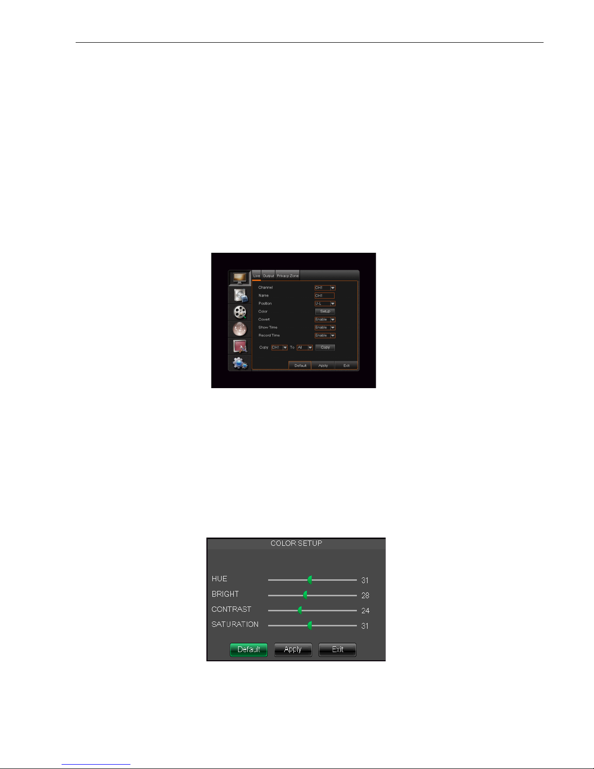
5.3.1. Display
5.3.1.1 Live mode
To enter the Live Mode menu, go to <Main menu "Live> option and enter into the <Display>
setting interface shown as below.
# Channel: Choose which Channel to view
# Name: Change the channel name (allows up to 8 characters)
# Position: Setup the display position of each channel.
# Color: Click [Setup] option to enter into the [Colour setup] interface shown as Picture 5-2.
# Covert: Enable [Live] surveillance screen
# Show time: Enable the system time to appear in the <Live> screen.
# Record time: When the record time is set to “Enable”, you are allowed to record the system
time into the recording history.
# Copy: Copy all data of one channel to any other one
Picture 5-2

IQCCTV IQ1920DVR User Manual
19
1、 Click [APPLY] button on the bottom of the sub-menu windows to accept the changes and
click the [OK] button when prompted to save.
2、 If you want to cancel the modification, click [Exit] button to exit the menu.
3、 When clicking [DEFAULT] button, all the system default values will be reset to default
value.
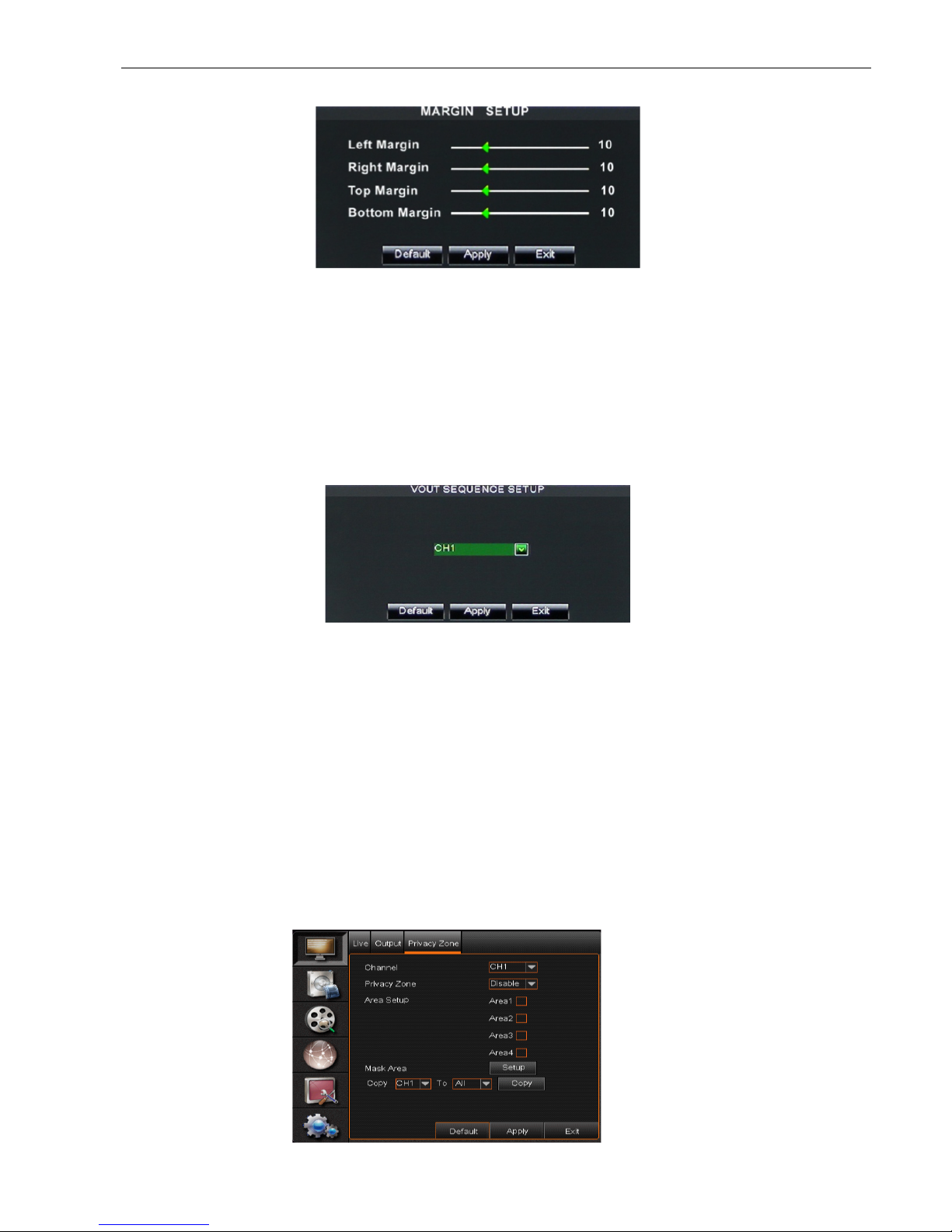
5.3.1.2 Output mode
To enter the output mode menu, go to [Main menu"Display"Output] to enter into the output set
interface shown as shown below.
# Video output: Supports CVBS output Live and Spot mode simultaneously. Live mode is the
main output, and Spot is the auxiliary output.
# CH Sequence: This option is defaulted to “Off” and the sequence time is 5 seconds. The
user can activate the option as desired.
# Rotate time: Allows the user to set the sequence time. Minimum time can be set to 3
seconds.
# VGA/HDMI Resolution: Select VGA or HDMI output, including 800x600, 1024x768,
1280x1024, 1440x900 and 1920 x 1080.
# Display Mode: Live output: display window will include Single, Quad, 9-split and 16-split
mode;
Spot output: Display window will include Single, Quad and 9-split mode.
# Transparency: Adjust the menu’s transparency. Range is 1~128.
# Margin: Adjust the whole screen’s margin. Details operations please refer to the Picture 5-4.
# Volume: Adjust the DVR volume.
IQCCTV IQ1920DVR User Manual
20
Picture 5-4
Click the [Live] button to pop up the interface as shown in Picture 5-5. This allows the user to
perform a channel sequence setting.
Similarly, Click the [Spot output] option and set relative parameters.
5.3.1.3 Privacy Zone
This function allows the user to setup privacy zone parameters, as show in the image below.
Each channel can have up to four privacy zones. Follow below steps to set:
1. Select the area no (Area 1 ~ Area 4)
2. Click [Setup] to adjust position of mask area
3. After finishing position adjust, click right key of mouse to return back [Privacy zone] interface
4. Click [Apply] to save the above setting.
Picture 5-5
IQCCTV IQ1920DVR User Manual
21
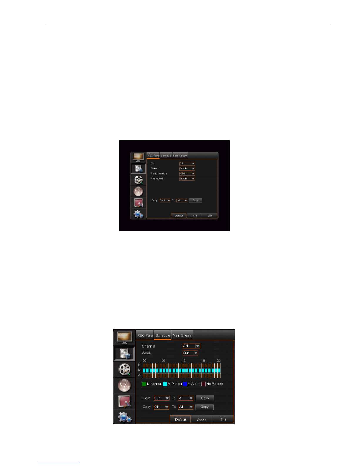
5.3.2 Record set
5.3.2.1 Record parameters
Click [Main menu"Record"Record Para] to enter into the interface shown in the image 5-7
below.
# Channel: Setup the channel desired.
# Record: Set up the record status. Enable/Disable of each channel
# Pack Duration: Indicates the maximum continuous record time (15, 30, 45 and 60 min).
5.3.2.2 Schedule
Click the [Main Menu"Record"Schedule] to enter into the interface as shown below.
The [Channel] option allows the user to select any desired channel.
To setup weekly schedules, check the box of the record status you want (Alarm, General, or No
Record) and then click on each box in the schedule time line that you want. Click the [Copy – To]
pull-down menus and Copy button to copy settings from one day to any other day.
Picture 5-7
IQCCTV IQ1920DVR User Manual
22
Once the desired time schedule has been selected, click the [APPLY] button to save the options.
To restore to factory default settings, click the [DEFAULT] button.
Please Note: Under the <record> menu and <search> menu, original color stands for no record,
“Red” stands for alarm record, “yellow” stands for Motion record and “Green” stands for normal
record.
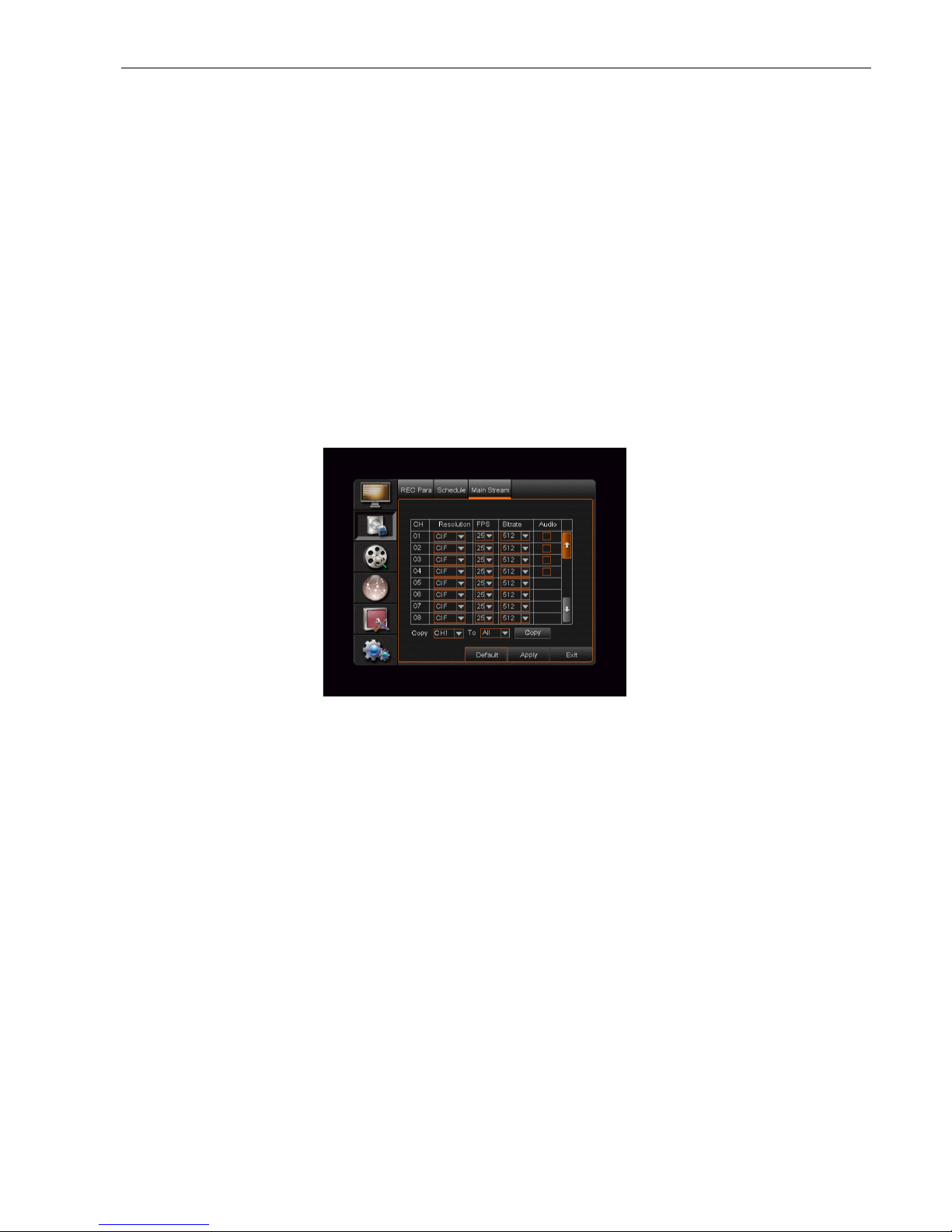
5.3.2.3 Main Stream
Go to [Main menu"Record"Main Stream] to enter into the interface as shown below.
To go to the settings menu in the HD-SDI DVRs, enter Main Menu→Record→Main stream to
enter into the interface.
# Resolution: Supports 1080P. Save and exit the main menu. The system will restart when
the settings are saved.
# Record Resolution: Supports 1080P
# Frame Rate: PAL: 1-25 fps, NTSC:1-30 fps
# Bit Rate: Local record bit rate. The user can select the relative value by pull-down menu
# Audio: When selecting the Audio option, the system will record video images with audio
simultaneously.

IQCCTV IQ1920DVR User Manual
23
5.3.3 Search
5.3.3.1 Record Search
Click the [Main Menu"Search"Record Search] to enter into the interface as shown on the
following page.
# Channel: Select the channel(s) that you desire to search.
# Date Search: In the Video Search screen, the user can search for all the records in a
specific date. To execute a video search, highlight and select the date numeric field and then
click the desired time of a recorded even on that specific date.
# Time Search: In the <Search screen>, the user can search for a specific date and time for a
recording and view it in Playback mode. This is useful for hunting a specific recording of an
incident if you know the date and time it occurred.
# File List: Click the [File List] button to enter into the [Event Search] screen shown. The video
records for the time you have chosen will appear in the screen.
# Playback Mode: You can use the Playback Control bar to operate the Fast Forward (X2, X4
and X8), Slow play (1/2, 1/4 and 1/8 speed), Play, Pause/Frame, Rewind(X2, X4 and X8).
When ending the playback, the DVR will return back to previous menu shown.
# Play control Bar: The play control bar will display current playing processing. When the
user clicks any time at the control bar and this point have not any record file, the system will
auto return back to previous menu.
5.3.3.2 Channel Select
Then tick-select the channel you want to playback; and click [Play] button to enter into the
playback mode as shown below.
IQCCTV IQ1920DVR User Manual
24
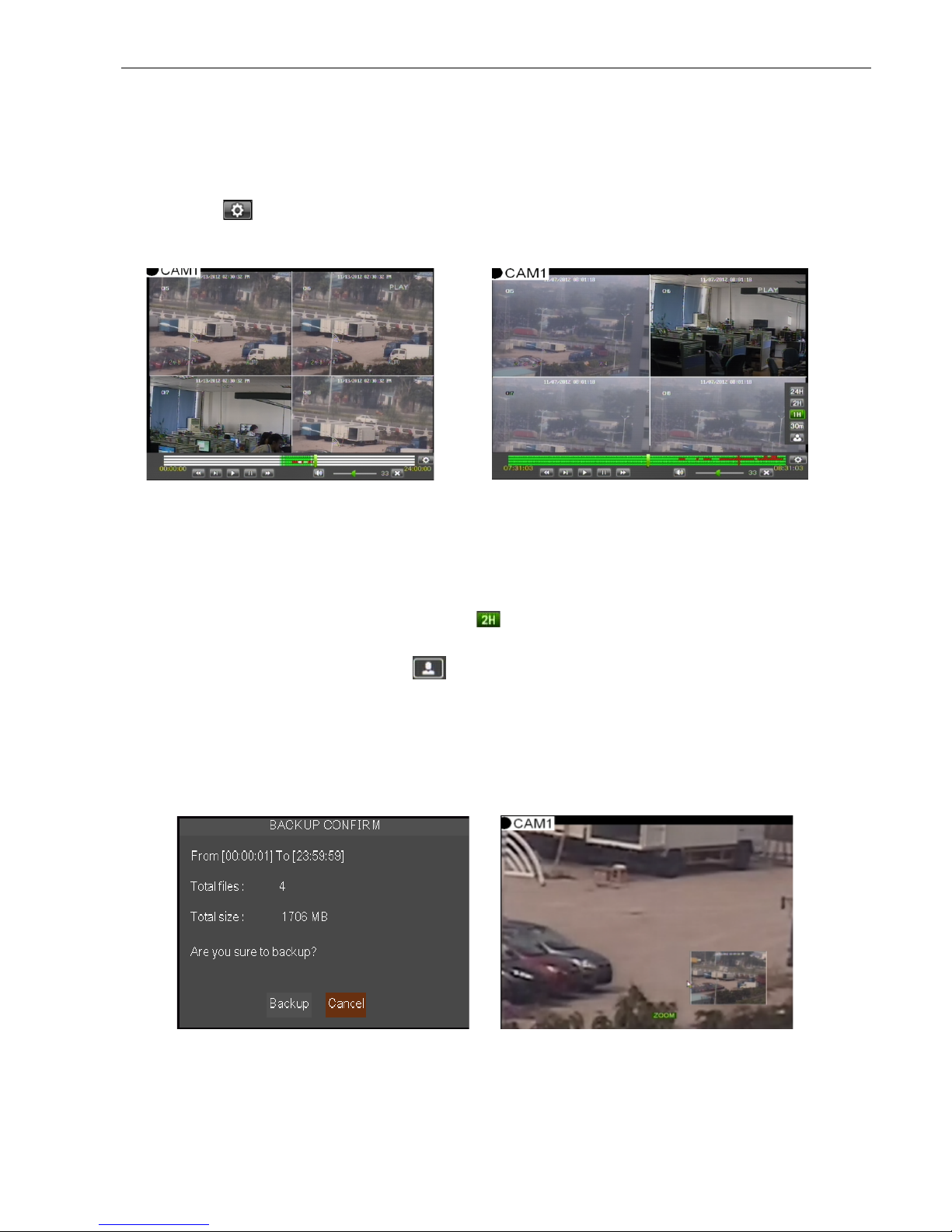
5.3.3.3 Time Axis setup, file clip and zoom in/out
1) The DVR supports the processing control bar function when playing back record files as
shown in Picture 5-12 (Up to 4 CH is available).
2) Click [ ] icon beside the processing bar to pop up the interface shown as Picture 5-13.
Time Axis: Defaulted to 24hours. The user can select 2hours, 1hour, 30 minutes or
user-defined. The detailed operation is as follows:
(1)Fixed time axis: If you select the [ ] option, the processing control bar will cover
two-hours of video content.
(2)User-defined: Select the [ ]option and move the cursor to processing bar to
select start time and/or end time. Now, the whole time axis equals the time of
recording you just selected.
Record Clip and backup function and Zoom in/out function:
Picture 5-12
Picture 5-13
Picture 5-14
Picture 5-15
 Loading...