

IQaudIO PI-DAC+, PI-DIGIAMP+, PI-AMP+ User Manual

IQaudIO
User Guide v20
This document covers the installation, software configuration and
usage of IQaudIO audio cards for the Raspberry Pi A+, B+, RPi2, PiZero and Raspberry Pi 3.
If you would like to see additional information within this document please email us at
info@iqaudio.com
IQaudIO'Limited,'Company'No:'09461908'
For those who just need to know what setting should
be applied to /boot/config.txt in order to load the
IQaudIO device drivers —> Just jump to section 9

IQaudIO user instructions
Contents
1)
Overview
2)
The Pi-DAC+
3)
The Pi-DigiAMP+
4)
The Pi-AMP+
5)
Connecting the Pi-DAC+ to your Raspberry Pi
6)
Connecting the Pi-DigiAMP+ to your Raspberry Pi
7)
Connecting the Pi-AMP+ to your Pi-DAC+
8)
Building the Raspberry Pi and IQaudIO sound cards into your Pi-CASE+
9)
Configuring Raspbian to include sound card support
10)
Checking audio is working through the IQaudIO sound card
11)
Advanced troubleshooting
12)
Controlling the Pi-AMP+ or Pi-DigiAMP+’s Mute / Un-mute
13)
Common Linux distribution configurations (and ALSA H/W volume control name)
14)
Adding the optional PIN headers to the Pi-DAC+
15)
Advanced hardware information
16)
RPi2/3 and external USB devices
17)
Adding a Rotary Encoder (Physical volume control)
18)
Adding an IR (Remote Control) Sensor
19)
Sonic_Pi and IQaudIO
20)
Storing alsamixer settings
21)
Disabling the standard Raspberry Pi On-Board Audio
v20' ' ''''' 19-Aug-2016'2

1)
Overview
The full range of IQaudIO sound cards and accessories are available directly from IQaudIO Limited
(www.iqaudio.com) or through various Worldwide distribution channels. Please note that although
most distributors of our products supply the same optional extras such as PCB standoffs / optional
pin headers etc., not all of those selling our products do. If your distributor doesn’t include these items
then you can either source them yourself or purchase them from us directly for a small charge.
Useful Data:
o
Screws etc. are all m2.5
o
PCB standoffs (for Pi-CASE) are 5mm male / female
o
PCB standoffs (for Pi to IQaudIO products) are 12mm female / female
o
PCB standoffs (for Pi-AMP to Pi-DAC) are 12mm female / male
o
PCB standoffs (for the official Raspberry Pi 7” display) are 5mm male / female*
o
The Pi-DAC+ 40way header is made up of a
▪
10way dual straight pin header
▪
30way right angled pin header
o
The IR header on Pi-DAC+ will take a standard Vishay TSOP4838 IR receiver.
o
The rotary encoders we have used and tested are the ALPHA 3 pin Rotary Encoder
RE160F-40E3-20A-24P, the ALPS EC12E2430804 (RS:'729-5848), the Bourns ECW0J-
B24-AC0006L (RS: 263-2839)
o
The Power Barrel for Pi-AMP+ & Pi-DigiAMP+ is 2.5mmID, 5.5mmOD, 11mm
o
Both Pi-AMP+ & Pi-DigiAMP+ are designed to operate with a 15v 3amp to 19v supply such
as the XPPower VEC65US19 or similar
o
The JST connector used on the Pi-AMP+ and Pi-DigiAMP+ is JST, EH series, 2-pin, 2.5mm
pitch, 3A
o
The Screw Terminals used on the Pi-AMP+ and Pi-DigiAMP+ will accept wires of between
14 ~ 26 AWG (wire of max 1.6mm in diameter)
*These'are'not'supplied'with'the'Pi-DAC+'or'Pi-DigiAMP+,'they'are'available'as'part'of'the'accessory'pack'on'www.iqaudio.com'
v20' ' ''''' 19-Aug-2016'3
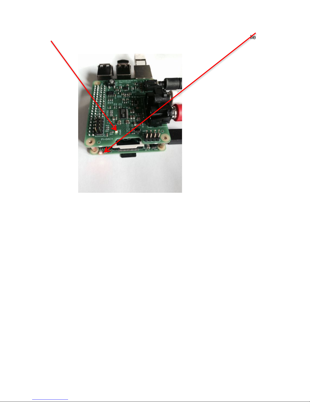
2)
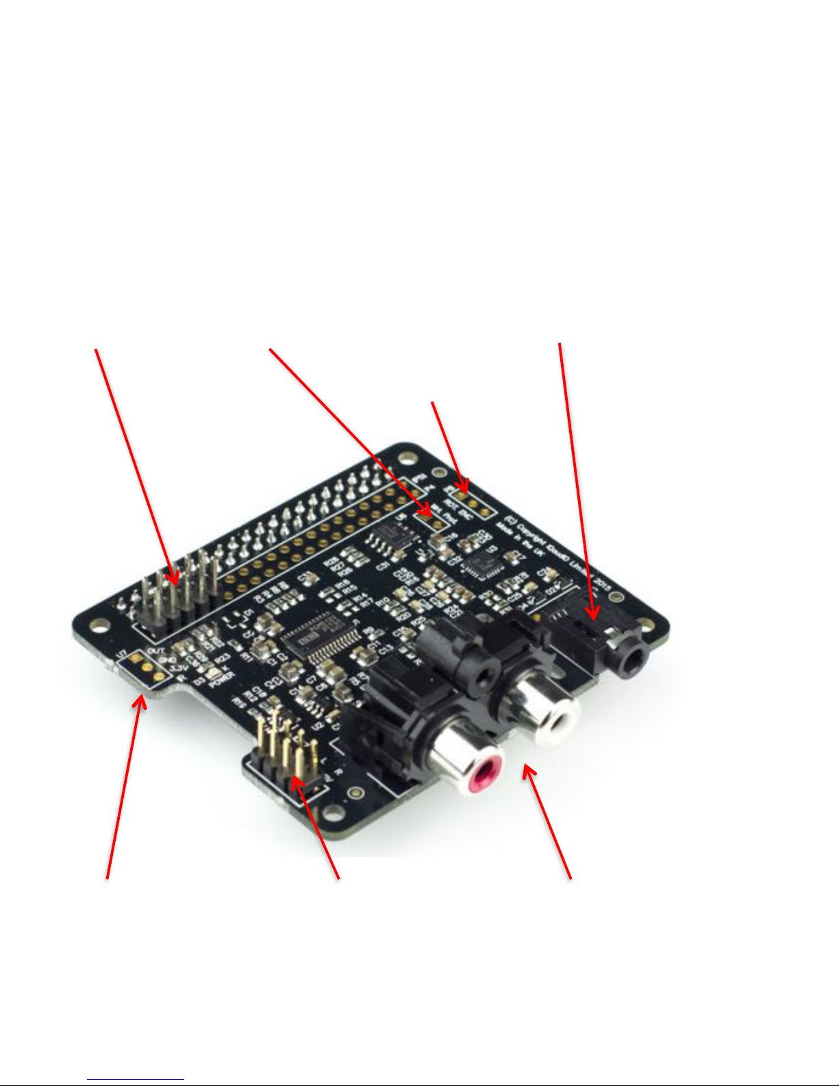
The Pi-DAC+
The Pi-DAC+ is a fully HAT compliant add-on accessory for the Raspberry Pi A+/B+/Pi2.
The Pi-DAC+ takes the digital audio signals (I2S) from the Raspberry Pi and through the onboard
Texas Instruments PCM5122 DAC delivers variable output (hardware volume control) analog audio to
the Pi-DAC+’s Phono connectors. The PI-DAC+ also, via the Texas Instruments TPA6133A
headphone amp, supports the direct use of headphones via the Pi-DAC+’s 3.5mm audio jack.
The Pi-DAC+ can be connected to the Raspberry Pi’s 40way pin header without any additional
soldering.
Component selection and track layout have been in the forefront of our design to ensure noise
immunity and best possible audio playback with the Pi-DAC+.
Pi-AMP+ Power delivery HAT EEPROM Write Enable Headphone Socket
Rotary Encoder Header
IR Header Pi-DAC+ Audio out (for Pi-AMP+) Phono Connectors
v20' ' ''''' 19-Aug-2016'4

3)
The Pi-DigiAMP+
The Pi-DigiAMP+ is a fully HAT compliant add-on accessory for the Raspberry Pi.
The Pi-DigiAMP+ takes the digital audio signals (I2S) from the Raspberry Pi and through the onboard
Texas Instruments TAS5756M PowerDAC delivers direct connection to stereo speakers at up to
2x35w with variable output. Adjustable gain (+20db or +26db) is selectable by a pin header P7 (not
shown below). Only remove and set this when NO POWER IS APPLIED.
The Pi-DigiAMP+ can be connected to the Raspberry Pi A+/B+/RPi2’s 40way pin header without any
additional soldering. The Pi-DigiAMP+ requires a 12-19volt power source to operate. Power should
be applied via the Pi-DigiAMP+’s standard barrel connector or the two pin JST socket provided.
The Pi-DigiAMP+, when powered, has been designed to provide power to the Raspberry Pi and PiDigiAMP+ combination safely. You can continue to use your Pi devices without risk of damage. The
Pi-AMP+ is by default muted at power on (mute LED lit). Mute state / LED is under software control
(Raspberry Pi GPIO22). Component selection and track layout have been in the forefront of our
design to ensure noise immunity and best possible audio playback / experience with the Pi-DigiAMP
+.
Power LED Mute LED GPIO Header
!
15v Power In Speaker Terminals
v20' ' ''''' 19-Aug-2016'5
4)
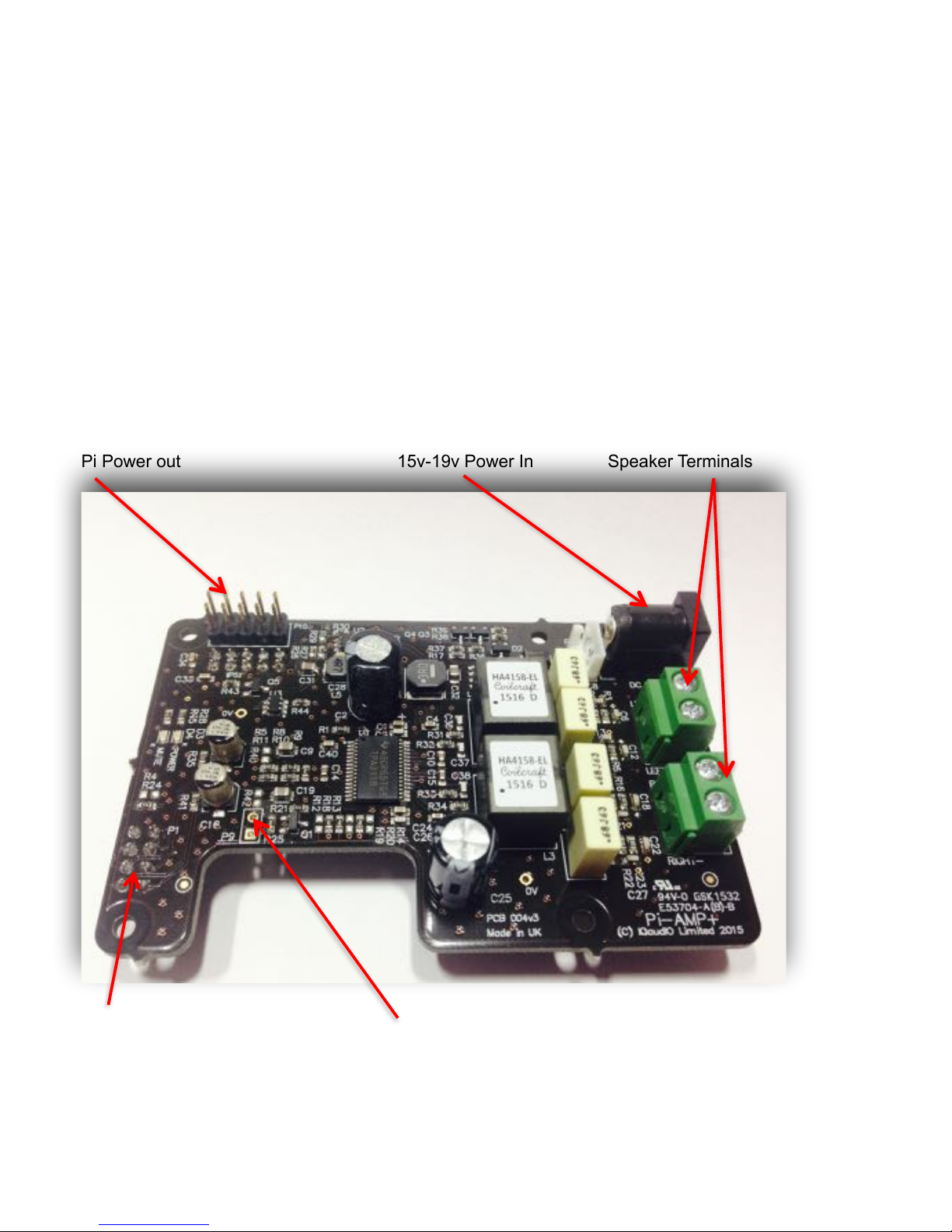
The Pi-AMP+
The Pi-AMP+ is an add-on accessory for the Pi-DAC+ and Raspberry Pi.
The Pi-AMP+ takes the variable output analog audio from the Pi-DAC+ and through the onboard
Texas Instruments TPA3118D2 Class D amplifier delivers audio to the Pi-AMP+’s speaker terminals
delivering up to 2x35w@19v input.
The Pi-AMP+ requires a 12–19volt power source to operate. Power should be applied via the Pi-AMP
+’s standard barrel connector or the two pin JST socket provided.
The Pi-AMP+, when powered, has been designed to provide power to the Raspberry Pi / Pi-DAC+
and Pi-AMP+ combination safely. You can continue to use your Pi devices without risk of damage. As
with the Pi-DAC+, we’ve focused on the components selected and the attention to audio performance
during PCB layout when developing the Pi-AMP+.
The Pi-AMP+ is by default muted at power on (mute LED lit). Mute state / LED is under software
control (Raspberry Pi GPIO22) but mute may be overridden by shorting the Pi-AMP+’s P9 pins with a
suitable jumper – note the mute LED will remain lit if P9 is shorted.
Pi Power out 15v-19v Power In Speaker Terminals
Audio In (from Pi-DAC+) Mute Override (P9)!
v20' ' ''''' 19-Aug-2016'6
5)
Connecting the Pi-DAC+ to your Raspberry Pi
WARNING: PLEASE ENSURE ALL CABLES ARE DISCONNECTED FROM THE Pi-DAC+ AND THE
RASPBERRY PI BEFORE ATTEMPTING THIS PROCEDURE.
The Pi-DAC+ can be connected to the Raspberry Pi’s 40way pin header without any additional
soldering.
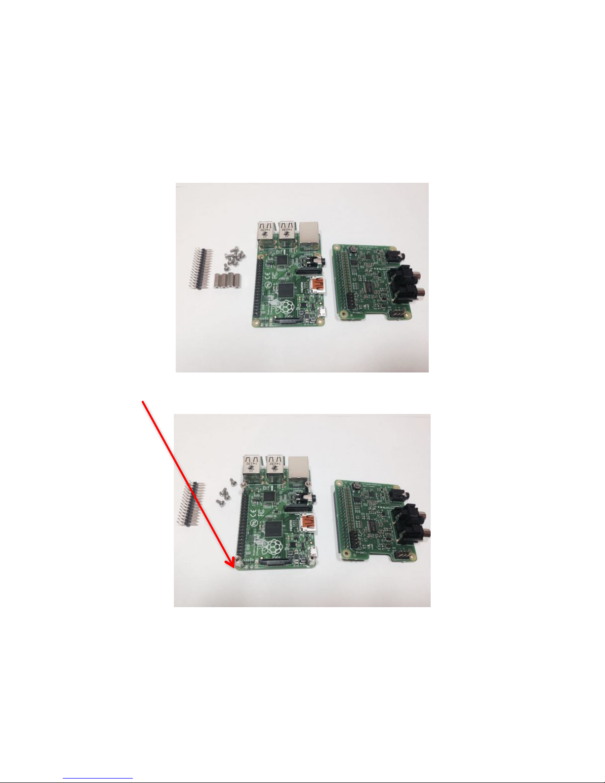
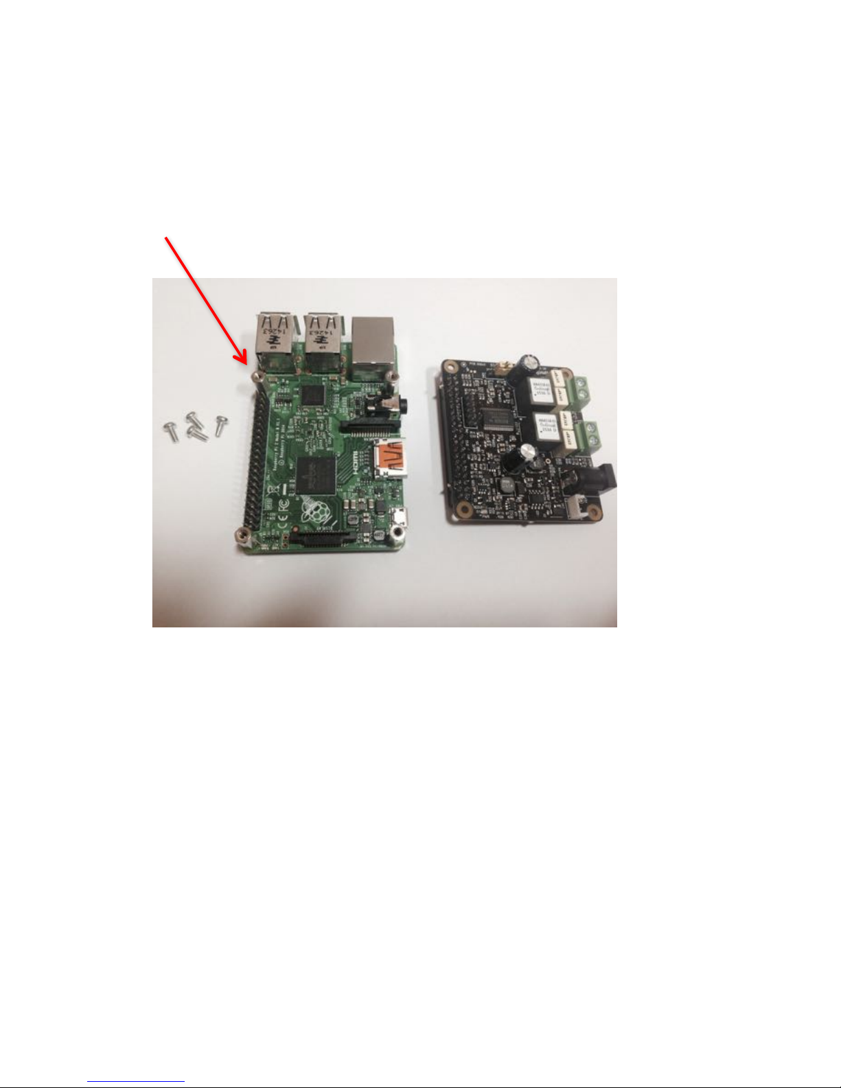
The Pi-DAC+ is normally supplied* along with 4x 12mm PCB spacers and 8x M2.5 screws. You may
want to use a 30way right-angled I/O pin header (only needed if you wish to use the exposed
Raspberry Pi GPIO).
!
The spacers should be screwed (finger tight only) to the Raspberry Pi before adding the Pi-DAC+.
!
v20' ' ''''' 19-Aug-2016'7
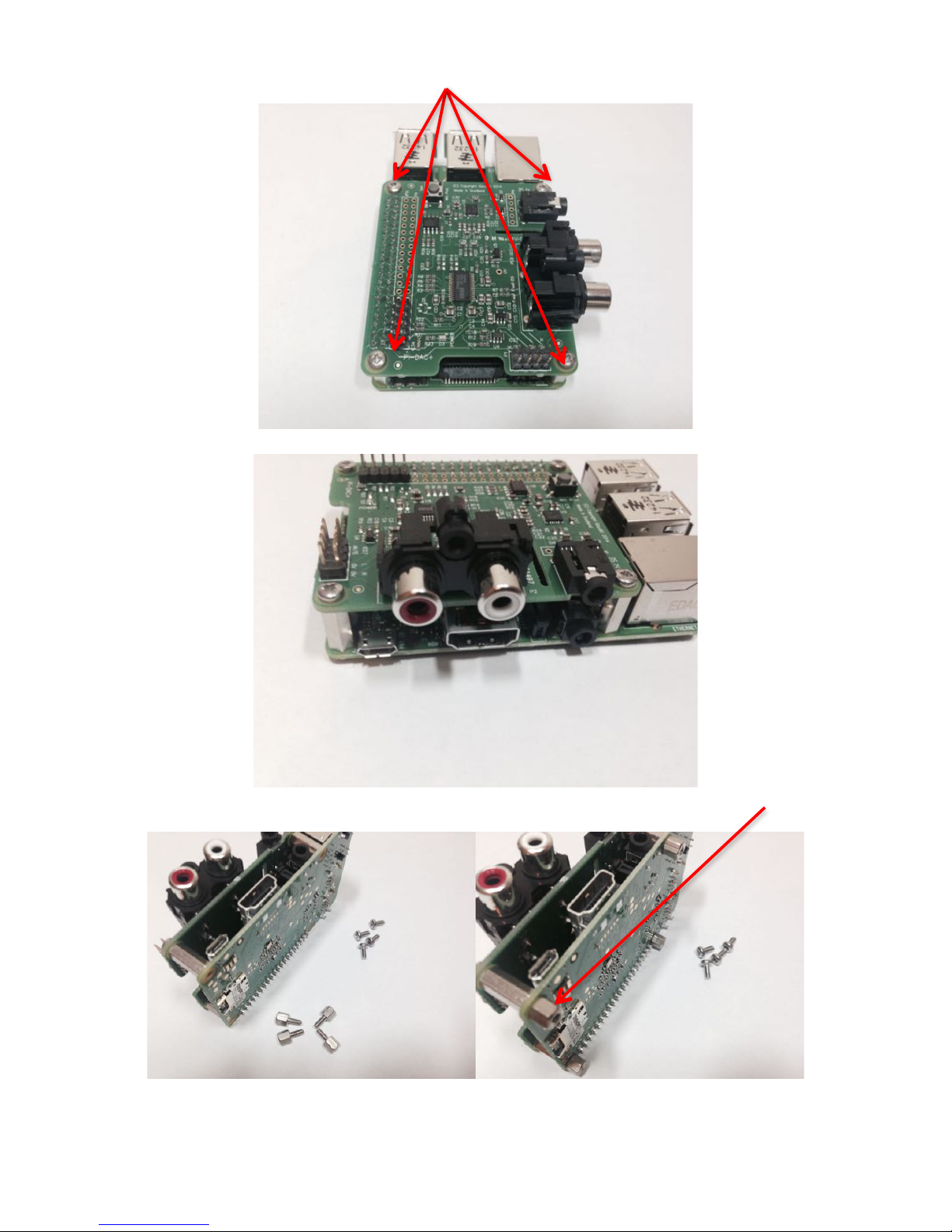
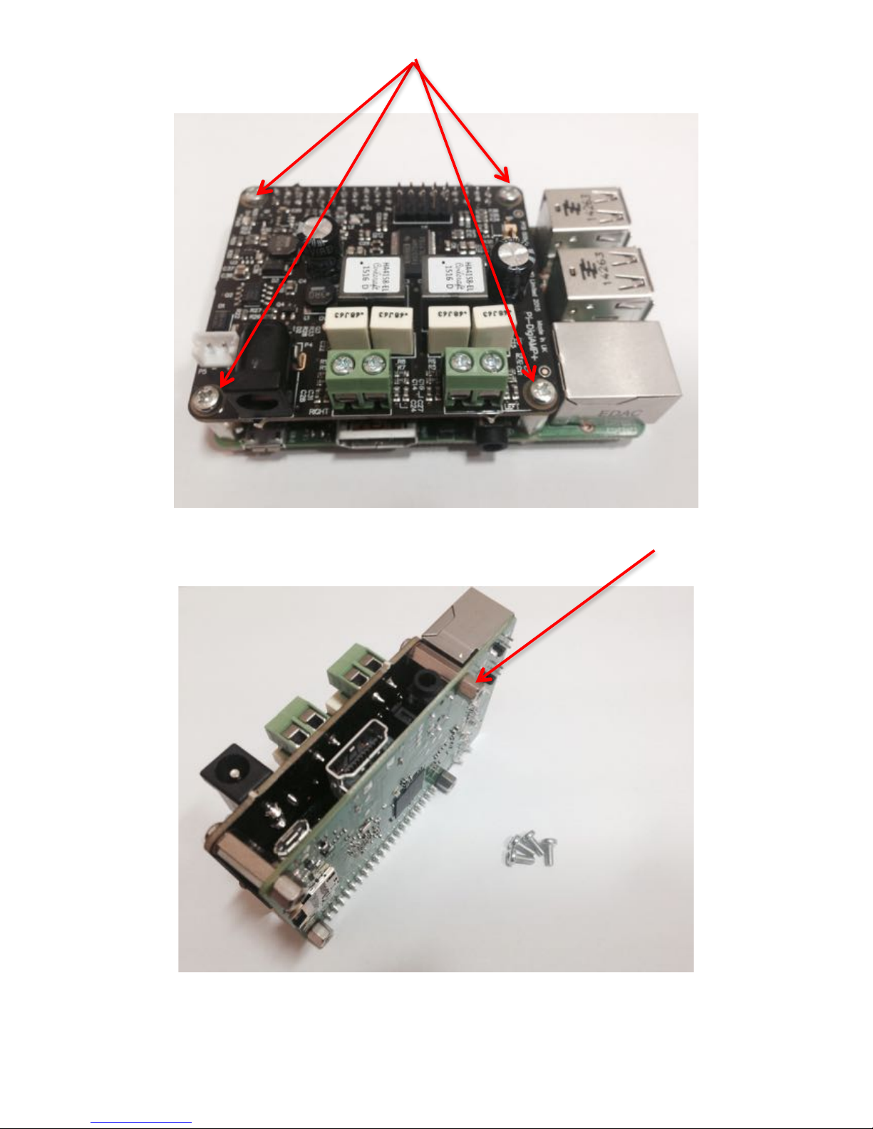
Once the Pi-DAC+ has been fitted the remaining screws can be tightened (finger tight please) as
required.
!
!
If you are using the Pi-CASE+ then replace the 4x screws beneath the Pi with the 4x 5mm PCB
standoffs provided with the Pi-CASE+
! !
v20' ' ''''' 19-Aug-2016'8
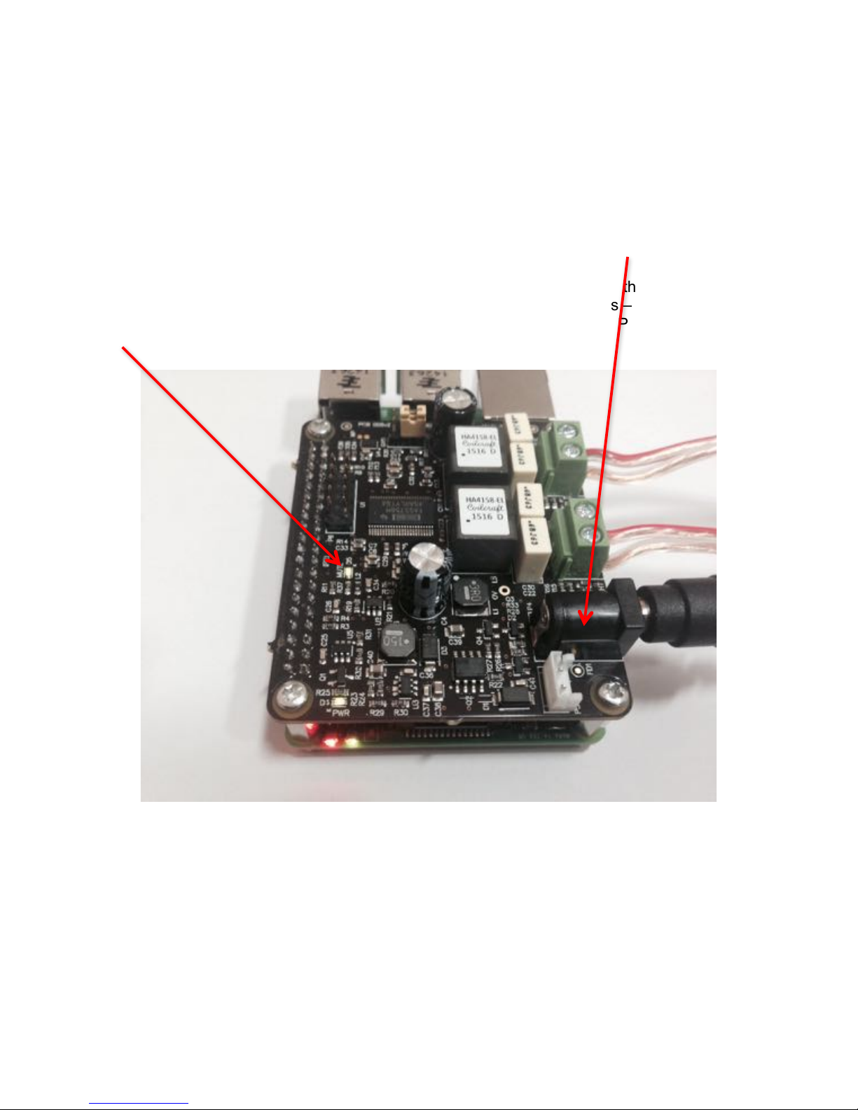
Apply power to your Raspberry Pi in the normal way. You should see that the Raspberry Pi and the
Pi-DAC+ both have power LEDs – this indicates that the power is successfully being applied to the
Pi-DAC+.
!
You can now remove power and reconnect any necessary peripherals.
v20' ' ''''' 19-Aug-2016'9
6)
Connecting the Pi-DigiAMP+ to your Raspberry Pi
WARNING: PLEASE ENSURE ALL CABLES ARE DISCONNECTED FROM THE Pi-DigiAMP+ AND
THE RASPBERRY PI BEFORE ATTEMPTING THIS PROCEDURE.
The Pi-DigiAMP+ can be connected to the Raspberry Pi’s 40way pin header without any additional
soldering.
The Pi-DigiAMP+ is supplied* along with 4x 12mm PCB spacers and 8x M2.5 screws.
The spacers should be screwed (finger tight only) to the Raspberry Pi before adding the Pi-DigiAMP
+.
v20' ' ''''' 19-Aug-2016'10
Once the Pi-DigiAMP+ has been fitted the remaining screws can be tightened (finger tight please) as
require
If you are using the Pi-CASE+ then replace the 4x screws beneath the Pi with the 4x 5mm PCB
standoffs provided with the Pi-CASE+
v20' ' ''''' 19-Aug-2016'11
DO NOT APPLY POWER TO YOUR RASPBERRY PI VIA THE PI’s MICRO USB SOCKET.
The Pi/Pi-DigiAMP+ combination MUST be powered via the Pi-DigiAMP+, not the Raspberry Pi.
Once you are happy with that the Raspberry Pi and Pi-DigiAMP+ are connected correctly you are
nearly ready to apply power.
Power should only be applied to the Pi-DigiAMP+ once speakers have been attached. Powering the
Pi-DigiAMP+ without speakers attached may damage the device.
The Pi-DigiAMP+ has been designed to be powered by the recommended XP Power DC supply. The
Power supply’s output connector should be inserted into the Pi-AMP+’s DC input terminal (marked
P4). Only then should the Power supply’s AC input be plugged into the mains.
When power has been applied to the Pi-DigiAMP+ it will also provide power to the Raspberry Pi. You
should see that the Raspberry Pi and the Pi-DigiAMP+ both have power LEDs – when both are lit it
indicates that the power is successfully being applied to the Pi-DigiAMP+ and Pi. The Pi-DigiAMP+’s
Mute LED will also be lit.
You can now remove power and reconnect any necessary peripherals, install in case etc.
For accurate performance, your loudspeakers must be connected in phase. For both left and right
loudspeakers.
v20' ' ''''' 19-Aug-2016'12
 Loading...