

IQAir Perfect 16 ID-2225, Perfect 16 ID-2530, ID-2530 Perfect 16 Installation Manual
Perfect 16
Installation Manual
IQAir® Perfect 16™ID-Series
MERV16 Micro-Particle Filtration System
Product Data
High-Performance Medical-Grade Residential/Commercial
Air Filtration System
Application
The Perfect 16 ID Series is a V-bank filter system that connects to the return air duct or supply air duct of a forced air system.
This Residential / Commercial Air Filtration System has been designed to provide the highest possible air cleaning rate at the
lowest possible pressure drop for residential and commercial forced air systems. Two models are available.The ID-2225 is ideal
for airflow rates up to 1200 cfm (2040 m3/h) and the ID-2530 for airflow rates up to 2000 cfm (3400 m3/h).
Features
• Ultra efficient: MERV16 certified (ASHRAE 52.2)
• Low air resistance: 0.22 “ w.c. ( 54 Pa) at rated airflow
• Long filter life: 3 years in average home use
• Quick and easy filter replacement: No tools needed
• Easy installation: Requires no electrical connections
• Rugged steel cabinet: Supports weight of furnace
• Medical grade finish: Powder coated galvanized steel
• Fully insulated for installation in unconditioned environments
• Swiss made quality: 10 year warranty
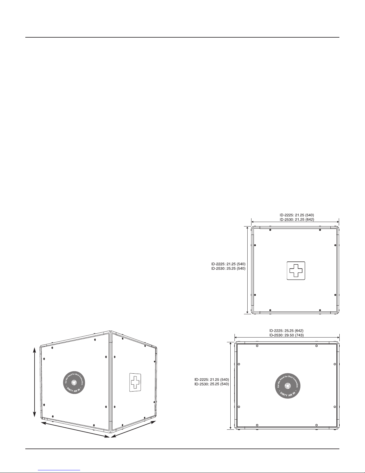
ID-2225: Provide 24 1/2 (622) service clearance in front of unit.
ID-2530: Provide 28 1/2 (721) service clearance in front of unit.
System All measurements in inch (mm)
H
L
W
Page 2
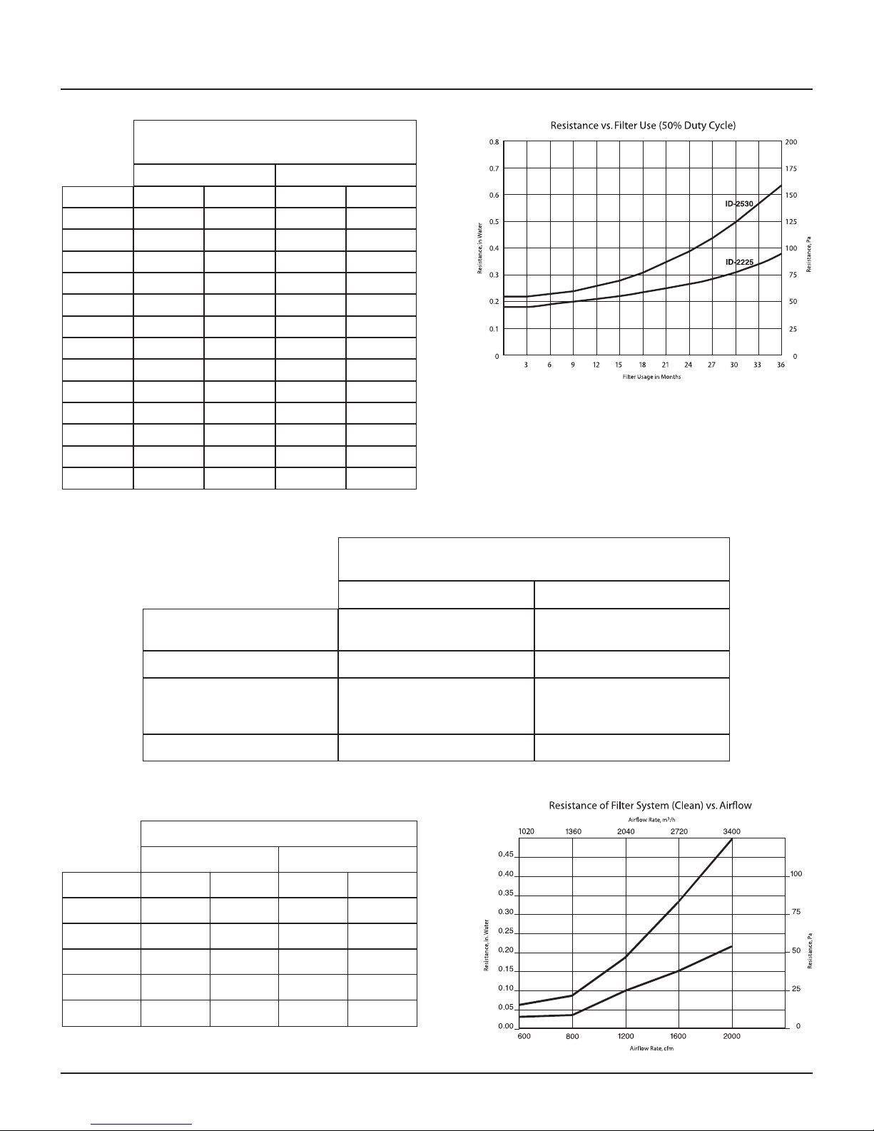
Usage vs. Resistance
ID-2225
ID-2530
verage home based on 50% duty cycle
A
D-2225 at 1200 cfm
I
ilterUsage
F
new 0.18 44 0.22 54
3 months 0.18 45 0.22 55
6 months 0.19 47 0.23 57
9 months 0.20 50 0.24 60
12 months 0.21 53 0.26 64
15 months 0.22 56 0.28 70
18 months 0.24 59 0.31 78
21 months 0.25 62 0.35 87
24 months 0.26 66 0.39 97
27 months 0.28 71 0.44 110
30 months 0.31 77 0.50 125
33 months 0.34 85 0.57 142
36 months 0.38 94 0.64 161
in H2O Pa in H2O Pa
D-2530 at 2000 cfm
I
Performance Data
cfm (m3/h)
600 (1020)
800 (1360)
1200 (2040)
Minimum Efficiency Reporting Data
Minimum Efficiency Reporting
Value (MERV)
Rated airflow
Composite Average Efficiency
Media area
MERV 16@492 fpm (2.5m/s) MERV 16@492 fpm (2.5 m/s)
1400 cfm (2380 m3/h) 2000 cfm (3400 m3/h)
E1 (0.3 – 1.0 µm) = 96.7%
E2 (1.0 – 3.0 µm) = 97.7%
E3 (3.0 – 10.0 µm) = 98.5%
170 sq.ft. (15.8 m2/h) 210 sq.ft. (19.5 m2/h)
Airflow vs. Filter System Resistance
ID-2225 ID-2530
in H2O Pa in H2O Pa
0.06 14 0.03 8
0.09 21 0.04 12
0.18 44 0.10 24
ID-2225 ID-2530
E1 (0.3 – 1.0 µm) = 95.9%
E2 (1.0 – 3.0 µm) = 97.3%
E3 (3.0 – 10.0 µm) = 98.3%
1600 (2720)
2000 (3400) 0.49 122 0.22 54
Based on ASHRAE 52.2 Air Cleaner Performance Reports from Intertek Testing
Services (ETL SEMKO),Cortland, NY
0.33 82 0.15 38
Page 3
Residential Installation
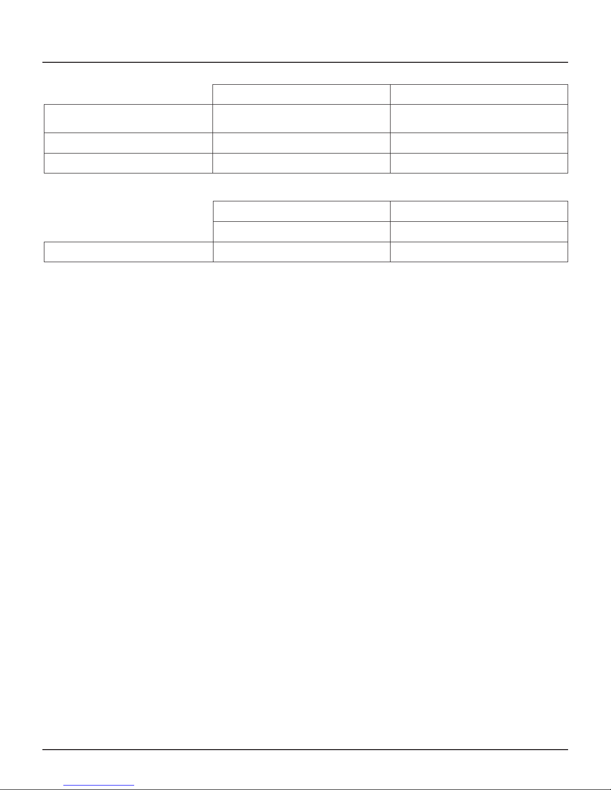
ID-2225 System ID-2530 System
Dimension L x W x H
Weight 59 lbs. (27 kg) 74 lbs. (33.5 kg)
rder No.
O
inch
mm
25.25 x 21.25 x 21.25
642 x 540 x 540
07 80 21 02
2
29.25 x 25.25 x 21.25
743 x 642 x 540
07 80 21 04
2
ID-2225 Replacement Filter Set ID-2530 Replacement Filter Set
SIZE 3 SIZE 4
Order No. 202 11 30 02 (Filter Set, 4 count) 202 11 30 03 (Filter Set, 4 count)
Residential Installation
The Perfect 16 ID-Series can be suspended from exposed ceiling joists or the ceiling surface. Alternatively, it can be floormounted (see page 5 for installation options).
1. Choose a location between the main return duct and the furnace, which is readily accessible for checking and replacing
the filter. Allow at least 24.5 in. (622 mm) clearance in front of the ID-2225 and 28.5 in. (724 mm) clearance in front of the
ID-2530.
2. Adapt connection panel for duct air handler connection as necessary (see page 4). Best performance is achieved with
the 16” x 20” opening for the ID-2225 model, and the 20” x 25” opening for the ID-2530. If flex duct is used, it is strongly
recommended to use 18” round dove tail collar for the ID-2225 and 20” for the ID-2530 for best performance.
3. Determine the correct air inlet and air outlet side of the system. The air inlet is marked with “Cut this Panel for Duct
Connection - DIRTY AIR IN”. The air outlet is marked with “Cut this Panel for Duct Connection - CLEAN AIR OUT”.
Both panels will need to be cut for the proper fit of the ducting prior to installation.
4. If the Perfect 16 system is to be located immediately alongside the furnace, remove filters and secure cabinet via panel
from inside to the furnace with sheet metal screws. Ensure correct airflow direction when reinserting filters.
5. In basement installations, sheet metal turning vanes may be necessary to improve air movement through an elbow in
the duct.
6. Use foil tape to seal all duct joints. Note: All leaks on the return side of the system will cause dirty air to leak into the
return air stream. Leakage also occurs in many furnaces via the blower door. The blower door should also be sealed
with foil tape for the best air cleaning results.
7. Fill out the filter replacement label with the date of the next scheduled filter replacement, which should be no later than 3
years from the current date (based on 50% usage).
8. Check and inspect system for leakage.
9. Test for efficiency with a ParticleScan.
Page 4
 Loading...