

IQAir CleanZone 3020 series, CleanZone 3030 series Installation Manual & Owner's Manual

Installation Guide & Owner’s Manual
CleanZone® 3020 & 3030 Series
for HVAC Integration
Swiss Made
HB_CZ_0407_208 04 01 00

Important Safety
Instructions
IQAir welcomes any suggestions
you may have concerning this
manual and/or the product, or
ways to better serve you. Please
contact us at:
• TO REDUCE THE RISK OF FIRE, ELECTRIC SHOCK, OR INJURY TO PERSON(S) OBSERVE
THE FOLLOWING:
• This manual covers use in residential installations only. Contact IQAir for information on commercial and other uses.
• Installations must be done in accordance with all applicable codes and standards,
including fire-rated construction codes and standards.
• The unit is not designed to provide combustion and/or dilution air for fuel-burning
appliances.
• Do not install in a cooking area or connect directly to an appliance.
IQAir North America, Inc.
CleanZone Assistance
10440 Ontiveros Place
Santa Fe Springs, CA 90670
Email: feedback@iqair.com
WARNING:
The installation of the CleanZone
air cleaning system needs to be
performed by a qualified HVAC
contractor.
WARNING:
This installation guide is designed
to assist in the installation. Since
no installation is alike,the installer
needs to take into account all
factors pertaining to the installation.
• Always disconnect the power cord from electrical outlet before replacing filters,
adding or removing parts and before cleaning.
• When cutting or drilling into wall or ceiling, do not damage electrical wiring or
other hidden utilities.
• This unit must be grounded.The power supply cord has a 3-prong grounding plug
for your personal safety. It must be plugged into a mating 3-prong grounding
receptacle,grounded in accordancewith the national electricalcode and localcodes
and ordinances.Do not remove the ground prong. Do not use an extension cord.
• This unit must be installed in a weatherized location out of direct sunlight and
protected by the elements.
• When the ambient temperature for the unit location is below freezing
(32°F – 0°C), the unit must run continuously to prevent condensation.
• Do not attempt to recover in any way the exhaust air from a dryer or a range hood.
This would cause clogging of the filters and constitute a fire hazard. This will also
void the warranty.
• Do not operate this appliance if it has a damaged cord or plug,if the motor fan fails
to rotate, if it is not working properly, if it has been dropped or damaged. Contact
IQAir for repair or replacement part service.
• Use this unit only in the manner intended by the manufacturer. If you have
questions, contact the manufacturer at the address or telephone number listed in
this document.
• Do not use this appliance in areas with very high concentrations of dusts or
powder to prevent the danger of dust explosions.
• Do not use this appliance in explosive areas.
• Only use original IQAir® filters and accessories.
• Do not run any air ducts directly above or closer than 2 ft (0.6 m) to any furnace or
its supply plenum, boiler or other heat producing appliance.
• The ductwork must be be installed in compliance with all local and national codes
that are applicable.
• Keep the power cord away from heated surfaces.
• If the unit is used during construction or renovation, regularly check filters for
prematurely clogged filters.
• Save these instructions for future reference.
2

Table of Contents
Important Safety Instructions 2
Modular Housing Concept 4
Tool & Materials Checklist 4
Planning Your Installation 5
Chapter 1 Installation Diagrams 6
Model 3030 6
Model 3020 7
Chapter 2 System Components 8
Model 3030 8
Model 3020 10
How the System Works 12
Chapter 3 CleanZone Assembly 14
Unpacking the Modules 14
Preparing the HyperHEPA Module 15
Connecting the HyperHEPA and Motor Module 16
Placing the HyperHEPA Filter 17
Finishing the Module Assembly 17
Attachment of the Air Inlet and Outlet Panels 18
Chapter 4 Electrical Connections 19
Power Cord 19
EAC TerminalWire 19
Control Panel 19
Chapter 5 Mounting of the Control Panel 20
Mounting for Wall Surface Wiring 20
Mounting for Through Wall Wiring 21
Chapter 6 Control Panel Functions 22
Description of the Control Panel Elements 22
Menu Items 23
Filter Life Monitor 24
New Filter Reset 25
Initial Installer Set-Up of the Control Panel 26
Setting the System Airflow 27
Filter Configuration 28
Password Menu 30
Chapter 7 Replacing Filters 31
Replacing the Micro-Particle Filters 32
Replacing the HyperHEPA Filter 33
New Filter Reset 34
3

Modular Housing
Concept
The IQAir CleanZone air cleaning system is based on a modular architecture that allows
for easy system customization and regular non-palletized shipment.
Each CleanZone system is made up of a motor module and at least one filter module.
Each of these modules is supplied in a separate transport box.
Tool & Materials
Checklist
To assemble the CleanZone system components the following tools are necessary:
Hand tools:
Torx-30 Screwdriver
4mm Hex Ballpoint Screwdriver (supplied in CleanZone Basic Tool Kit)
Crimping tool for quick connect terminals
PowerTools (optional):
Cordless Driver-Drill
Torx-30 Ballpoint Power Bit (supplied in CleanZone Basic Tool Kit)
Torx-30 Power Bit (supplied in CleanZone Basic Tool Kit)
Materials Checklist
The CleanZone components are shipped with all necessary materials to be assembled.The
following list is designed as guide to the other materials that may be required for the installation:
Ducting
• Flex duct (18” recommended) or other ducting from return grille to CleanZone
• Return plenums
• T-wyes and elbows
• Return platform
• Miscellaneous items: cable ties,sheet metal screws, duct mastic,approved duct
tape, plumbers tape
• Insulation for T-wyes, elbows and return plenums when installed in unconditioned spaces
Electrical
• Two
• Rigid wire to fish control panel wire through wall Mounting
• Chains, straps, threaded bars
1
⁄4-in female quick connect terminals (for 16–14 wire) for the EAC IN wire
connection to the air handling control board.
4

Planning your
Installation
When planning the installation of
the CleanZone® system, keep the
following considerations in mind:
Installation Principle
Single speed 2-3 ton HVAC systems
The CleanZone system is designed to go inline to the residential HVAC return duct in
installations up to airflow rates of 1200 cfm. If the airflow is lower than 1000 cfm, the
CleanZone fan speed should be reduced also. The CleanZone is designed to replace all
existing furnace filters or similar.
Single speed 4-5 ton HVAC systems
In installations, with airflow rates of over 1200 cfm, a filtered bypass (additional Perfect 16)
needs to be installed to make up for the additional HVAC system airflow.The CleanZone is
designed to replace all existing furnace filters or similar.
Multiple speed 2-3 ton HVAC systems
In installations with 2-3 ton multiple speed air handling systems,the CleanZone is designed
to go inline to the residential HVAC return duct. Integration of a excess air bypass duct into
the duct design is necessary to allow excess air to be circulated back to the air cleaning
system on speed setting of less than 1000 cfm. If the maximum airflow of the HVAC
system is lower than 1000 cfm, the CleanZone fan speed should be reduced also.
Multiple speed 4-5 ton HVAC systems
In installations, with airflow rates of over 1200 cfm, a filtered bypass needs to be installed
to make up for the system airflow and the maximum of 1200 cfm supplied by the
CleanZone air cleaning system. This filtered bypass will also serve as a excess air bypass
duct, as it allows recirculation of excess air when HVAC airflow capacity is reduced to
less than 1000 cfm.
LOCATION
• The CleanZone should be located on the return side (upstream) of the air handling
system. Please note that locating the CleanZone on the supply side (down stream)
may cause the motor and/or electronics in the CleanZone to fail due to overheating
or condensation.
• For best performance, the CleanZone should be connected as close to the air
handling system as possible. Duct runs to and from the CleanZone should be held
as short as possible.
• Choose a location that is readily accessible for checking and replacing the filter(s).Allow
at least 24
• Note that the micro-particle V-bank filters can only be replaced through the square
panels.The HyperHEPA filter can be replaced from all four sides of the unit.
MOUNTING
• If positioned on the floor or a platform, anti-vibration pads (supplied with the unit)
should be used to reduce vibration.
• If the unit is suspended,screws must not penetrate through the cabinet. Make sure that
you have the proper equipment to keep the unit secure.
DUCTING
• Installed duct runs should be as straight as possible.
• If flex duct is used, the preferred duct diameter is 18”.
• For best indoor air quality, fiberglass ductboard or fiberglass lined ducts are not
recommended.
• To reduce the possibility of noise from the CleanZone system travelling down to the
return grille, a minimum return duct length of 6 feet is recommended.
ELECTRICITY
• The CleanZone requires a 120 Vac grounded electrical outlet.If an outlet is not available,
have a qualified electrician install one.
1
⁄2in. (622 mm) clearance in front of the unit.
5
Chapter 1
Supply Duct
Furnace
Fresh Air
(Optional)
Return Plenum
Return Air
Return Air
CleanZone
®
MERV16
Micro-Particle
Filter Module
Return Plenum
CleanZone
®
HyperHEPA
®
Nano-Particle
Filter Module
CleanZone
®
Motor Module
Perfect16
®
ID-Series
Micro-Particle
Filter Module
Supply Duct
Furnace
Fresh Air
(Optional)
Return Plenum
Multiple
Speed
Bypass
Return Air
CleanZone
®
MERV16
Micro-Particle
Filter Module
CleanZone
®
HyperHEPA
®
Nano-Particle
Filter Module
CleanZone
®
Motor Module
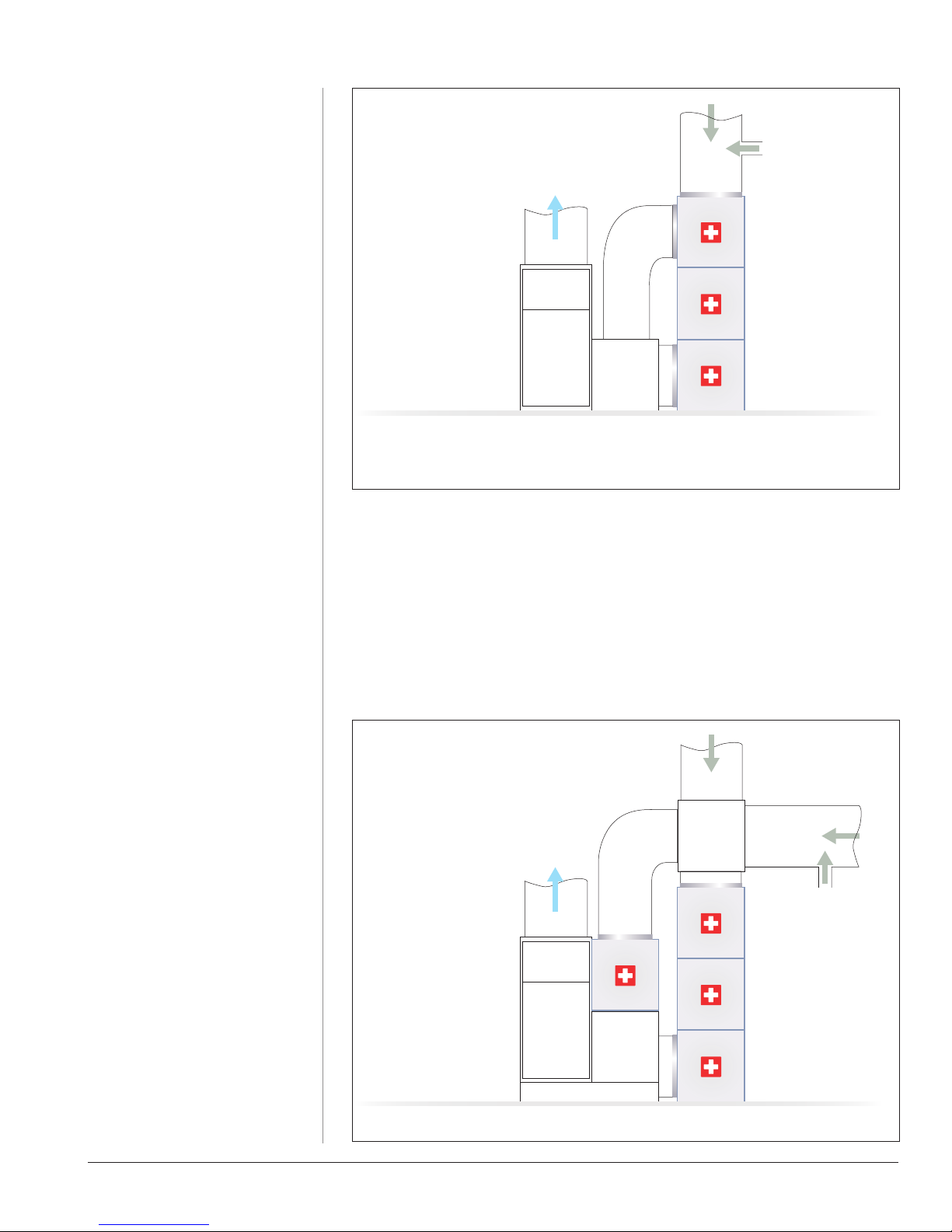
Installation Diagrams
MODEL 3030
Preferred Basement Installation
*
2–3 ton installation (side view).
* Multiple Speed Bypass is required for multiple speed HVAC systems.
For 2–3 ton basement
installations the following CleanZone
items are recommended:
1 CleanZone 3030
(incl. 2 connection panels)
1 additional connection panel if
multiple speed bypass connection
For 4–5 ton basement
installations the following combination
is recommended:
1 CleanZone 3030
(incl. 2 connection panels)
1 Perfect 16 ID-2225
(incl. 2 connection panels)
4–5 ton installation with multiple returns (side view)
6Chapter 1
Perfect16
®
ID-Series
Micro-Particle
Filter Module
Supply Duct Furnace
Fresh Air
(Optional)
Return Plenum
Return Air
CleanZone
®
HyperHEPA
®
Nano-Particle
Filter Module
CleanZone
®
Motor Module
Multiple
Speed
Bypass
Perfect16
®
ID-Series
Micro-Particle
Filter Module
Supply Duct
Furnace
Fresh Air
(Optional)
Return Plenum
Return Air
Perfect16
®
ID-Series
Micro-Particle
Filter Module
Return Plenum
Return Plenum
CleanZone
®
HyperHEPA
®
Nano-Particle
Filter Module
CleanZone
®
Motor Module
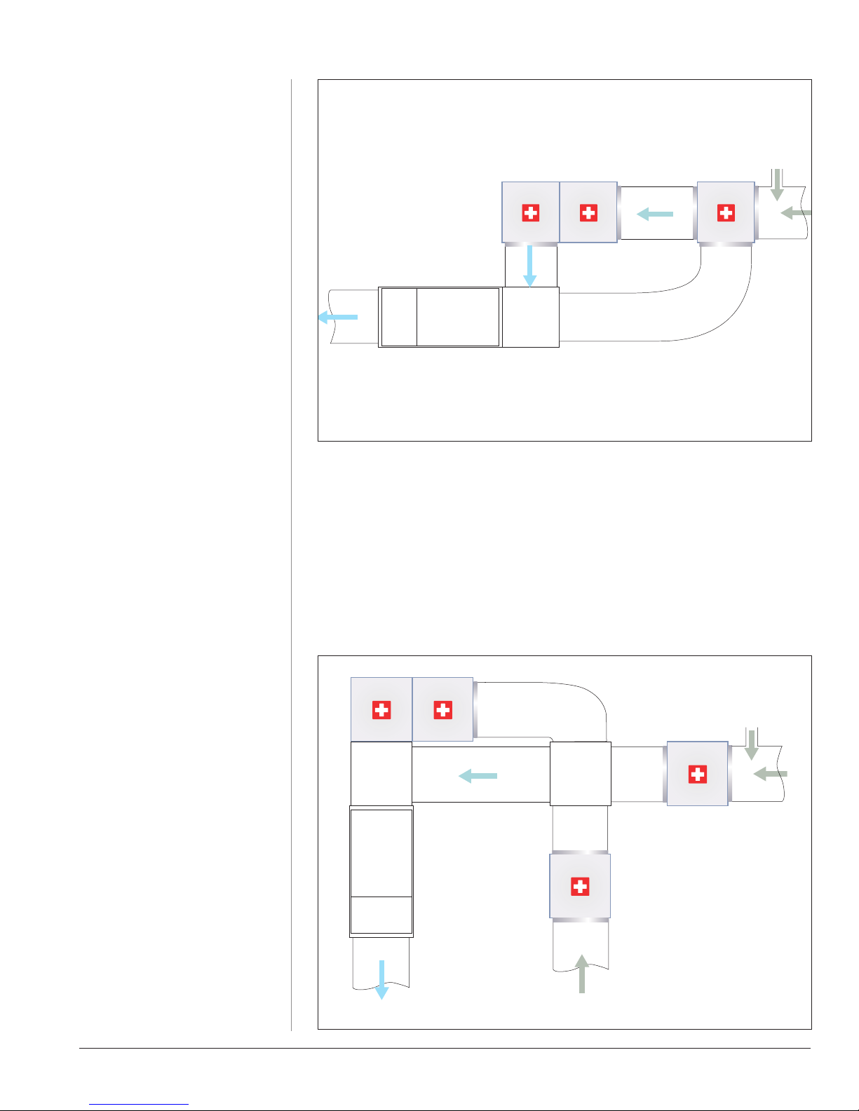
Installation Diagrams
MODEL 3020
Preferred Attic Installation
2–3 ton installation (bird’s eye view).
* Multiple Speed Bypass is required for multiple speed HVAC systems.
For 2–3 ton basement
installations the following combination is
recommended:
1 CleanZone 3020
(incl. 2 connection panels)
1 Perfect 16 ID-2225
(incl. 2 connection panels)
1 additional connection panel if
multiple speed bypass connection
For 4–5 ton basement
installations the following combination
is recommended:
1 CleanZone 3020
(incl. 2 connection panels)
2 Perfect 16 ID-2225
(incl. 2 connection panels each)
4–5 ton single or multiple speed installation (bird’s eye view)
7Chapter 1
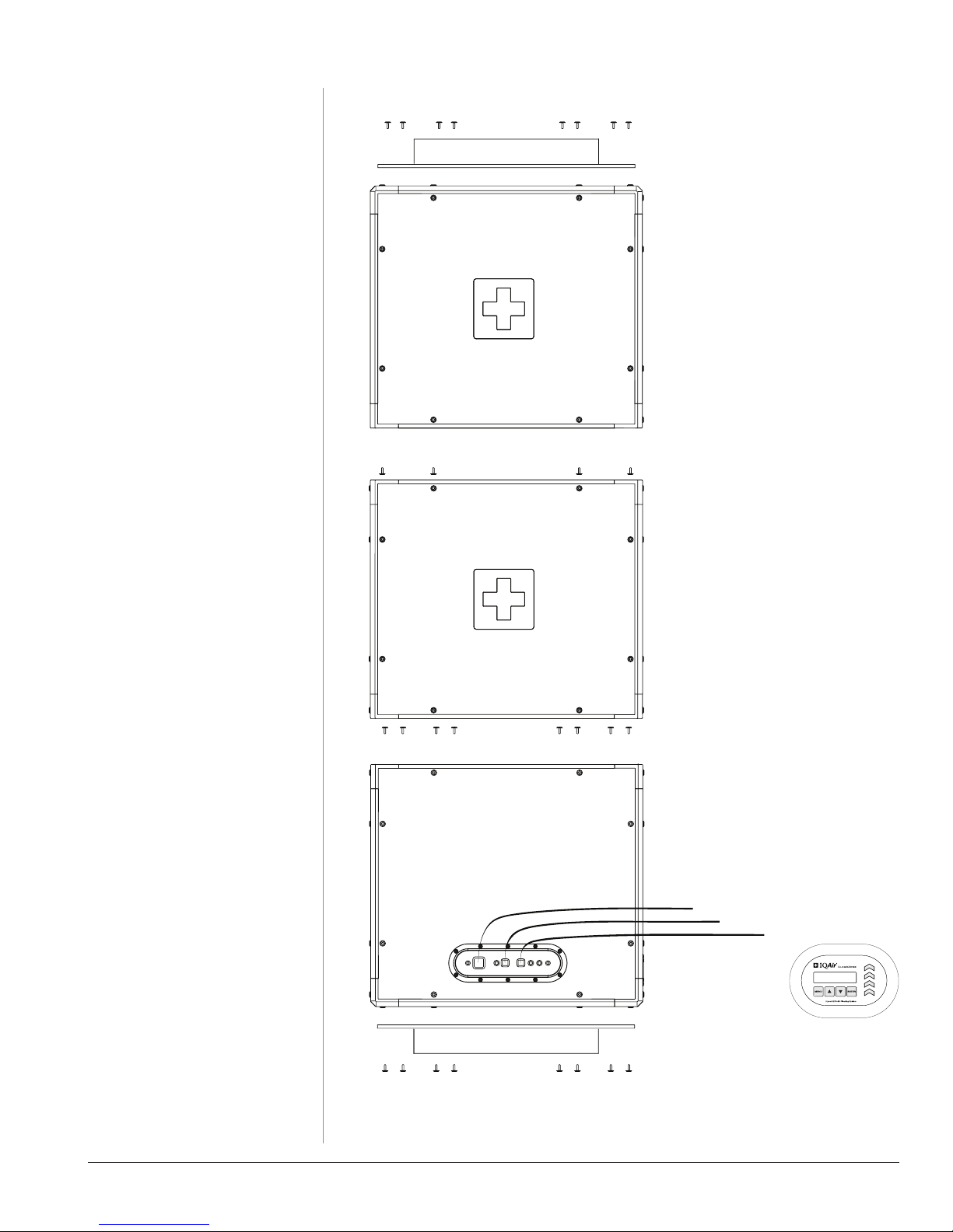
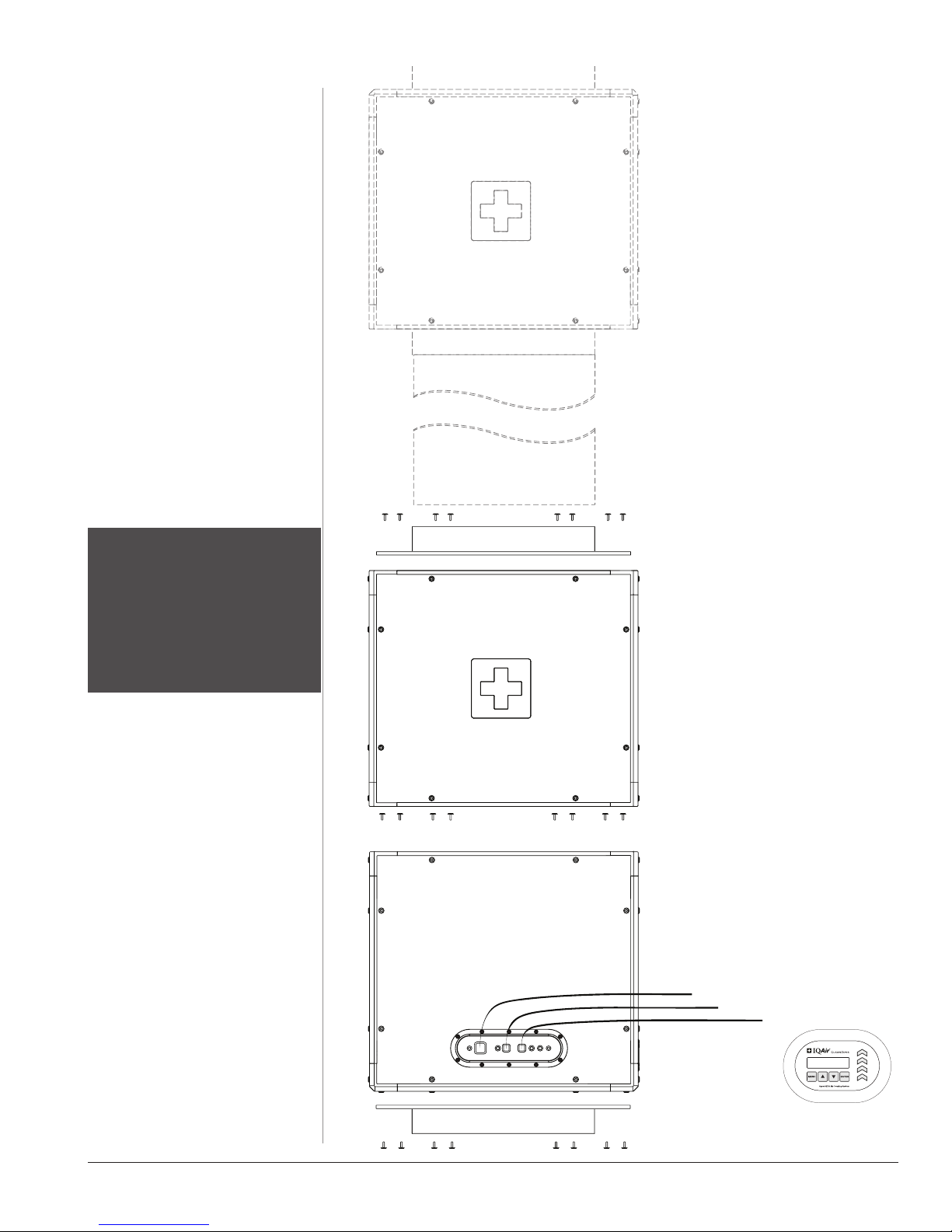
Chapter 2
System Components
MODEL 3030
Eight Torx-30 screws
Rectangular Connection Panel
Micro-Particle Filter
End Module (MERV 16)
Four 4 mm Hex screws
HyperHEPA Middle Module
(Nano-Particle Filtration)
Eight 4 mm Hex screws
Motor End Module
Power cord with 3-prong 120 Vac
connector plug with ground
EAC terminal connection cord
Rectangular Connection Panel
Wall control panel cord
Eight Torx-30 screws
8Chapter 2
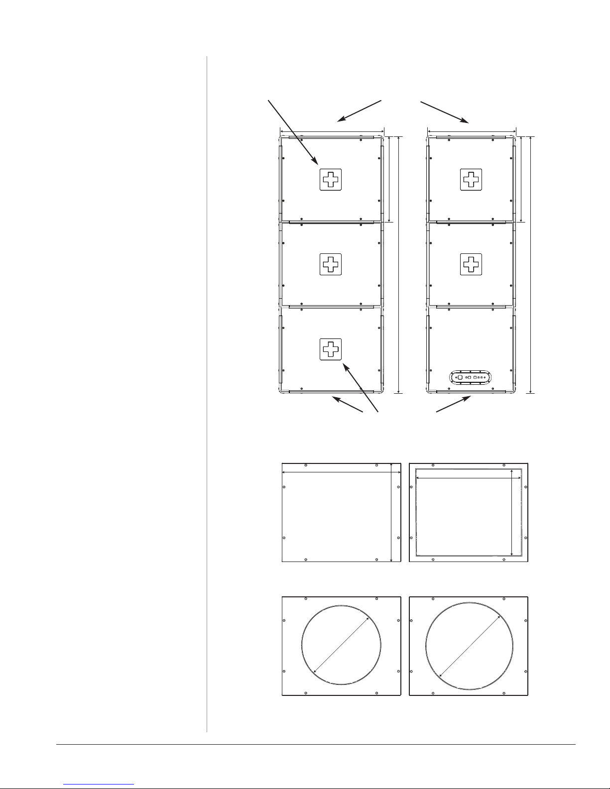
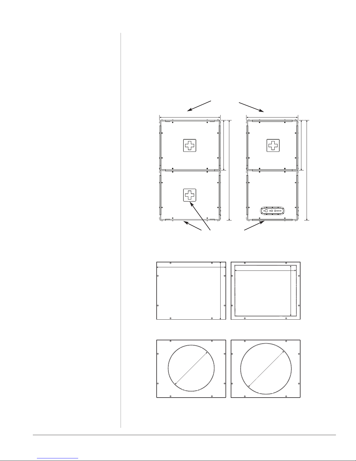
16 (400)
18 (450)
20 (500)
16 (400)
23.69 (601)
19.63 (499)
can be cut and adapted
61.75 (1568)
25.25 (642)
20.75 (527)
61.75 (1568)
21.25 (540)
20.75 (527)
Dimensions
Connection panel for optional
multiple speed bypass
Connection panel for air inlet
attaches to face of system
Connection Panels
Four different connection panels are
available:
• Panel without opening
(to be cut and adapted as neces-
sary by installer)
Order No. 207 30 05 04
• Panel with16” x 20” connection
Order No. 207 30 09 04
• Panel with 16”round connection
Order No. 207 30 06 04
• Panel with 18”round connection
Order No. 207 30 07 04
Connection panel for air outlet attaches
to face or long side of system
All measurements in inch (mm)
9Chapter 2
SystemComponents
MODEL 3020
TheCleanZone 3020wasdesigned to
allow more installation flexibility in
tight spaces.For the CleanZone 3020
to function properly it requires a
Perfect 16 filter for pre-filtration.The
Perfect 16 can be connected to the
CleanZone withas muchas 20 feetof
duct distance between the two.
If flex duct is used, 18” diameter is
recommended.
Perfect 16
Micro-Particle Filter
(to be ordered separately)
Eight Torx-30 screws
ATTENTION
Failure to use a Perfect 16 for prefiltration of a CleanZone 3020 will
cause the HyperHEPA filter to
become pre-maturely loaded and
can lead to a drastic reduction of
airflow.
Rectangular Connection Panel
HyperHEPA End Module
(Nano-Particle Filtration)
Eight 4 mm Hex screws
Motor End Module
Power cord with 3-prong 120 Vac
connector plug with ground
EAC terminal connection cord
Wall control panel cord
Rectangular Connection Panel
Eight Torx-30 screws
10Chapter 2
16 (400)
18 (450)
20 (500)
16 (400)
23.69 (601)
19.63 (499)
can be cut and adapted
41.5 (1055)
25.25 (642)
20.75 (527)
41.5 (1055)
25.25 (642)
20.75 (527)
Dimensions
Connection panel for air inlet
attaches to face of system
Connection Panels
Four different connection panels are
available:
• Panel without opening
(to be cut and adapted as neces-
sary by installer)
Order No. 207 30 05 04
• Panel with16” x 20” connection
Order No. 207 30 09 04
• Panel with 16”round connection
Order No. 207 30 06 04
• Panel with 18”round connection
Order No. 207 30 07 04
Connection panel for air outlet attaches
to face or long side of system
All measurements in inch (mm)
11Chapter 2
 Loading...