

IPS TS33-ON Series, TS33-ON-30k0, TS33-ON-10k0, TS33-ON-15k0, TS33-ON-20k0 Installation Manual
Page 1
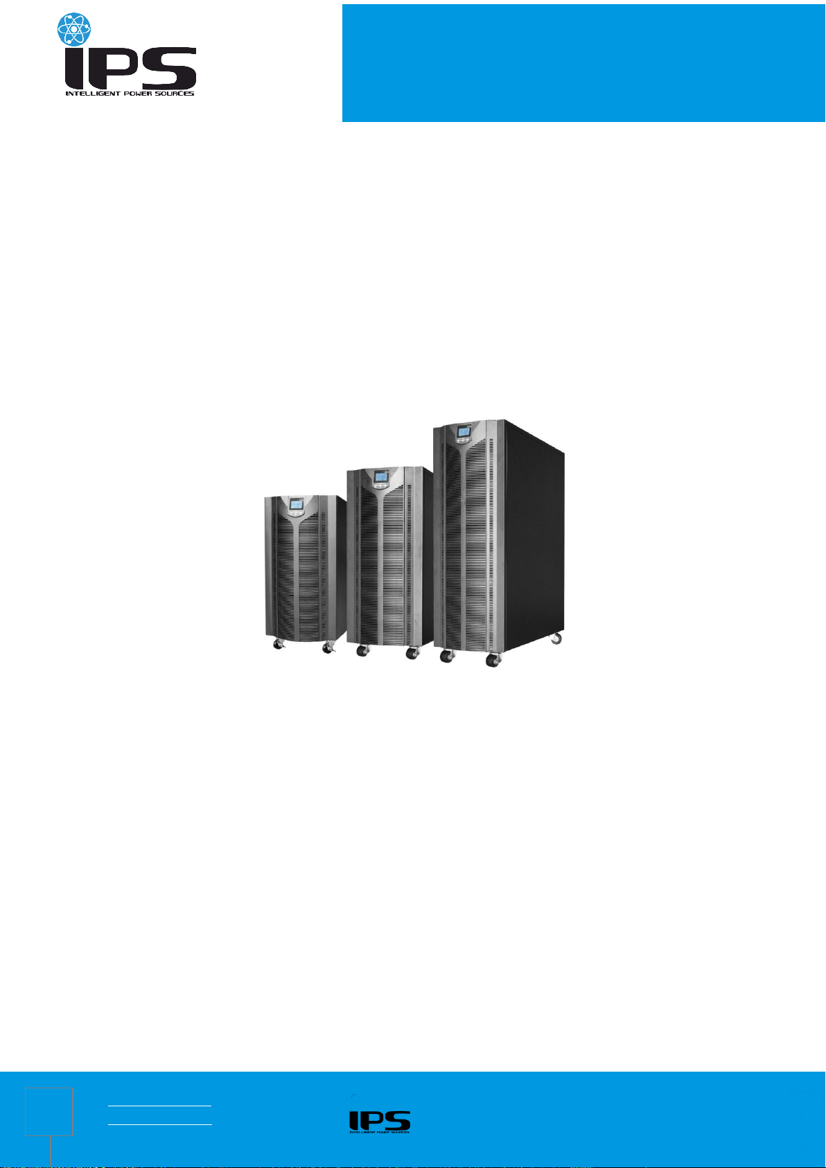
SERIES TS33-ON
1
Instalation manual for three-three phase
true-online UPS
For models:
TS33-ON-10k0
TS33-ON-15k0
TS33-ON-20k0
TS33-ON-30k0
www.ips-ups.eu 28.05.2018
info@ips-ups.eu TS33-ON-manual_EN-R0
Page 2

2
1 Safety Information 3
2 Product Overview 4
2.1 Specifications 4
2.2 Front panel features 5
3 Installation 8
3.1 Unpacking inspection 8
3.2 Single System Installation 8
3.3 Parallel System installation 10
4 Operation Instructions 13
4.1 Display panel 13
4.2 UPS settings 16
SERIES TS33-ON
Table of Contents
4.3 Parameters inquiry 26
4.4 Event log query 27
4.5 UPS On / Off operation 28
4.6 Connect the communication 29
4.7 Parallel UPS operation 31
5 Operation Modes 32
5.1 Power-up mode / Shutdown mode 32
5.2 Standby mode 32
5.3 Bypass mode 33
5.4 Mains power mode (Frequency conversion mode) 33
5.5 Battery mode / battery self test mode 34
5.6 ECO mode 34
5.7 Fault mode 35
5.8 Maintenance bypass 36
5.9 Test mode 36
6 Troubleshooting 37
www.ips-ups.eu 28.05.2018
info@ips-ups.eu TS33-ON-manual_EN-R0
Page 3
3
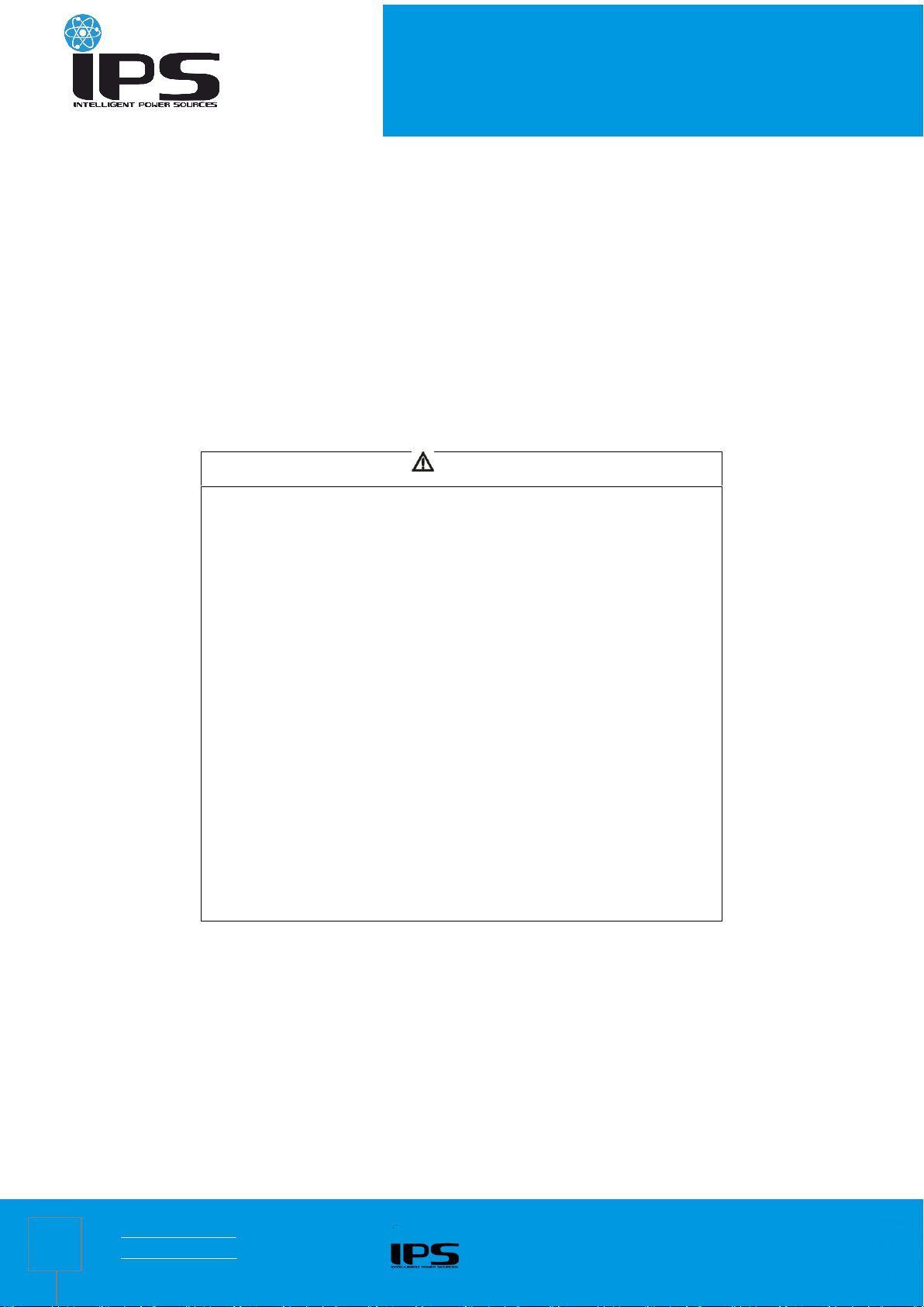
CAUTION
Non-qualified electricians are forbidden to open the case due to hazard
of electrical shock.
Consulting the dealer is required before using for below equipment. Its
application, configuration, management and maintenance must be
specially considered and designed.
Medical equipment which is directly related to patients’life
Elevator and other equipment which may endanger personal
safety
WARNING
The UPS must be properly earthed / grounded and due to a high leakage
current, the earthing / grounding conductor must be connected first.
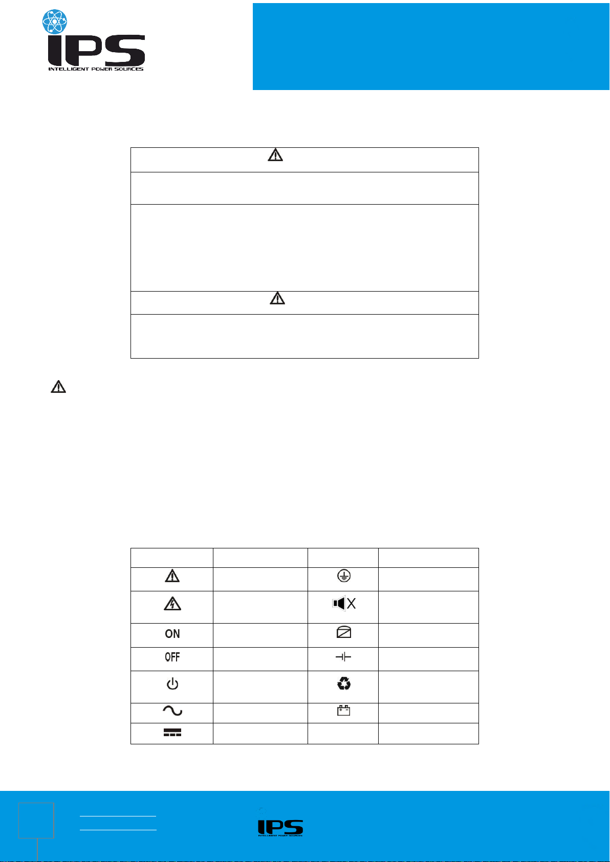
Symbol
Significations
Symbol
Significations
Caution
Protective earth
Danger! High
Voltage!
Disable/mute
audible alarm
Turn on
Bypass
Turn off
Battery inspection
Standby or
Shutdown
Repeat
AC
Battery
DC
1 Safety Information
SERIES TS33-ON
Safety and General Information
Read all safety information and operating instructions carefully before attempting to install, operate, service or maintain the UPS.
The UPS contains internal batteries and may present a shock hazard even when disconnected from the branch circuit (mains).
The protective earth conductor for the UPS carries the leakage current from the load devices (computer equipment). An
insulated ground conductor is to be installed as part of the branch circuit that supplies the UPS. The conductor must have the
same size and insulation material as the grounded and ungrounded branch circuit supply conductors.
Do not use liquid extinguisher if there is a fire, a dry powder extinguisher is recommended.
Disconnect all connection wiring before maintenance or cleaning to avoid the risk of electric shock.
Do not dispose of the batteries with fire. The batteries may explode.
Do not open or mutilate batteries. Released electrolyte inside is harmful to the skin and eyes, and maybe toxic.
Do not connect the positive pole and negative pole directly, otherwise it will cause electric shocks or will be on fire.
It is not suitable to connect some electric equipments such as hair drier and heating appliance.
Note:Symbol instructions
www.ips-ups.eu 28.05.2018
info@ips-ups.eu TS33-ON-manual_EN-R0
Page 4
4
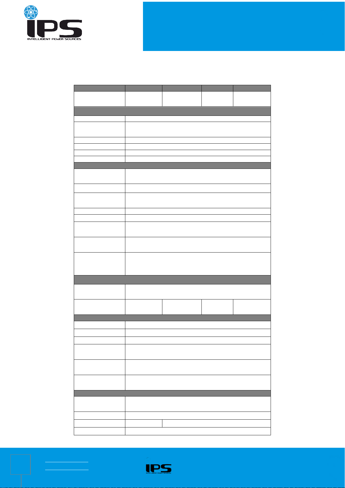
2 Product Overview
MODEL
10 kVA
15 kVA
20 kVA
30 kVA
Capacity
10 kVA
/ 9 kW
15 kVA
/ 13.5kW
20 kVA
/ 18 kW
30 kVA
/ 27 kW
INPUT
Nominal voltage
360V / 380V / 400V / 415 Vac three-phase (3Φ+N+PE)
Voltage range
277 ~ 485 Vac (no derating)
190 ~ 277 Vac (linear derating between 50% and 100% load)
Rated frequency
50 / 60 Hz (auto-sense)
Frequency range
40 ~ 70 Hz
Power factor
≥ 0.99
Bypass voltage range
-40% ~ +15% (settable)
OUTPUT
Nominal voltage
360V / 380V / 400V / 415 Vac three-phase (3Φ+N+PE)
(settable)
Voltage regulation
± 1%
Frequency
Synchronized with utility in utility mode;
50 / 60 ± 0.1 Hz in battery mode
Power factor
0.9
Crest factor
3:1
Total harmonic
distortion (THDV)
≤ 2% (linear load); ≤ 5% (non-linear load)
Transfer time
Mains mode to battery mode: 0 ms;
Inverter mode to bypass mode: 0 ms
Inverter overload
capability
102% ~ 125%: transfer to bypass in 10 min;
125% ~ 150%: transfer to bypass in 1 min;
> 150%: transfer to bypass in 0.5 s
BATTERY
DC voltage
Standard model: 240 Vdc; Long time model: 192 Vdc
(192V/216V/240V optional)
Inbuilt battery of
standard model
20*7 AH
40*7 AH
40*9 AH
60*9 AH
SYSTEM
Efficiency
Line mode: ≥ 93%; ECO mode: ≥98
Display
LCD+LED
Alarm
Battery mode, low battery, fans fault etc.
Max. parallel
numbers
6
Protections
Short-circuit – overload – overtemperature –low battery –
overvoltage – undervoltage – fans fault
Communications
RS232 / USB / EPO (standard) ; RS485 / AS400 / SNMP
(optional)
OTHERS
Operating
temperature
0 ~ 40℃
Relative humidity
< 95% (non-condensing)
Noise level
≤ 60 dB (1m)
≤ 65 dB (1m)
IP rating
IP20
2.1 Specifications
SERIES TS33-ON
www.ips-ups.eu 28.05.2018
info@ips-ups.eu TS33-ON-manual_EN-R0
Page 5

SERIES TS33-ON
5
Dimensions ( W*D*H)
(mm)
350×655×732 (H)
350×785×858
(S)
350×785×1078 (S)
Packaged
dimensions ( W*D*H)
(mm)
472×780×920 (H)
472×910×1050
(S)
472×910×1260 (S)
Net weight (kg)
55 (H),110 (S)
60 (H), 155 (S)
61 (H), 175
(S)
65 (H), 235 (S)
Gross weight (kg)
65 (H), 125 (S)
70 (H), 170 (S)
71 (H), 190
(S)
75 (H), 250 (S)
Front panel of 10kVA standard
model UPS (1 floor batteries)
Front panel of standard
model UPS (3 floors batteries)
Front panel of long
time model UPS
H means Long time model w/o inbuilt battery; S means Standard model with inbuilt battery.Derate capacity to 90%
when the output voltage is adjusted to 360Vac.
2.2 Front panel features
www.ips-ups.eu 28.05.2018
info@ips-ups.eu TS33-ON-manual_EN-R0
Page 6

6
Rear panel of 10kVA
Rear panel of 10kVA
standard model UPS
Rear panel of 15k / 20k /
30k long time model UPS
Rear panel of 15k/ 20k/
30k standard model UPS
Rear panel of 10kVA
standard model UPS
2.3 Rear panel features
SERIES TS33-ON
www.ips-ups.eu 28.05.2018
info@ips-ups.eu TS33-ON-manual_EN-R0
Page 7

SERIES TS33-ON
7
① Main input terminal
⑨ RS232 port
② Battery input terminal
⑩ USB port
③ Bypass input terminal
⑪ EPO
④ Output terminal
⑫Battery temperature compensation
sensor (optional)
⑤ Main input breaker
⑬ Intelligent slot 1 (SNMP / AS400 /
RS485 optional)
⑥ Bypass input breaker
⑭Intelligent slot 2 (SNMP / AS400 /
RS485 optional)
⑦ Maintenance switch
⑮ Parallel port (optional)
⑧ Fan
⑯ Inbuilt battery breaker
www.ips-ups.eu 28.05.2018
info@ips-ups.eu TS33-ON-manual_EN-R0
Page 8
SERIES TS33-ON
8
CAUTION
when connect the loads with the UPS, turn off all the loads first, then
connect power cables and turn on the loads one by one.
UPS must be connected to the distribution board with overcurrent protective
breaker.
All power cables should be connected to the protective earthing.
No matter whether connects the input power cables or not, the UPS output
may present electricity. To make the UPS have no output, turning off the
UPS first is required, and then disconnects the mains power supply.
To connect inductive loads such as motor and laser printer ect., due to their
excessive starting power, UPS capacity should be calculated by starting
power which normally is twice as much as its rated power.
If connect to a generator, follow this procedure:
Turn on the generator, wait until it works normally and connect its output to
the UPS input terminal (Verify that UPS has no-load at this moment),then
start up the UPS and connect the loads one by one (it is suggested that
users choose the generator which is 1.2 times bigger than UPS capacity). If
the generator has no enough endurance ability to shock (it shows switching
to battery mode due to utility high voltage), it can be switched to bypass
mode to take loads and then start UPS again to go to utility mode.
For standard model UPS, it is suggested that users charge batteries more
than 8hs before using. Once mains input power is connected, the UPS can
automatically charge the battery. Even not charge, it can be used at once,
but its backup time will be less than standard value.
After finishing installation, verify that the installation is correct.
If install the protective leakage current switch, it should be installed on the
UPS output terminal.
3 Installation
3.1 Unpacking inspection
Open the UPS package and inspect the contents upon receipt. The accessories attached to the UPS contain a
user manual, RS232 & USB communication cable, CD-ROM.
Check if the unit is damaged during transport. Do not power on and notify the carrier and dealer if find
damaged or parts missing.
Verify this unit is the model you want to buy. Check the model name showed both on the front panel and rear
panel.
Note:
Keep the packaging box and packaging materials for reuse. The equipment is heavy. Always handle it with care.
3.2 Single System Installation
3.2.1 Installation environment and location
Install the UPS system in a temperature controlled environment free of conductive contaminants and humidity.
Install the UPS system on a non-flammable, level and solid surface (e.g. concrete) that can support the weight of the
system.
The UPS system can not be placed up against the wall. Keep adequate space for proper ventilation of air inlet in the
bottom of front panel, air outlet of fans on the rear cover plate and air inlet of enclosure sides.
The ambient temperature of the UPS should be 0 °C to 40 °C.
There may be condensing If unpacking in low temperature, the UPS must be waited until inside and outside of the UPS are
completely dry for installation, otherwise there is hazard of electric shock.
Place the UPS close to the mains input power distribution so as to cut off mains input switch and power supply in
emergency situation.
www.ips-ups.eu 28.05.2018
info@ips-ups.eu TS33-ON-manual_EN-R0
Page 9

SERIES TS33-ON
9
Model
Maximum current(A)
Mains / Bypass input
Output
Battery
N wire
10kVA
24
24
60
42
15kVA
35
35
94
61
20kVA
46
46
125
79
30kVA
60
60
180
116
Positive
Battery
+
-
Battery
+
-
Battery
+
-
Battery
+
-
Negative
16/18/20
To Battery input terminal of UPS
battery breaker
3.2.2 Wiring
The UPS system uses terminal block for input and output connections. The requirements for the cable current
are as follows:
Remark: when the main load is a kind of linear load, the N line cable can be selected the same cross
sectional area as the mains live line cable; when the main load is a kind of non-linear load, the Null current is 1.5-
1.7 times as big as the Live current, and it needs to be selected according to the recommended N line cable current
in the above table. If it is multiconductor cable, it should be selected according to the cross sectional area of the N
line cable.
Terminal block
Note:Ensure that the input / output cables must be connected firmly to the input / output terminals, bad contacts
are not allowable. It is suggested that the earth wire is close to the input / output wire size.
3.2.3 Connect external battery (Long time model UPS)
The default configuration of Long time model UPS use 16pcs batteries, standard model UPS use 20pcs as default. If it was
customized to be 14/16/18/20pcs before factory delivery, connect proper batteries according to the customized battery
quantity. If need to change battery configuration, contact your local dealer for modification.
Strictly follow these steps:
Battery switch is OFF, connect batteries in series and ensure proper battery voltage.
Battery cables must be connected to the battery terminal first (Connecting to the UPS terminal first has hazard of
electric shock), red wire is connected to BAT+, black wire to BAT-.
Use proper battery cables to connect the UPS and batteries. The DC breaker between UPS and batteries is required.
Not to connect UPS to any loads first, close the battery breaker and provide mains power to the UPS (close the UPS input
breaker), UPS will charge the battery group.
www.ips-ups.eu 28.05.2018
info@ips-ups.eu TS33-ON-manual_EN-R0
10-30k long time model UPS battery connection
Page 10
SERIES TS33-ON
10
3.3 Parallel System installation
Parallel function is optional. Parallel kits include parallel card and parallel cables. The maximum parallel number is
6 units. Parallel UPS units must separately equip the battery group。
3.3.1 Parallel installation requirements
The parallel cables must be run by the electrician.
The input / output wiring of each UPS is same as single UPS’s wiring.
Each UPS mains and bypass input cables connected to mains and bypass input patchboard.
Each UPS output cable is connected to the output patchboard, and connected wiring to the load from the output
patchboard.
Each UPS requires separate battery group.
Refer to the parallel wiring diagram. The switch size in the diagram is referred to the maximum current of terminal block to
match.
The output cable length requires: the cable length from each single UPS output to parallel UPS units output is almost same
and more than 2 m at least. When the distance between the load and each parallel UPS is less than 20 m, each cable
length difference less than 20% is required. When the distance between the load and each parallel UPS is more than 20 m,
each cable length difference less than 10% is required.
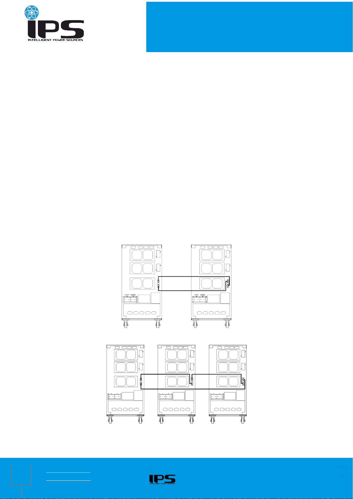
3.3.2 Parallel installation procedure
Install the parallel cables:when two UPS are paralleled, in order to ensure the reliability for parallel UPS units, there is
only one way to connect the parallel cables, it is to make the parallel cable connected in loop line, follow the method of
below drawing to connect the female port and male port, that is connecting two UPS with two parallel cables by parallel
cards. For three or more parallel UPS units, the quantity of parallel cables needed equals to the UPS quantities. It just
needs to connect each UPS in sequence with the parallel cables by parallel cards.
Parallel cable connection for two UPS
Parallel cable connection for three or more UPS
www.ips-ups.eu 28.05.2018
info@ips-ups.eu TS33-ON-manual_EN-R0
Page 11
SERIES TS33-ON
11
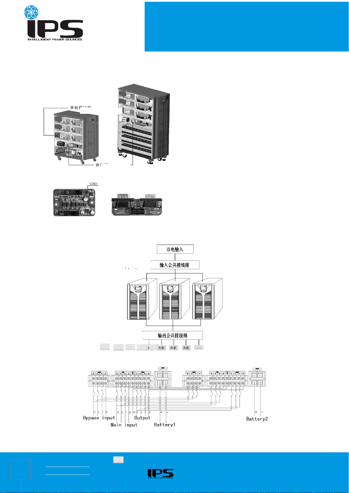
Public output terminal
Parallel port board
Parallel card
Load
Mains input
Public input terminal
Load
- - -
Load
Load
Load
Note: For three or more parallel UPS units, removing the jumper cap of CN3 on the parallel card of the more unit
than the third (including the third unit) is required, only keep the jumper cap of CN3 on the parallel card of the two
UPS.
Parallel card of long time mode UPS Parallel card of standard mode UPS
Short circuit cap of parallel card Parallel port board
Connect all parallel UPS output cables to the output patchboard, and connect wiring to the load from the output patchboard.
Connect all parallel UPS input cables to the input patchboard.
Parallel UPS connection
Two parallel UPS connection
www.ips-ups.eu 28.05.2018
info@ips-ups.eu TS33-ON-manual_EN-R0
Page 12

SERIES TS33-ON
12
For standard model UPS, each UPS has inbuilt battery group; for long time model UPS, it needs to equip separated
external battery group.
Verify all connection after parallel installation is completed. Operate the parallel UPS after confirming correct.
In the condition of each single UPS running, set the physical address (ID) of each UPS, and ensure that each ID is
different.
In the condition of each single UPS running, set the output voltage (OPU) of each UPS, and ensure that each OPU is
same.
Verify if the parallel cables of all UPS are connected firmly, perform startup and finish parallel installation.
www.ips-ups.eu 28.05.2018
info@ips-ups.eu TS33-ON-manual_EN-R0
Page 13

SERIES TS33-ON
13
4 Operation Instructions
4.1 Display panel
4.1.1 Buttons
Power ON button ( + )
Press the Power ON button more than half a second to turn the UPS on.
Power OFF button ( + )
Press the Power OFF button more than half a second to turn the UPS off.
Self Test / Mute button ( + )
In Mains / Frequency conversion / ECO mode, press and hold the buttons more than 1 second to perform UPS tests
and diagnostic functions.
In Battery / Failure / Self test mode, press and hold the buttons more than 1 second to mute the alarm; press and hold
the buttons more than 1 second again to cancel mute;
Inquiry button ( , )
In Non-menu setting interface:
Press or more than half a second and less than 2 seconds to display option contents in sequence from left to
right.
Press and hold more than 2 seconds to enter the history inquiry interface; press or more than half a
second and less than 2 seconds to turn the page of history records inquiring; press and hold again to return to the
main interface.
Press and hold more than 2 seconds to enter roll polling mode,display items are switched automatically in every 2
seconds. Press and hold again to return to the main interface.
In menu setting interface:
Press or more than half a second and less than 2 seconds to select setting options.
Menu settings button ( )
In Non-menu setting interface:
Press and hold more than 2 seconds to enter the menu settings interface.
In menu setting interface:
Press more than half a second and less than 2 seconds to confirm the setting option.
Press and hold more than 2 seconds to exit the menu setting interface.
4.1.2 LED indicators
www.ips-ups.eu 28.05.2018
info@ips-ups.eu TS33-ON-manual_EN-R0
Page 14

SERIES TS33-ON
14
Icon
s
Function
Description
Inverter
indicator
(Green)
Illuminated: The UPS is working in inverter
mode (such as mains power mode, battery
mode, battery self test mode, ECO mode,
frequency conversion mode).
Unilluminated: The UPS is working in noninverter mode.
Battery
indicator
(Yellow)
Illuminated: The UPS is working in battery /
battery self test mode.
Unilluminated: The UPS is working in nonbattery mode and non-battery self test mode.
Flash: low battery alarm
Bypass
indicator
(Yellow)
Illuminated: The UPS is working in bypass
mode or ECO mode.
Unilluminated: The UPS is working in nonbypass mode and non-ECO mode.
Flash: g in standby mode, not starting
frequency conversion and bypass abnormal
Alarm indicator
(Red)
Illuminated: UPS is faulty
Unilluminated: UPS is normal
Flash: the UPS emits an audible alarm
Date and
fault alarm
Value display and
menu settings area
Operation mode and
icons diplay area
Buzzer
Fault icon
Fan
4.1.3 LCD display
LCD display is divided into three areas: Operation mode and icons diplay area, value display and menu settings area
and date and fault alarm display area.
Operation mode and icons display area:
1) There are following contents in the area of display page
After starting up in 20 seconds, this display area mainly indicates the UPS power rating.
This display area mainly indicates the UPS operation mode in 20 seconds after starting up, such as STdby
www.ips-ups.eu 28.05.2018
info@ips-ups.eu TS33-ON-manual_EN-R0
Page 15

SERIES TS33-ON
15
Buzzer sound
Description
Long beep
Fault mode
1 s per beep
Low battery in battery mode
Output and bypass overload
2 minper beep
The inverter is not open
4 s per beep
All other alarms
(Standby mode), byPASS (Bypass mode), Line (Utility mode), bAT (Bttery mode), bATT (Bttery self test
mode), FAULT (Fault mode), CUCF (Frequency conversion mode), ECO (economy control operation), SHUTdn
(Shutdown mode), TEST (Test mode).
Fan icon indicates the working status of fans. Normally, the fan shows rotation status. The icon will flash if
fans are disconnected or faulty;
Buzzer icon indicates if the buzzer is mute. Normally, this icon doesn’t display. Press the mute button in
battery or fault mode or set backstage software set backstage software set backstage software set MUTE
ON in any mode, the UPS will get into mute status and the buzzer icon will be illuminated.
The fault icon is illuminated in fault mode, it doesn’t display in other cases.
2) The area of menu setting page showing the settable menu options
3) The area of event log query page showing page number of history records
Value display and menu settings area:
In non-menu setting interface, it indicates the relevant information of UPS. Press the inquiry button or
to display three phase mains circuit, three phase bypass, three phase output voltage, frequency, load,
battery voltage, capacity, backup time, temperature, Bus voltage, software version ect.
In menu setting interface, press the menu settings button and inquiry button to set output voltage value
(OPU), physical address(Id), end of discharge point (Eod), parallel Enable (PAL), checking status OFF
(CHK)、 Expert mode (EP), Clear warning function(CLRW)、Battery numbers(PCS)、Emergency
power off (EPO).
Press the inquiry button or to browse history records in history inquiry interface.
Date and fault alarm display area:
If there is no any fault alarm information, it indicates the system date. If there is alarm, it scrolls the display to indicate
current alarm information; If there is fault, it scrolls the display to indicate current fault information.
4.1.4 Equivalent UPS working status to the indicator
www.ips-ups.eu 28.05.2018
info@ips-ups.eu TS33-ON-manual_EN-R0
Page 16

SERIES TS33-ON
16
tem
Working status
The panel indicator display
Audible alarm
Normal
Battery
Bypass
Fault
1
Utility mode / Frequency conversion mode
No any fault alarm
● No
Alarm exists
● ★ 1/ 4 s per beep
2
Battery mode
Non-low battery
alarm
● ● ★ 4 s per beep
Low battery alarm
● ★ ★ 1 s per beep
3
Battery self test
mode / Starting
process
★ ★ ★ ★ 4 s per beep
4
Bypass mode
No any fault alarm
● 2 minper beep
Alarm exists
● ★ 1/ 4 s per beep
5
ECO mode
● ● No
Alarm exists
● ● ★ 1/ 4 s per beep
6
Fault mode
● Long beep
● _ The indicator is illuminated.
★ _ The indicator flashes.
4.2 UPS settings
Although the UPS settings can be configured in any mode, it is suggested that it should be better to make the
setting operation in standby mode. Contact with suppliers or after sales staff if need other configuration (frequency
conversion mode, ECO mode ON, parameter adjustment, special menu settings ect.)
www.ips-ups.eu 28.05.2018
info@ips-ups.eu TS33-ON-manual_EN-R0
Page 17

SERIES TS33-ON
17
4.2.1 Configure the UPS output voltage(OPU)
Output voltage setting interface
Press and hold the menu settings button more than 2 seconds to enter settings interface. Press inquiry button or
more than half a second and less than 2 seconds to select the function options. After selecting the output voltage
setup interface, OPU will flash.
Press the menu settings button more than half a second and less than 2 seconds to enter the output voltage setting
interface (OPU), at this moment OPU is illuminated, and the value under OPU flashes. Press inquiry button or
more than half a second and less than 2 seconds, select the corresponding values of OPU.There are 208V, 220V, 230V
and 240V available for options. The default output voltage is 220V. The configured settings can be saved in real time.
After selecting the value, press the menu settings button more than half a second and less than 2 seconds, OPU
setup is confirmed, at this moment the value under OPU is illuminated and stop flashing.
Press and hold the menu settings button more than 2 seconds to exit the setting interface and return to the home
screen.
Note: Configure the output voltage setting of parallel UPS units in standby or bypass mode. The settings of single
UPS unit can be configured in any mode.
www.ips-ups.eu 28.05.2018
info@ips-ups.eu TS33-ON-manual_EN-R0
Page 18

SERIES TS33-ON
18
4.2.2 Configure the end of discharge point(EOd)
end of discharge poin setting interface
Press and hold the menu settings button more than 2 seconds to enter the setting interface. Press inquiry button
or more than half a second and less than 2 seconds to select the function options. After selecting the EOd setting
interface, EOd will flash.
Press the menu settings button more than half a second and less than 2 seconds to enter the EOd setting interface,
at this moment EOd is illuminated, and the value under the EOd flashes. Press inquiry button or more than half a
second and less than 2 seconds to select the Eod value needed. There are dEF, 9.8V, 9.9V, 10V, 10.2V and 10.5V
available for options. EOd is dEF by default (Eod varies with load). The configured settings can be saved in real time.
After selecting the vaule, press the menu settings button more than half a second and less than 2 seconds, EOd
setup is confirmed, at this moment the selected value is illuminated and stop flashing.
Press and hold the menu settings button more than 2 seconds to exit the setting interface and return to the home
screen.
Note: The low voltage alarm point of each battery is (Eod + 1V) (Battery low voltage shutdown point +
1V)×Numbers of battery.
www.ips-ups.eu 28.05.2018
info@ips-ups.eu TS33-ON-manual_EN-R0
Page 19

SERIES TS33-ON
19
4.2.3 Configure the physical address (Id)
physical address setting interface
Press and hold the menu settings button more than 2 seconds to enter the setting interface. Press inquiry button
or more than half a second and less than 2 seconds to select the function options. After selecting the ID setting
interface, ID will flash.
Press the menu settings button more than half a second and less than 2 seconds to enter the ID setting interface, at
this moment ID is illuminated, and the value under the ID flashes. Press inquiry button or more than half a second
and less than 2 seconds to select the corresponding value of ID function. There are 1/2/3/4/5/6/7/8 available for options.
The default address is 1. The configured settings can be saved in real time.
After selecting the address, press the menu settings button more than half a second and less than 2 seconds, ID
setup is confirmed, at this moment the selected value is illuminated and stop flashing.
Press and hold the menu settings button more than 2 seconds to exit the setting interface and return to the home
screen.
Note: The physical address setting can be only configured in case of single UPS operating, it can not be done in
parallel UPS units
www.ips-ups.eu 28.05.2018
info@ips-ups.eu TS33-ON-manual_EN-R0
Page 20

SERIES TS33-ON
20
4.2.4 Configure parallel Enable(PAL)
parallel Enable setting interface
Press and hold the menu settings button more than 2 seconds to enter the setting interface. Press inquiry button
or more than half a second and less than 2 seconds to select the function options. After selecting the PAL Enable
setting interface, PAL will flash.
Press the menu settings button more than half a second and less than 2 seconds to enter the PAL Enable setting
interface, at this moment PAL is illuminated, and ON or OFF under the PAL flashes. Press inquiry button or more
than half a second and less than 2 seconds to select ON to use the PAL Enable function, select OFF not to use the PAL
Enable function. PAL is OFF by default. The configured settings can be saved in real time.
After selecting ON or OFF, press the menu settings button more than half a second and less than 2 seconds, PAL
Enable setup is confirmed, at this moment ON or OFF is illuminated and stop flashing.
Press and hold the menu settings button more than 2 seconds to exit the setting interface and return to the home
screen.
Note: The single UPS unit will emit an alarm indicating PAL SET F after PAL Enable. And it is forbidden to start the
UPS.
www.ips-ups.eu 28.05.2018
info@ips-ups.eu TS33-ON-manual_EN-R0
Page 21

SERIES TS33-ON
21
4.2.5 Checking status (CHK)
Checking status setting interface
Power up again after power off in fault mode, the UPS enters checking status (CHK). Judge if keep bypass output and
forbid turning on the UPS according to the fault information. It is not allowed to turn on the UPS until failure is solved and
manually close CHK.
Press and hold the menu settings button more than 2 seconds to enter the setting interface. Press inquiry button
or more than half a second and less than 2 seconds to select the function options. After selecting CHK setting interface,
CHK will flash.
Press the menu settings button more than half a second and less than 2 seconds to enter the CHK setting interface,
at this moment CHK is illuminated, and ON under the CHK flashes. Press inquiry button or more than half a
second and less than 2 seconds and select OFF, at this moment OFF flashes.
After selecting OFF, press the menu settings button more than half a second and less than 2 seconds, CHK Enable is
confirmed, at this moment OFF uner the CHK is illuminated and stop flashing.
Press and hold the menu settings button more than 2 seconds to exit the setting interface and return to the home
screen displaying UPS output information.
Power up again after power off, the UPS enter normal mode.
Note: The menu setting interface will not have CHK option until failure, there is no CHK option when the UPS is
normal.
www.ips-ups.eu 28.05.2018
info@ips-ups.eu TS33-ON-manual_EN-R0
Page 22

SERIES TS33-ON
22
4.2.6 Expert Mode(EP)
Expert mode is ON, then enter the menu settings page again, and there are three options available for setup: Clear
warning Enable (CLR W), numbers of battery, emergency power off (EPO). If Expert mode is OFF, these three
options will not be shown in the menu settings interface.
Expert Mode setting interface
Press menu setting button more than 2 seconds to enter the setting interface. Press inquiry button or
more than half a second and less than 2 seconds to select the menu, turn to Expert mode EP setting
page, EP will flash.
Press the enter button more than half a second and less than 2 seconds to enter Expert mode EP setting
interface, at this moment EP is illuminated, ON or OFF under EP flashes. Press inquiry button or more
than half a second and less than 2 seconds to select ON to use Expert mode, select OFF to turn off Expert
mode.By default, Expert mode is OFF.
Turn to page ON or OFF, press the enter button more than half a second and less than 2 seconds,
Expert mode setting is finished, at this moment ON or OFF under EP is illuminated and stop flashing.
Press menu setting button more than 2 seconds to exit the setting interface, and get back to the main
menu (or wait at most 30 seconds, it will automatically jump back to the main menu).
Note: Expert mode is OFF by default. After setting it to be ON, EP will be restored to be
OFF if power up again, but the setting contents of three options (CLR W, PCS and EPO) will be saved in real
time.
www.ips-ups.eu 28.05.2018
info@ips-ups.eu TS33-ON-manual_EN-R0
Page 23

SERIES TS33-ON
23
4.2.7 Clear warning Enable (CLR W)
When set EP as ON, CLR W option shows up in the setting interface, allows to clear away EEPROM abnormal,
ECO instability, Overload frequently, over temperature frequently, Mains high voltage unstable locking battery and
other alarms.
Clear warning Enable setting interface
Press menu setting button more than 2 seconds to enter the setting interface. Press inquiry button or
more than half a second and less than 2 seconds to selectthe menu, turn to CLR W setting page, CLR W
will flash.
Press the enter button more than half a second and less than 2 seconds to enter
CLR W setting interface, at this moment CLR W is illuminated, ON or OFF under
CLR W flashes. Press inquiry button or more than half a second and less than 2 seconds to select
ON to use Clear warning Enable function, select OFF to turn off Clear warning Enable.
Turn to page ON, press the enter button more than half a second and less than 2 seconds, CLR W
setting is finished, at this moment ON under CLR W is illuminated and stop flashing.
Press menu setting button more than 2 seconds to exit the setting interface, and get back to the main
menu (or wait at most 30 seconds, it will automatically jump back to the main menu).
www.ips-ups.eu 28.05.2018
info@ips-ups.eu TS33-ON-manual_EN-R0
Page 24

SERIES TS33-ON
24
4.2.8 Numbers of battery (PCS)
Numbers of battery setting interface
When set EP as ON, PCS option shows up in the setting interface, allows to configurate the number of batteries.
Press menu setting button more than 2 seconds to enter the setting interface. Press inquiry button or
more than half a second and less than 2 seconds to select the menu, turn to Numbers of battery (PCS)
setting page, PCS will flash.
Press the enter button more than half a second and less than 2 seconds to enter Numbers of battery
(PCS) setting interface, at this moment PCS is illuminated, numerical value under PCS flashes. Press inquiry
button or more than half a second and less than 2 seconds to select different physical address. There
are 14/16/18/20 pcs of batteries for options, and the settings will be saved in real time.
Turn to the page of battery numbers needed, press the enter button more than half a second and less
than 2 seconds, Numbers of battery (PCS) setting is finished, at this moment the numerical value under PCS
is illuminated and stop flashing.
Press menu setting button more than 2 seconds to exit the setting interface, and get back to the main
menu (or wait at most 30 seconds, it will automatically jump back to the main menu).
Note: After back-end software setting the model (TyPE), the number of batteries (PCS) will change
accordingly, if set the model as S, PCS will automatically turn to be the default value 20, if set the model as H,
PCS will automatically turn to be the default value 16.
www.ips-ups.eu 28.05.2018
info@ips-ups.eu TS33-ON-manual_EN-R0
Page 25

SERIES TS33-ON
25
4.2.9 Emergency power off (EPO)
Emergency power off setting interface
When set EP as ON, EPO option shows up in the setting interface, allows to configurate the
emergency power off.
Press menu setting button more than 2 seconds to enter the setting interface. Press inquiry button or
more than half a second and less than 2 seconds to select the menu, turn to Emergency power off (EPO)
setting page, EPO will flash.
Press the enter button more than half a second and less than 2 seconds to enter
EPO setting interface, at this moment EPO is illuminated, ON or OFF under EPO flashes.Press inquiry
button or more than half a second and less than 2 seconds to select ON to use emergency power off
(EPO) function, select OFF not to use emergency power off (EPO) function. By default, Emergency power off
(EPO) is OFF, and the settings will be saved in real time.
A. After setting EPO as OFF, press the enter button more than half a second and
less than 2 seconds, Emergency power off (EPO) setting is finished, at this moment
OFF is illuminated and stop flashing.
B. After setting EPO as ON, OP option under EPO ON shows up, and OFF behind OP flashes. Press
inquiry button or more than half a second and less than 2 seconds to select OP ON or OFF. OP ON
means bypass output after emergency power off. OP OFF means no output after emergency power off. The
settings will be saved in real time.
After setting OP as ON or OFF, press the enter button more than half a second and less than 2
seconds, Emergency power off (EPO) setting is finished, at this moment OFF is illuminated and stop flashing.
Press menu setting button more than 2 seconds to exit the setting interface, and get back to the main
menu (or wait at most 30 seconds, it will automatically jump back to the main menu).
Note: After setting OP OFF, the output power fails when emergency power shut off.
www.ips-ups.eu 28.05.2018
info@ips-ups.eu TS33-ON-manual_EN-R0
Page 26

SERIES TS33-ON
26
4.3 Parameters inquiry
Press inquiry button or more than half a second and less than 2 seconds to inquire in sequence for some
information about three-phase A / B / C main input, bypass, output, load, frequency, software version, temperature, battery,
Bus voltage ect., 5 pages in total.
Press and hold inquiry button more than 2 seconds to enter roll polling mode display, automatically switch display
items in every 2 seconds, and go back to the default status displaying phase A information in 30 seconds. If press and hold
again within 30 seconds, it will go back to the main interface immediately
InterfacePage 1 (main interface): Display UPS phase A information, as shown below
InterfacePage 2: Display UPS phase B information, as shown below
InterfacePage 3: Display UPS phase C information, as shown below
InterfacePage 4: Display UPS frequency information, temperature and software version, as shown below:
www.ips-ups.eu 28.05.2018
info@ips-ups.eu TS33-ON-manual_EN-R0
Page 27

SERIES TS33-ON
27
Time
Fault code
Page
InterfacePage 5: Display UPS battery voltage, battery capacity percentage, BUS voltage, as shown below:
4.4 Event log query
Press and hold the inquiry button more than 2 seconds to enter Event log query interface; Press inquiry button
or more than half a second and less than 2 seconds to look over event logs with page turning. There are
maximum 200 pages (600 pieces) event logs records. Press and hold the inquiry button more than 2 seconds
again to return to the home screen.
Event logs query is for qualified personnel use only.
www.ips-ups.eu 28.05.2018
info@ips-ups.eu TS33-ON-manual_EN-R0
Page 28

28
Operatio
n
Description
Turn on the
UPS
When proper battery or main input is connected, the UPS
can be turned on.
Turn on the UPS by mains power
Connect normal mains input, LCD panel displays STdby
or bypass, press Power ON button + more than
half a second to turn the UPS on. LED indicator is
illumined circularly in turn and lights go out in turn. After
waiting for a while until the display panel showing LinE
or bAT, turning on the UPS is completed and enter
mains power mode.
Turn on the UPS by batteries
Connect normal batteries, press menu setting/enter
button more than half a second, the display screen
is illumined, and display STdby, UPS has workign power
supply, then press Power ON button + more
than half a second to turn the UPS on. LED indicator is
illumined circularly in turn and lights go out in turn. After
waiting for a while until the display panel showing bAT,
turning on the UPS is completed and enter battery mode
。
Turn off
the UPS
In Mains power / battery mode / battery self test / ECO /
frequency conversion mode, press Power OFF button
+ more than half a second to turn off the UPS. If
bypass is normal, UPS panel displays byPASS to enter
bypass mode, if bypass is abnormal, UPS panel
displays STdAby to enter standby mode. If turn off the
UPS in bypass mode, UPS enter to standby mode.
Self-test
operation
In Mains power / ECO / frequency conversion mode,
press Self Test / Mute button + more than 1
second and wait 10 seconds, LED indicator is illumined
circularly in turn and lights go out in turn, LCD display
bATT, the UPS enters battery self test mode and
automatically quit after finishing diagnosing, and then
LED and LCD restore previous state.
Mute
operation
In battery / battery self test / fault mode, press Self Test
/ Mute button + more than 1 second, UPS panel
displays buzzer disable icon, the alarm buzzer will
silence. If press Self Test / Mute button + more
than 1 second again, the buzzer starts beeping, the
buzzer disable icon is eliminated.
In any modes, MUTE ON is configurable by LCD panel
4.5 UPS On / Off operation
SERIES TS33-ON
www.ips-ups.eu 28.05.2018
info@ips-ups.eu TS33-ON-manual_EN-R0
Page 29

29
to make the UPS mute.
Note: It is not allowed to make the UPS mute in low
battery; if setting mute in fault mode, the mute will be
automatically cancelled in one day, and troubleshooting
soon is required.
Operatio
n in
audible
alarm
status
When the buzzer is beeping or the fault indicator is
flashing, it indicates that the UPS is in alarm status,
troubleshooting can be done by the alarm information
displayed on the LCD panel.
Operatio
n in fault
mode
When the sound of the UPS buzzer lingers on and the
fault indicator is illuminated, it indicates that the UPS
enter fault mode, contact your supplier or serviceman
and provide them with failure information.
Pins 1 2 3 4
5
Definitio
n
Empty
Transmi
t
Receive
Empty
GND
Pins 6 7 8 9
Definitio
n
Empty
Empty
Empty
Empty
Pins 1 2 3 4
Definitio
n
Power
source
+ 5 V
Data
+
Data -
GND
In normal condition, pins ① and pins ② are closed;
4.6 Connect the communication
4.6.1 Computer port
SERIES TS33-ON
Connect the UPS and monitoring equipment (computer) by standard RS232 port (standard configuration) and
standard USB port (standard configuration) to make single unit communication.
Connect RS232 (or USB) cable to the serial port of the computer (or USB port)
Connect RS232 (or USB) cable to the serial port of the UPS (or USB port)
RS232 port
USB port
4.6.2 EPO port
The Emergency Power Off (EPO) is a feature that will immediately disconnect all connected equipment from mains
power. The EPO port is on the rear panel of the UPS with green terminals. Its connection is as follows:
www.ips-ups.eu 28.05.2018
info@ips-ups.eu TS33-ON-manual_EN-R0
Page 30

SERIES TS33-ON
30
Pin
s
Definition
PIN
1
Close:UPS fault
PIN
2
Close:Alarm sounds (system
fault)
PIN
3
Grounding
PIN
4
Remote shutdown
PIN
5
Common
PIN
6
Close:bypass working
PIN
7
Close:low battery
PIN
8
Close:UPS working
Open:bypass working
PIN
9
Close: Mains power Off
4.6.3 Intelligent cards (optional)
The UPS has two intelligent slots for SNMP card (upper slot), dry contacts card and RS485 card (lower slot).
Intelligent cards are installed in the intelligent slots on the UPS rear panel, and there is no need to stop the UPS
during installation. The installation procedure is as follows:
Remove the cover plate of the intelligent slots
Insert the required intelligent card into the slot
Tighten the screws
SNMP card (optional)
SNMP is used in network management systems to communicate, manage and monitor UPS devices, it could be
compatible with current popular software , hardware and network operating system.
Dry contacts card (optional)
Insert dry contacts card into the intelligent slot to monitor and manage the UPS.
RS485 card (optional)
A and B on the right side of ports are RS485 output, A is “+”,
B is “-”.
4.6.4 Maintenance switch
Maintenance switch is for UPS on- line maintenance, follow below
procedures:
Open the cover plate of the maintenance switch on the UPS rear
panel, the UPS will automatically transfer to byass to supply power to
the load.
Make the maintenance switch at “BYPASS”.
Disconnect all input / battery breaker.
Wait until the disply screen is extinguished completely and on standing for 10 mins, make sure there is no hazard of
electrical shock inside the UPS, and you can do on-line maintenance for the UPS.
After finishing on-line maintenance, close the input breaker first, then make the maintenance switch at “UPS” end, and
www.ips-ups.eu 28.05.2018
info@ips-ups.eu TS33-ON-manual_EN-R0
Page 31

SERIES TS33-ON
31
then install the cover plate of the maintenance switch.
Note: Make sure the system bypass is normal and not to start frequency conversion, otherwise it may cause power
failure or even damage to loads.
If the UPS has no output and needs manual on-line maintenance, disconnect all input breaker and ensure the
UPS display screen is extinguished, then put the maintenance switch to “BYPASS” by hand, otherwise it may
cause damage to the UPS.
4.7 Parallel UPS operation
Follow single UPS operation requirements for general operation of parallel system. Before turning on the
parallel UPS units, setting the physical address (ID) of each UPS is required, ensure each ID is different. Refer
to panel settings operation for setting method details.
4.7.1 Start up parallel UPS
Startup with mains power:After access mains power, press the Power ON button + of any one of
UPS more than half a second to start up parallel UPS. All UPS units will be turned on at same time, then
meanwhile switch to inverter status, working in mains power mode.
Startup with the battery: Method 1: press first key of each UPS, after each UPS having working power
source, press the Power ON button + of any one of UPS more than half a second to start up parallel
UPS. All UPS units will be turned on at same time, then meanwhile switch to inverter status, working in mains
power mode. Method 2: Execute startup operation on each UPS one by one.
4.7.2 Shut down parallel UPS
Keep pressing the Power OFF button + of any one of UPS more than 4 seconds to turn off parallel UPS
units; press the Power OFF button + of any one of UPS more than half a second and less than 4
seconds to turn off the single UPS unit.
4.7.3 Parallel UPS system maintenance
Follow single UPS maintenance requirements for parallel system maintenance. If one of parallel system UPS
fails and need to maintain it, firstly it is required to cut off the breaker between input / output of the faulty UPS
and parallel system, ensure that there is no electrical connection for the faulty UPS and parallel system, then
disconnect all parallel cables of the faulty UPS and parallel system, and then make maintenance operation for
the faulty one.
www.ips-ups.eu 28.05.2018
info@ips-ups.eu TS33-ON-manual_EN-R0
Page 32

SERIES TS33-ON
32
维修旁路
Maintenance bypass
5 Operation Modes
This UPS is a kind of on-line dual conversion UPS, which has following operation modes:
Power-up mode (LCD display power capacity)
Standby mode (Stdby)
Bypass mode (byPASS)
Mains power mode (LInE)
Battery mode (bAT)
Battery self test (bATT)
Fault mode (FAULT)
Frequency conversion mode (CUCF)
Economy control operation (ECO)
Shutdown mode (SHUTdn)
Test mode (TEST)
Maintenance bypass mode (manual operation)
5.1 Power-up mode / Shutdown mode
In the condition of power off and the display screen being black out, connect batteries and press first key or
connect mains power or connect bypass to illuminate the screen, the UPS gets into power-up mode, all illuminated
LED indicators are turned into off (as shown in the figure below), meanwhile LCD display power capacity
(10kVA/15kVA/20kVA/30kVA).
In standby mode, the UPS detects that mains power and bypass three phase all are less than 85 V, it will delay 1
min to automatically enter shutdown mode, all LED indicators are turned off, meanwhile LCD display SHUTdn
characters.
5.2 Standby mode
There is no output voltage in standby mode. If mains circuit input is normal, then automatically process AC / DC
rectification, after rectificating automatically start the charger charging batteries.
All LED indicators are turned off in standby mode operation (as shown in the figure below), meanwhile LCD display
Stdby characters.
There are several situations as follows to enter standby mode:
Bypass is abnormal after the UPS is powered up (including frequency conversion enable) and the UPS isn’t turned on.
In mains power mode / battery mode / frequency conversion mode, shut down the UPS when bypass is abnormal
Shut down the single UPS unit when inverter of parallel UPS units is operating
Exit fault mode and byass is abnormal
www.ips-ups.eu 28.05.2018
info@ips-ups.eu TS33-ON-manual_EN-R0
Page 33

SERIES TS33-ON
33
AC / DC
整流
充电器
DC / DC
升压
电池
+
-
DC / AC
逆变
Mains circ
input
Bypass Input
Charger
Battery
AC / DC
rectifier
DC / DC boost
DC / AC inverter
Bypass input
Mains circuit
input
output
Standby mode operation process
5.3 Bypass mode
In bypass mode, mains power of bypass input goes through the filter to the load. If mains circuit input is normal,
then automatically process AC / DC rectification, after rectificating automatically start the charger charging
batteries.
LED indicator in bypass mode is as shown in the figure below (white color indicates illuminated status), meanwhile
LCD display byPASS characters.
There are two situations as follows to enter bypass mode:
Bypass is abnormal after the UPS is powered up (including frequency conversion enable) and the UPS isn’t turned on.
Shut down in mains power mode, overload or overtemperature
Exit fault mode and bypass are normal
When bypass is normal, turn off the UPS or the inverter circuit has failure, the UPS transfer to bypass mode to
supply uninterruptible power to the load.
Note: Bypass mode doesn’t have function of backup.
BYPASS MODE OP ERATION PROCESS
5.4 Mains power mode (Frequency conversion mode)
In mains power mode, the mains power from mains circuit input supply AC power to the UPS rectification, and
supply DC power to the inverter circuit after PFC power factor correction, and then supply uninterruptible AC power
to the load via the inverter circuit. After the inverter startup, automatically start the charger charging batteries.
LED indicator in mains power mode is as shown in the figure below: the inverter LED indicator (green) is
illuminated, meanwhile LCD display LinE characters.
www.ips-ups.eu 28.05.2018
info@ips-ups.eu TS33-ON-manual_EN-R0
Page 34

SERIES TS33-ON
34
AC/DC 整流
充电器
DC/DC 升压
电池
+ -
DC/AC 逆变
输出
旁路输入
维修旁路
主路输入
Maintenance bypass
Bypass input
Mains circuit
input
AC / DC rectifier
DC / DC boost
DC / AC inverter
Battery
Charger
output
Note: The inverter output frequency in frequency conversion mode is configured output frequency and cutting off
bypass is necessary; the inverter output frequency in mains power mode is related to bypass frequency (the default
is 50 Hz when bypass is abnormal and frequency conversion disenable). Please contact with supplier or after sales
staff if need to set frequency conversion mode.
MAINS POWER MODE OPERATION PROCESS
5.5 Battery mode / battery self test mode
In battery mode, the batteries go through DC / DC boost and supply DC voltage to the inverter, and then supply AC
power to the load via the inverter circuit.
LED indicator in battery mode is as shown in the figure below: the inverter LED indicator (green) is illuminated and
battery LED indicator (yellow) is illuminated, and alarm LED indicator (red) flashes while giving alarm, meanwhile
LCD display bAT characters.
When the batteries process in manual self-test and regular self-test, the inverter indicator, bypass indicator, battery
indicator and fault indicator will be illuminated circularly, meanwhile LCD display bAT characters.
When the mains circuit input is abnormal, the UPS transfers to battery modeimmediately. When the battery voltage
is less than shutdown point and bypass is normal in battery mode, the UPS transfers to bypass mode to supply
uninterruptible power to the load.
5.6 ECO mode
LED indicator in ECO mode is as shown in the figure below: the inverter.LED indicator (green) is illuminated and
bypass LED indicator (yellow) is illuminated, meanwhile LCD display ECO characters.
Battery mode / battery self test modeoperation process
www.ips-ups.eu 28.05.2018
info@ips-ups.eu TS33-ON-manual_EN-R0
Page 35

SERIES TS33-ON
35
AC/DC 整流
充电器
DC/DC 升压
电池
+ -
DC/AC 逆变
输出
主路输入
维修旁路
旁路输入
P-1
Maintenance bypass
Bypass input
Mains circuit
input
AC / DC rectifier
DC / DC boost
DC / AC
inverter
Battery
Charger
output
When bypass input meets ECO input range and ECO function come to use, the UPS works in ECO mode. At this
time bypass supply power to the load, meanwhile rectification, boosting and inverter work normally, and the
charger charges the batteries. When bypass input is out of ECO range, the UPS transfers to mains power / battery
mode operating.
If bypass input is beyond ECO range for five times within 1 hour, the UPS operates time after time from ECO mode
to mains power mode, the UPS will automatically operate inmains power mode and close ECO function.
Note: When use ECO mode and ECO transfers to inverter, the output probably break off 20ms. For those loads
which require strict transfer time, be cautious to choose whether start ECO mode or not. Please contact with
supplier or after sales staff if need to set economy control operation.
ECO M ODE OPERATION PR OCESS
5.7 Fault mode
LED indicator in fault mode is as shown in the figure below: alarm LED Indicator (red) is illuminated, meanwhile LCD display fault icon and fault
code.
When UPS is faulty, the alarm indicator is illuminated, the sound of the UPS buzzer lingers on. According to fault
type, fault mode is divided into the fault of cutting off output and the fault of bypass output.
Cut off output after failure in following status:
Short circuit fault of output A / B / C phases voltage
Short circuit fault of output AB / BC / CA line voltage
Beyond 165% overload
EPO fault of configured cutting off output
Any fault when bypass is abnormal
Keep bypass supplying power to the load for other faults beyond above status.
After the UPS enter fault mode, press mute button to mute the sound (auto cancel mute in one day), meanwhile
contact your supplier or serviceman for troubleshooting.
www.ips-ups.eu 28.05.2018
info@ips-ups.eu TS33-ON-manual_EN-R0
Page 36

SERIES TS33-ON
36
AC/DC 整流
充电器
DC/DC 升压
电池
+ -
DC/AC 逆变
输出
主路输入
维修旁路
旁路输入
Maintenance bypass
Bypass input
Mains circuit
input
AC / DC
rectifier
DC / DC boost
DC / AC
inverter
Battery
Charger
output
OPERATION PROCESS FOR FAULT MODE OF BYPA SS OUTPUT
5.8 Maintenance bypass (manual operation)
When UPS is faulty or need on-site maintenance, qualified personnel will manually switch the UPS to maintenance
bypass mode. At this time mains power of bypass input supply power to the load directly, there is no electricity
inside the UPS for maintenance operation.
Note: Make sure the system bypass is normal and not to start frequency conversion, otherwise it may cause power
failure or even damage to loads.
If the UPS has no output and needs manual operation on maintenance switch, please ensure to disconnect all
input breaker and the UPS display screen is extinguished completely, then put the maintenance switch to
“BYPASS” by hand, otherwise it may cause damage to the UPS.
Refer to 4.6.4 for details.
5.9 Test mode
Test mode is specially used for test purpose, It is available to control UPS step-startup and drive test ect. by backend software.
www.ips-ups.eu 28.05.2018
info@ips-ups.eu TS33-ON-manual_EN-R0
Page 37

37
6 Troubleshooting
Possible Cause
Solution
The fault indicator is
illuminated, the sound of
the buzzer lingers on,
and emits fault
information bUS
HIgH/bUS LOW/bUS
UnbAL/bUS SHORT
Bus voltage fault
Test the bus voltage or
contact the supplier.
The fault indicator is
illuminated, the sound of
the buzzer lingers on,
and emits fault
information - IPSOFT
F/bUSSOFT F
Soft start fault
Check the soft start circuit
or contact the supplier
directly.
The fault indicator is
illuminated, the sound of
the buzzer lingers on,
and emits fault
information - InU
HIgH/InU LOW/InU
FAIL/InUSOFT F
Inverter voltage fault
Contact the supplier.
The fault indicator is
illuminated, the sound of
the buzzer lingers on,
and emits fault
information - OUER
TEMP
Over temperature
inside
Be sure that the UPS are
not overloaded, and the fan
vent is not obstructed, as
well as the indoor
temperature is not high.
Leave alone the UPS 10
minutes for cooling, and
restart it. If the problem
persists, contact the
supplier.
The fault indicator is
illuminated, the sound of
the buzzer lingers on,
and emits fault
information - AOP
SHORT/BOP
SHORT/COP
SHORT/AB SHORT/BC
Output short-circuit
Turn off the UPS and
disconnect all the loads. Be
sure there is no any fault or
internal short circuit of the
loads. And then restart the
UPS. If the problem
persists, contact the
supplier.
Fault mode
Fault
LCD display in fault mode is as shown below:
SERIES TS33-ON
www.ips-ups.eu 28.05.2018
info@ips-ups.eu TS33-ON-manual_EN-R0
Page 38

SERIES TS33-ON
38
SHORT/CA SHORT
The fault indicator is
illuminated, the sound of
the buzzer lingers on,
and emits fault
information - OUER
LOAd
Overload
Check the load level and
disconnect the non-critical
equipments, recount the
total capacity of your load
and reduce the load to the
UPS.
Check whether the load
equipments has fault or not.
The fault indicator is
illuminated, the sound of
the buzzer lingers on,
and emits fault
information - AnEgPOW
F/BnEgPOW
F/CnEgPOW F
Negative power is
abnormal
Contact the supplier.。
Fan icon flashes, the
buzzer beeps in every 4
seconds, and emits
alarm information- FAn
FAIL
Fan fault
Check whether the fans are
connected and fixed well or
not and whether they are
broken or not. If all seems
fine, contact the supplier.
The UPS fails to start
when press ‘On’ key
Pressing time too
short
Press the power key more
than 2 seconds to start the
UPS.
The input connection
is not ready or UPS
internal battery
disconnected
Connect the input well, if
the battery voltage is too
low, disconnect the input
and start the UPS with no-
load.
Internal system fault
Contact the supplier.
The battery discharge
time is too short
Battery undercharge
Keep the UPS battery
recharging more than 3
hours
UPS overload
Check the load level and
disconnect the non-critical
equipments.
Battery maturing,
capacity descend
Replace with new batteries,
contact the supplier to get
the new batteries and spare
parts.
The mains power is
normal but the UPS fails
to access to mains
power
UPS input fuse is
disconnected or
input wiring is wrong
Replace with new fuse or
check input manner or
contact the supplier
www.ips-ups.eu 28.05.2018
info@ips-ups.eu TS33-ON-manual_EN-R0
Page 39

SERIES TS33-ON
39
Note: Contact the supplier if display screen shows other fault information. After troubleshooting, power-up need to
enter menu setting interface to configure CHK OFF, refer to 4.2.8 for operation details.
www.ips-ups.eu 28.05.2018
info@ips-ups.eu TS33-ON-manual_EN-R0
 Loading...