

IPS IPS600-SIN-WM, IPS300-SIN-WM, IPS600-SIN-DC, IPS1000-SIN, IPS1000-SIN-DC User Manual
...Page 1
IPS home inverter manual
www.ips-ups.eu 4.09.2017
info@ips-ups.eu IPS-home-inverter-manual_ENG-R1
1
USER MANUAL
IPS home inverters with UPS function
Suitable for UPS:
- IPS300-SIN
- IPS300-SIN-WM
- IPS300-SIN-DC
- IPS600-SIN
- IPS600-SIN-WM
- IPS600-SIN-DC
- IPS1000-SIN
- IPS1000-SIN-DC
- IPS1600-SIN
- IPS1600-SIN-DC
- IPS2500-SIN
- IPS3500-SIN
Page 2

IPS home inverter manual
www.ips-ups.eu 4.09.2017
info@ips-ups.eu IPS-home-inverter-manual_ENG-R1
2
Table of Contents
1 Safety Information .............................................................................................. 1
2 Product Overview ............................................................................................... 4
2.1 Specifications ............................................................................................... 4
2.2 Front panel features ..................................................................................... 6
2.3 Rear panel features ..................................................................................... 6
3 Installation Instructions ..................................................................................... 8
3.1 Unpacking Inspection.. ................................................................................. 8
3.2 Installation .................................................................................................... 8
4 Operations ......................................................................................................... 10
4.1 Turn the inverter On/Off ............................................................................. 10
4.2 Display interface ........................................................................................ 10
4.3 Settings ...................................................................................................... 10
4.4 Troubleshooting ......................................................................................... 13
Page 3
IPS home inverter manual
www.ips-ups.eu 4.09.2017
info@ips-ups.eu IPS-home-inverter-manual_ENG-R1
3
Models quick description
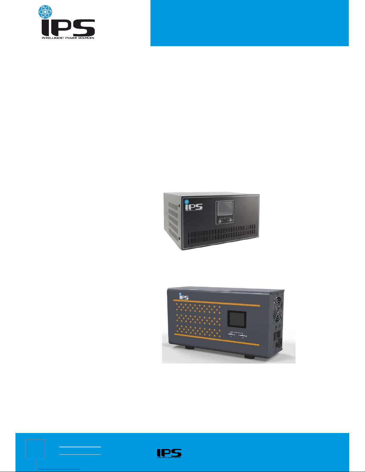
IPS300-SIN
Standalone metal
case
IPS300-SIN-DC
Standalone metal case
with DC output and PV
input
IPS600-SIN
IPS600-SIN-DC
IPS1000-SIN
IPS1000-SIN-DC
IPS1600-SIN
IPS1600-SIN-DC
IPS2500-SIN
IPS300-SIN-WM
Wall mounted metal case
IPS3500-SIN
IPS600-SIN-WM
1 Safety Information
CAUTION
Non-qualified electricians are forbidden to open the case due to hazard of
electrical shock.
Consulting the dealer is required before using for below equipment. Its
application, configuration, management and maintenance must be specially
considered and designed.
Medical equipment which is directly related to patients’life
Elevator and other equipment which may endanger personal safety
Safety and General Information
Read all safety information and operating instructions carefully before attempting to install, operate, service or maintain the
inverter.
Do not disassemble this inverter. Contact your local service center if maintenance or repair is needed.
Disconnect all connection wiring before maintenance or cleaning to avoid the risk of electric shock.
Do not use liquid extinguisher if there is a fire, a dry powder extinguisher is recommended.
Do not dispose of the batteries with fire. The batteries may explode.
Do not open or mutilate batteries. Released electrolyte inside is harmful to the skin and eyes, and maybe toxic.
Do not connect the positive pole and negative pole directly, otherwise it will cause electric shocks or will be on fire.
Page 4
IPS home inverter manual
www.ips-ups.eu 4.09.2017
info@ips-ups.eu IPS-home-inverter-manual_ENG-R1
4
2 Product Overview
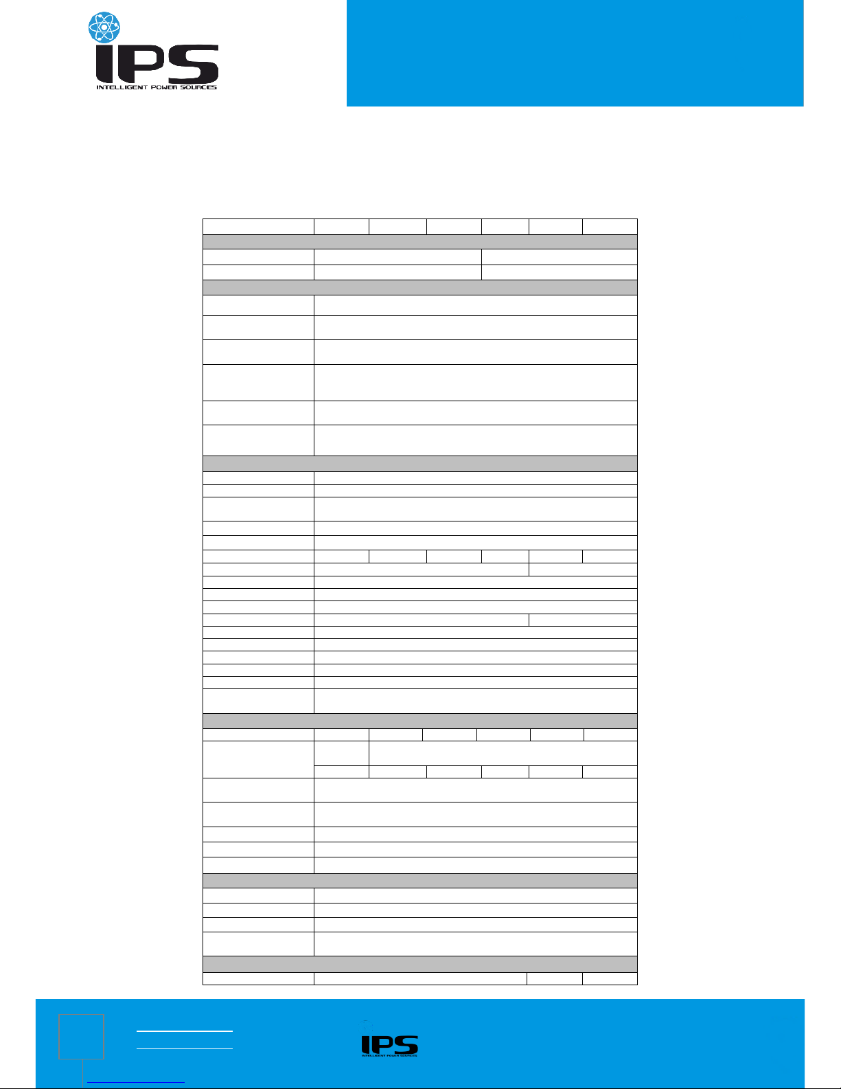
2.1 Specifications
MODEL
300W
600W
1000W
1600W
2500W
3500W
DC Input (the inverter must be connected to batteries to work properly)
Nominal input voltage
12V
24V
DC input range
10 ~ 15V
20 ~ 30V
AC Input
Bypass input range
0 ~ 264Vac for 220Vac/230Vac/240Vac,
Mains input range
150 ~ 282Vac for 220Vac; 156 ~ 294Vac for 230Vac;
163 ~ 307Vac for 240Vac;
Input frequency range
50Hz / 60Hz (Auto-sense& Settable:5% ~15%,default 15%),
42.5 ~ 57.5Hz for 50Hz, 51 ~ 69Hz for 60Hz
Input range of the
generator
99 ~ 282Vac for 220Vac; 104 ~ 294Vac for 230Vac;
108 ~ 307Vac for 240Vac;
No AVR in generator mode
Input frequency range
of the generator
40 ~ 70Hz
Input power matching
of the generator
Rated power 10% ~ 150%,
regulating step 10%,default 120%
Output
Inverter output range
220Vac / 230Vac / 240Vac ± 5% or
Bypass output range
0 ~ 264Vac for 220V/230V/240V,
Mains output range
174 ~ 242Vac for 220Vac; 182 ~ 253Vac for 230Vac;
190 ~ 264Vac for 240Vac;
Output frequency
50Hz / 60Hz ± 0.3 (Auto-sense & settable)
Output waveform
Pure sine wave
Output power
300W
600W
1000W
1600W
2500W
3500W
Putput sockets
2x schuko CEE 7/3
Block terminal
Efficiency
Max. 95% (Mains mode); Max. 80% (Inverter mode)
ECO mode
Settable, load<3%,enter in 80 s
No-load shutdown
Settable, time can be set (1 ~ 99 min), load can be set (3% ~ 50%)
Transfer time
≤ 10 ms
≤ 15 ms
Power factor
1.0
THDV
< 5% (linear load)
Inductive load
Yes
Motor load
Yes
Rectifier load
Yes
Overload capability
Mains mode: 110% 120 s; 125% 60 s; 150% 10 s (switch to bypass)
Inverter mode: 110% 60s; 125% 10 s; 150% 10s (shut down)
Battery
String battery q-ty
1 1 1 2 2
2
Charging current
(selectable)
Default
10A
Default 20A, regulating step 1A (< 10A) / 5A (> 10A)
Max. 15A
Max. 30A
Max. 40A
Max. 40A
Max. 50A
Max. 60A
Equalizing charge
voltage
Single battery 14.4Vdc (default), 13.6 ~ 15Vdc settable
Floating charge
voltage
Single battery 13.7Vdc (default), 13.2 ~ 14.6Vdc settable
DOD
Single battery 10.8Vdc (default), 9.6 ~ 13Vdc settable
EOD
Single battery 10.2Vdc (default), 9.6 ~ 11.5Vdc settable
Reverse warning
Buzzer
Alarm
Switch on / off
Continuous beep 2 s
Low battery
Beep 0.2 s at interval of 0.4 s
Overload
Beep 2 s at interval of 2.5 s
Mains power
abnormal
Beep 0.3 s at interval of 5 s
MPPT Modules (for –DC series only)
Model
40A
/
/
Page 5

IPS home inverter manual
www.ips-ups.eu 4.09.2017
info@ips-ups.eu IPS-home-inverter-manual_ENG-R1
5
Max. PV input
voltage(Voc)
40 V
60 V
/
/
PV optimum operating
voltage(Vmp)
18 V ~ 32 V
29V ~ 48 V
/
/
Max.PV. power
120W / 240W /
360W / 480W
240W / 480W /
720W / 960W
/
DC Outputs (for –DC series only)
Model
5V (2A), 9V / 12V (1A), 15V / 24V (1A),
2pin socket: 12V (10A)
Other
1x PoE, 2x USB 5B (2A)
Others
Protections
Overload – short-circuit – overvoltage – undervoltage – overcharge –
overtemperature – excessive low battery – missing insert
Interface
LCD & BUZZER
Operating
temperature
0℃ ~ 40℃
Operating humidity
Relative humidity ≤ 93%
Altitude
< 1000m, (above 1000m, derating 1% for each additional 100 m),
4000 m max.
Net weight (kg)
8.0/8.5/7.4
10.9/11.4/11
14.0/14.6
18.0/18.5
32.0
36.0
Gross weight (kg)
9.0/9.5/8.4
11.9/12.4/12
15.0/15.6
19.0/19.5
34.0
38.0
Dimensions (W×D×H)
mm
280×258×120 (w/o option)
293×280×160 (w/ option)
400×210×127 (Wall
mounted)
293×280×160
302×479×209
Packaged dimensions
(W×D×H) mm
330×352×200 (w/o option)
370×355×235 (w/ option)
490×290×195 (Wall
mounted)
370×355×235
353×582×287
Note: Specifications are subject to change without notice;MPPT modules and DC modules are optional.
Charging features
Charging
process
Three-stage:
CC (constant current) CV (constant voltage) Float (floating charge)
Process
diagram
Constant voltage charging time: 60 S
Page 6

IPS home inverter manual
www.ips-ups.eu 4.09.2017
info@ips-ups.eu IPS-home-inverter-manual_ENG-R1
6
2.2 Front panel features
300W ~ 1600W front panel 300W ~ 600W front panel
Tower type Wall mounted type
2500W ~ 3500W front panel
2.3 Rear panel features
300W ~ 1600W rear panel
① AC input socket
② Output sockets
③ Overcurrent protector
④ Buzzer for battery reverse
⑤ Battery wiring
⑥ Battery breaker
⑦ Fan
Tower type
Wall mounted type
Page 7

IPS home inverter manual
www.ips-ups.eu 4.09.2017
info@ips-ups.eu IPS-home-inverter-manual_ENG-R1
7
⑧ DC output fuse
⑨ MPPT (optional)
⑩ DC output (optional)
Optional model (with MPPT / DC modules)
2500W ~ 3500W rear panel
① Input/output terminal block
② Overcurrent protector
③ Battery breaker
④ Buzzer for battery reverse
⑤ Battery wring terminal
⑥ Fan
Page 8
IPS home inverter manual
www.ips-ups.eu 4.09.2017
info@ips-ups.eu IPS-home-inverter-manual_ENG-R1
8
3 Installation Instructions
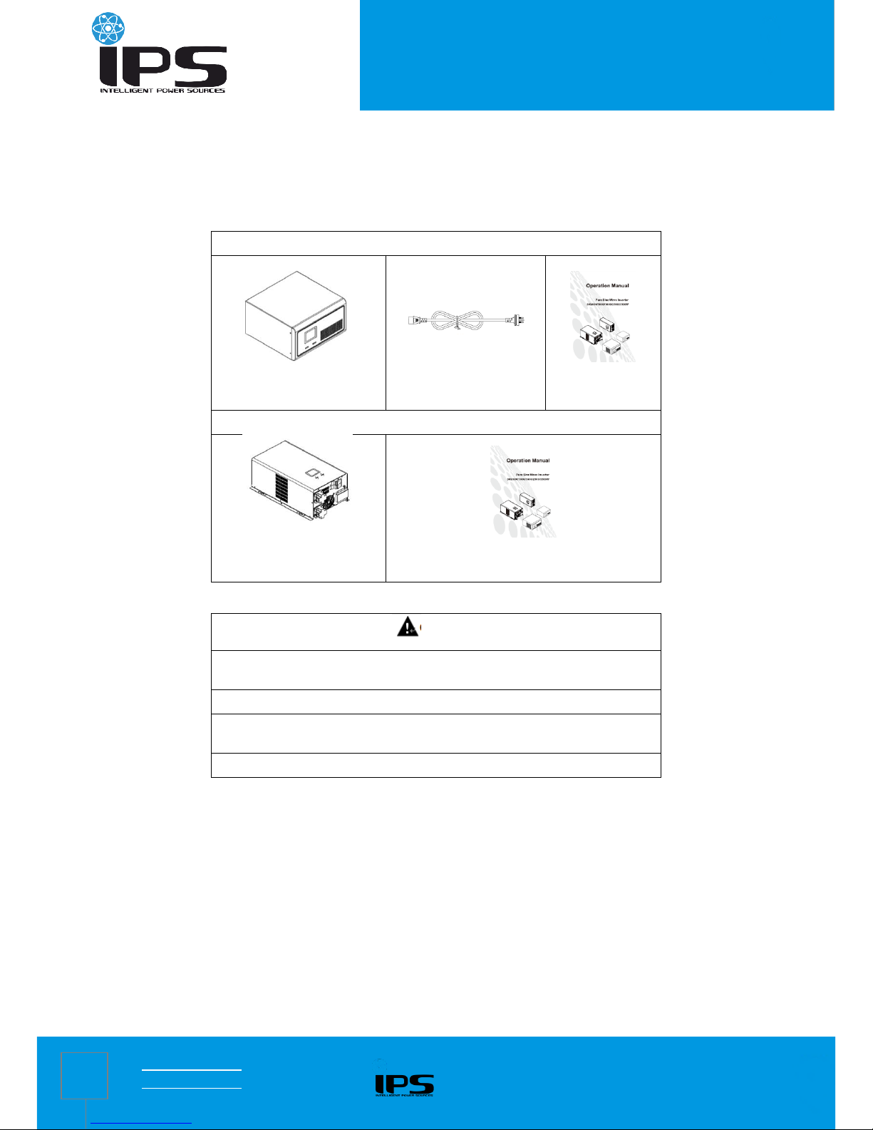
3.1 Unpacking inspection
Inspect the contents upon receipt. Notify the carrier and dealer if the unit is damaged.
300W ~ 1600W package contents
300W ~ 1600W Inverter
AC input power cords
Operation manual
2500W ~ 3500W package contents
2500W ~ 3500W Inverter
Operation manual
3.2 Installation
CAUTION
The inverter is designed for indoor use. Do not operate this UPS in direct
sunlight, in contact with fluids, or where there is excessive dust or humidity.
Place batteries in sound ventilation environment.
Use insulated tools to reduce the risk of short-circuit when installing or working
with the inverter, the batteries, or other equipments attached to this unit.
Be sure that the ground terminal has been connected with the ground.
3.2.1 Installation information
Inspect whether the battery voltage and Mains voltage are correct or not.
Connect the inverter with batteries, utility power and loads. Be sure all wiring is correct, terminals are screwed tightly and
terminal cover is locked.
Open the battery breaker, press ON button, then the inverter starts up in 3 seconds, and then check if the load has problem
(overload, short-circuit ect.). If it does, check and correct until confirming it is normal, and then connect to the utility power.
Page 9

IPS home inverter manual
www.ips-ups.eu 4.09.2017
info@ips-ups.eu IPS-home-inverter-manual_ENG-R1
9
3.2.2 Connect external battery
300W / 600W / 1000W inverter battery connection
Optional model (with MPPT modules)
(Note that the red cable is connected to the positive terminal, black cable is connected to the negative terminal)
1600W inverter battery connection
Optional model (with MPPT modules)
(Note that the red cable is connected to the positive terminal, black cable is connected to the negative terminal)
2500W / 3500W inverter battery connection
(Note that the red cable is connected to the positive terminal, black cable is connected to the negative terminal, and 2500W
battery cable is more than 35mm2, 3500W battery cable is more than 50 mm2)
Page 10
IPS home inverter manual
www.ips-ups.eu 4.09.2017
info@ips-ups.eu IPS-home-inverter-manual_ENG-R1
10
4 Operations
CAUTION
Turn on the inverter in battery mode first. Be sure that the load has no problem
(overload, short-circuit ect.) before connecting to utility power.
4.1 Turn the inverter On/Off
Without connecting to utility power, press and hold “ON” button for 3 seconds, release it until the buzzer beeps, the inverter
starts up. In the process of the inverter running, press and hold “OFF” button for 3 seconds, release it until the buzzer beeps,
the inverter is shut down.
When the inverter works in mains power / AC mode, press and hold “OFF” button for 3 seconds, release it until the buzzer beeps, the
inverter goes to bypass mode.
When the inverter works in bypass mode, press and hold “ON” button for 3 seconds, release it until the buzzer beeps, the
inverter goes to AC mode.
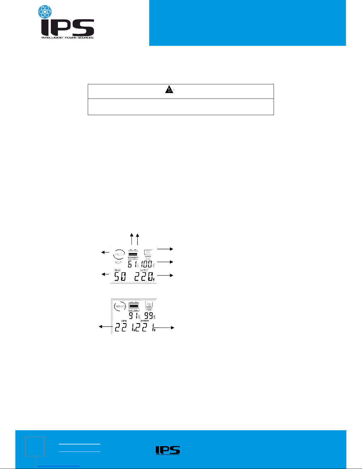
4.2 Display interface
Inverter mode
Mains power mode
4.3 Settings
4.3.1 Setting operation
In normal mode, press and hold “ON” + “OFF” button at the same time for 3 seconds to go to Setup mode.
In Setup mode, press and hold “ON” + “OFF” button at the same time for 3 seconds to exit from Setup mode, and the setting
are not saved.
In Setup mode, press “ON” button for page turning to select configuration options.
In Setup mode, press “OFF” button to configure current settings.
In Setup mode, press “ON” button to turn to page “Save & Exit” interface, press “OFF” button and select “Y”, then press “ON”
button to confirm to save datas and exsit from Setup mode.
After the setting is configured, shut down and restart the inverter before the settings takes effect.
Load
Battery capacity
Inverter output voltage
Fan swing
Inverter output frequency
Input voltage
Output voltage
Load
Page 11

IPS home inverter manual
www.ips-ups.eu 4.09.2017
info@ips-ups.eu IPS-home-inverter-manual_ENG-R1
11
In normal mode and starting state, press “OFF” button to mute.
If there is failure and failure is solved, press “OFF” button first and release it to press “ON” button, and restart the inverter for
normal use.
4.3.2 General settings
Configure these settings at any time, using the display interface.
No.
Parameters
Default
Value
Options
LCD display
1
OUT: Rated output voltage of the
inverter (option)
230V
220V / 230V
/ 240V
2
INP: Input power matching of the
generator (option)
120%
10% ~ 120%
(based on
rated power)
3
HZ: Rated output frequency of the
inverter (option)
50HZ
50HZ / 60HZ
4
RANG: Input frequency range
setting
(option)
± 5%
± 5% ~ ±
15%
5
B: Equalizing charge voltage
(option)
14.1V
13.6V ~
15.0V
6
F: Floating charge voltage (option)
13.5V
13.2V~14.6V
7
A: Battery low voltage alarm point
setting (option)
10.8V
9.6V ~ 13.0V
8
E: End of discharge voltage
(option)
10.2V
9.6V ~ 11.5V
9
CUR: Charging current (option)
10A
(300W )
20A
(600W
~3500W)
0 ~ 60A
10
IECO: Inverter no-load ECO mode
Note: If select “Y”, check whether the
configured load rate in “ Inverter
shutdown load rate” is correct or not,
if not, change it. (option)
N
Y / N
Page 12
IPS home inverter manual
www.ips-ups.eu 4.09.2017
info@ips-ups.eu IPS-home-inverter-manual_ENG-R1
12
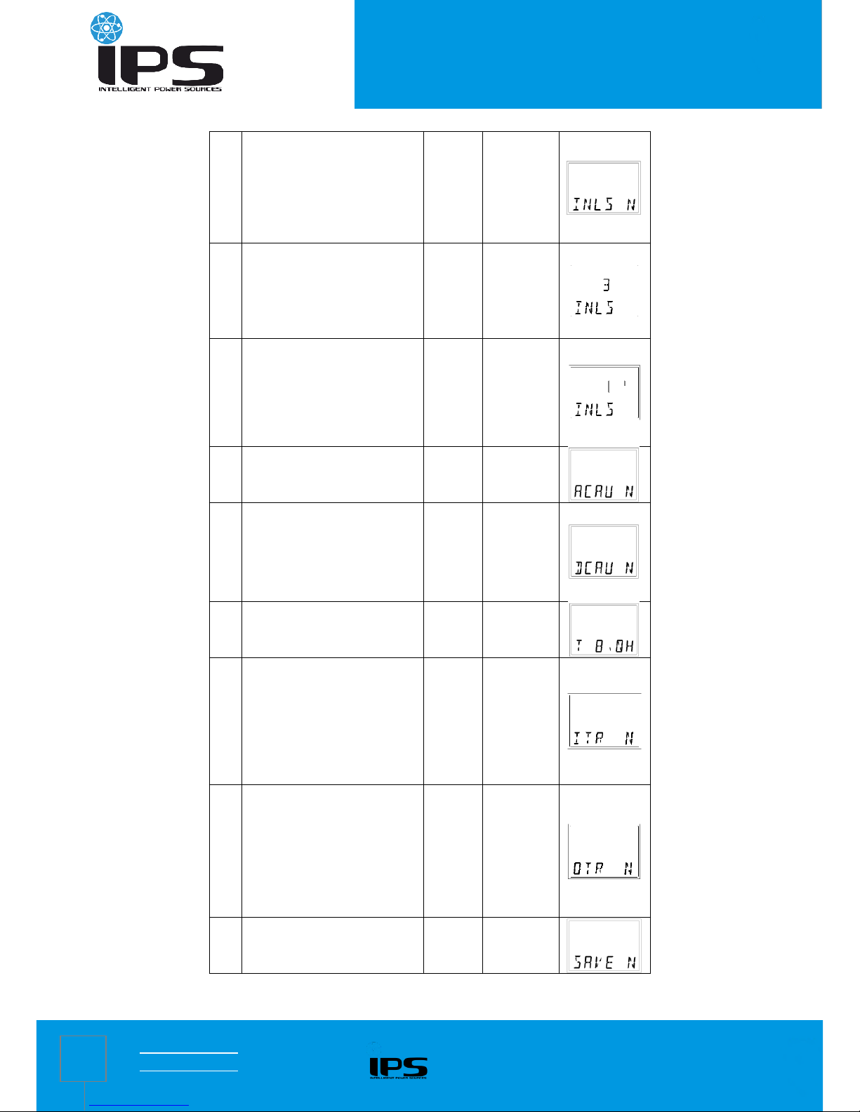
11
INLS: Inverter no-load shutdown
function
Note: If select “Y”, check whether the
configured load rate in “ Inverter
shutdown load rate” is correct or not,
if not, change it. (option)
N
Y / N
12
INLS: Setting of the load rate of UPS
auto-shutdown, The load rate of
shutdown needed on the scene shall
prevail during application. (Shall be taken
as valid only when DC supply power)
(option)
3 %
3 % ~ 50 %
13
INLS: Setting of the delay time of
UPS auto-shutdown, When load ≤
setting value, the system will shut
down after the configured time.
(Shall be taken as valid only in
battery mode) (option)
1 min
1 ~ 99 min
14
ACAU: AC self-starting function
(option)
Y
Y / N
15
DCAU: DC auto restart function
Note: If select “Y”, check whether
the configured time in “DC auto
restart time” is correct or not, if not,
change it. (option)
N
Y / N
16
T: DC auto restart time (option)
1H
0.5H ~ 8.0H
17
ITR: Input voltage display setting ,
displays the current rated voltage of
the system; If select “100 /…/ 240”,
the input voltage displays “100V /…/
240V”, the transformer variable is the
configured voltage value: rated
voltage value. (option)
OFF
200 - 240V
UPS: OFF /
100 / 110 /
115 / 120;
100 - 120V
UPS: OFF /
200 / 220 /
230 / 240
18
OTR: Output voltage display setting,
displays the current rated voltage of
the system; If select “100 /…/ 240”,
the output voltage displays “100
V/…/240 V”, the transformer variable
is the configured voltage value: rated
voltage value. (option)
OFF
200 - 240V
UPS: OFF /
100 / 110 /
115 / 120;
100 - 120V
UPS: OFF /
200 / 220 /
230 / 240
19
SAVE: Save and Exit
Y / N
Page 13
IPS home inverter manual
www.ips-ups.eu 4.09.2017
info@ips-ups.eu IPS-home-inverter-manual_ENG-R1
13
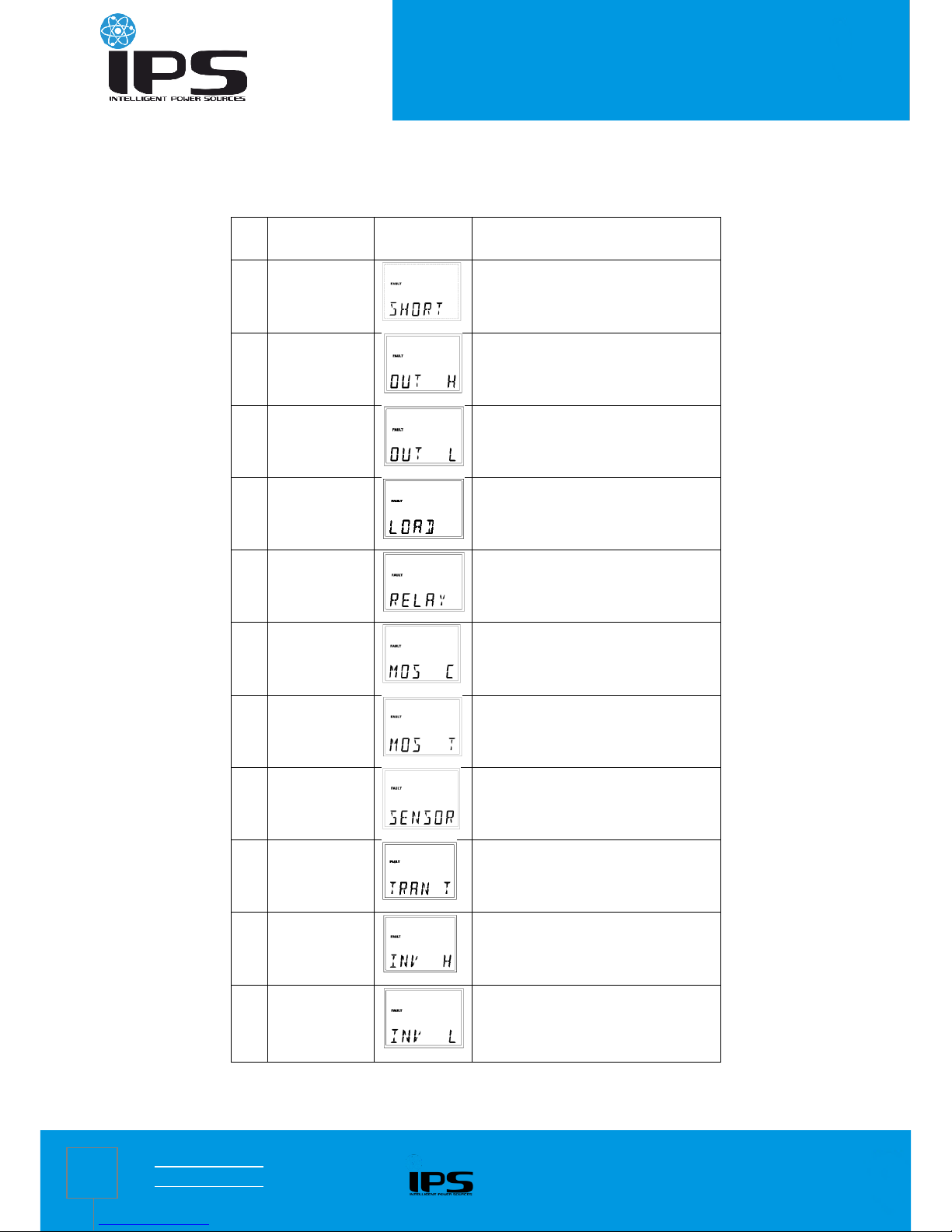
4.4 Troubleshooting
This section lists the status and alarm messages that the UPS might display. A suggested corrective action is listed with each
display message to help you troubleshoot problems.
No.
Problem
Description
Display
Message
Corrective Action
1
AC output short
circuit
Check if the load is short circuited.
2
AC output
voltage is too
high
Contact the dealer or supplier from whom it
was purchased.
3
AC output
voltage is too low
Contact the dealer or supplier from whom it
was purchased.
4
Output overload
Check the load.
5
Relay fault
Contact the dealer or supplier from whom it
was purchased.
6
MOSFET overcurrent
Contact the dealer or supplier from whom it
was purchased.
7
MOS
overtemperature
Decrease the operating load. Contact the
dealer or supplier if the problem persists.
8
Connection of
heat sink and
temperature
sensor abnormal
Contact the dealer or supplier from whom it
was purchased.
9
Transformer
overtemperature
Decrease the operating load. Contact the
dealer or supplier if the problem persists.
10
Inverter AC
output voltage is
too high
Contact the dealer or supplier from whom it
was purchased.
11
Inverter AC
output voltage is
too low
Contact the dealer or supplier from whom it
was purchased.
Page 14

IPS home inverter manual
www.ips-ups.eu 4.09.2017
info@ips-ups.eu IPS-home-inverter-manual_ENG-R1
14
12
Soft-start fault
Contact the dealer or supplier from whom it
was purchased.
13
BUS voltage is
too high (Battery
is overchargered
)
Check the battery voltage. Contact the
dealer or supplier if the problem persists.
14
Charging overcurrent
Contact the dealer or supplier from whom it
was purchased.
15
Battery voltage is
too high
Check the battery voltage.
16
Battery overdischarge
protection
Check the battery voltage
17
Fault self-locking
Wait for auto clearance or manually shut
down and restart the inverter
18
CT fault
Check the CT signal line
IPS-UPS
Ul. Mikołowska 39
44-200 Rybnik, Poland
 Loading...