

Page 1

Brief Instruction Manual
for EggBell
29/July/2015
Page 2
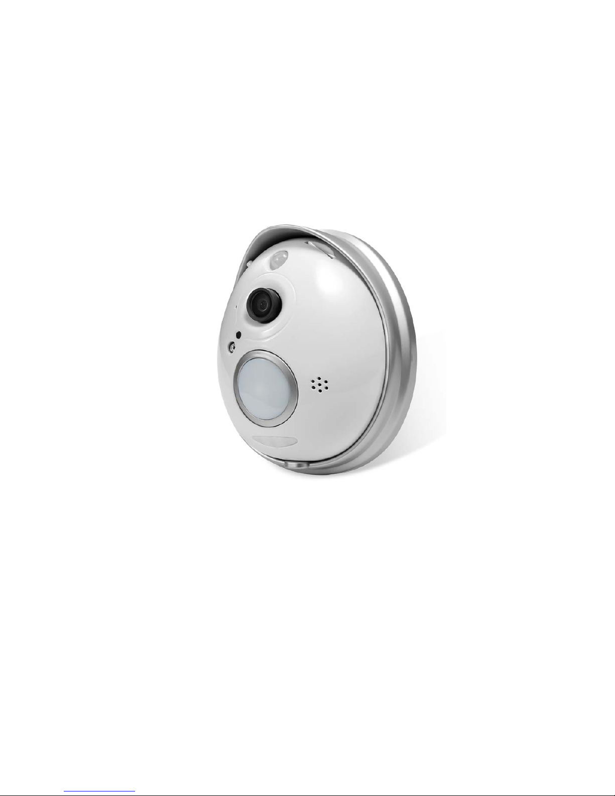
1. Product Introduction & Description
1.1 Brief introduction
Accessories:
----EggBell 1 pcs
----Power adapter 1 pcs
----CD with software 1 pcs
----Instruction Manual 1 pcs
----Installation Package 1 pcs
----Bracket 1 pcs
1.2 Product descript ion
Page 3
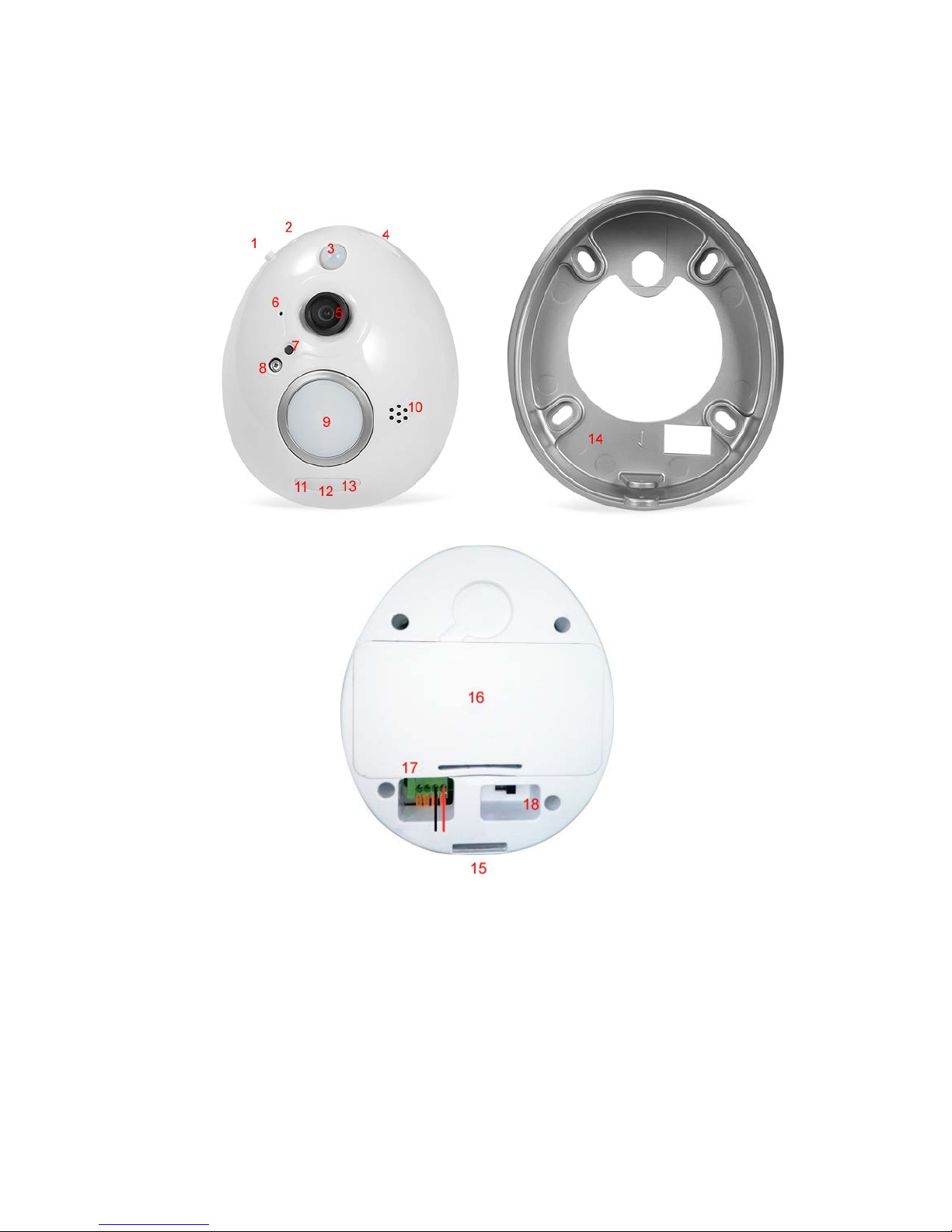
1 WPS 9 Bell Button
2 Reset 10 Speaker
3 PIR 11 Indicator LED for video Recording
4 SD slot 12 Indicator LED for Power
5 Camera Lens 13 Indicator LED for Wifi
6 Microphone 14 Waterproof Case
7 IR cut 15 Anti-tamper screw hole
8 IR LED 16 battery compartment
Page 4

(18650 batteries, brand such as UltraFire)
17 Power port 18 Power switch
Note
:Whe n Egg Be ll is s witc he d on, t he def aul t mo de is ”Smart li nk” mo de ; Pre s s onc e the
“WPS” key, it will enter into WPS mode, Press the “WPS” ke y co ntinuo usly for 5 seconds, it
will enter into AP mode.
2. Installation
2.1 Installation of EggBell
A Installation to replace the peep-hole on the door
1、 Remove the peep-hole
Remove the peep-hole from the door, and get the powe r cord through t he ho le,
just like the picture below:
2、 Connection of the power supply
F ix the smal l ro d on t he b r ac k et with t he hex a gonal sc r ew t i g h ten,get the power cord through
the rod; Connect the power cord into the power port, just like the picture below:
Page 5

Warning: Please use the standard AC adapter for the product,
3、Fix the Bracket
Screw on the four corners of the bracket fixed on the door with the accessories in the installation
package, and tighten the special anti-tamper screw on the bottom, plug in power source.
B Installation on the wall
Page 6

1 Drill the screw holes of wh ich the location i s matched with the f our holes of the bracket, fix
the bracket on the wall with four screws;
2 Get the power cord connected with the power port through the h ole on the back of the
bracket
2.2 Connection with mobile de vice
1. Download and install the P2P application”EggBell”
2. Search the Application ”EggBell” on application store , and download it on your phone (Android
use rs ca n ge t it fro m “Android Market”,or find and install the APP from the CD attac hed; iOS users
can download on App Store)。
3. Install the the application on your mobile phone and then run it, configure the Wifi of the device
under S mart Link mode (e nter ing into S mart Link mode b y default when EggBe ll is switc hed on).
Click the “Configure Device” — “Smart Mode” — Enter in the UID of EggBell UID
( Or scan the QR code to add the device)— Configuration WiFi
Page 7

Note: During the process when configuring Wifi, the blue indicator LED on the right side will
flash frequently; After connected to Wifi, the bule LED will keep always on (like the picture
abo v e), w hi le the re wil l be prom pt tone “ding-dong” from the device to tell you configuring
successfully.
3、After WiFi Configuration, Click “Direct access” —Add Device—Add a networked
device.
Three ways to add device, all of them can add EggBell successsfully
Page 8

Add automatically: Click “search in the LAN”, the UID of EggBell will be
automatically searched, then click Add.
Scan mode: Click the button to scan the QR code on EggBell, the red line need to be
aligned with
the QR code scanner, when hear a "beep", it tells scanning successfully, the scanner will
automatically put the serial number scanned in UID blank. Then enter in the User Name and Password
(They are both “admin” by default). Click the “Edit” on the top right corner, the device will
appear on the device list.
Page 9

Manually:Click the "Add" icon, ma nually e nter t he seria l number UID( UID serial number at
the bottom of the label on E g gBe l l, mix ed w it h letters and numbers).
Then enter in the User Name and
Password (They are both “admin” by default). Click the “Ed it” on the top right corner, the device
will appear on the device list.
4. The door bell will appear on the device list when added successfully. When click the “Edit” on the
top right corner, you ca n also reset the de vice na me, the user na me, the pas sword, a nd de le te the
device from the list, etc.
Page 10

3.Function Introduction
3.1Push Function
After the door bell added s uccessfully, admit ”Outdoor call-in”, the push function
will be available.
Page 11

3.1.1 Push n otification when press t he bell button
When someone press the bell button, EggBell will start recording the video automatically for 20
seconds, and storing the video file in the TF card, at the same time it will push the mess age to the
APP on your phone with ringing tone. You could click to accept the call, then ente r into the monitor
image to reach the function s uch as snapshot, record vide o, talk with the visitor, etc. Jus t like the
picture below:
3.1.2 Push n otification for staying
When someone keep s taying in front of EggBell for 20-30 seconds,EggBell will start recording the
video automatically for 20 seconds, and storing the video file in the TF card, at the same time it will
push the message to the A PP on your phone with ring ing tone. You c ould click to accept the call,
then ente r into the monitor image to reach the function such as snapshot, record video, talk with
the visitor, etc. Just like the picture above.
3.2 Access to the files of record ing and snapshot
3.2.1 Acce ss to t he local files on the phon e for r ecording and snapshot
The files for snapshot manually and recording are stored locally on mobile phone,you can access to
them, and check the call logs on APP, just like the picture below:
Page 12

3.2.2 Acce ss to t he fi les save d in th e TF card fo r reco rding a nd snapshot
The files of snapshot and reco rding via Pres s ing button and Staying overti me are stored in the TF
card, you can access remotely to these files on APP, just like the files below:
Page 13

This device complies with Part 15 of the FCC Rules. Operation is
subject to the following two conditions: (1) this device may not
cause harmful interference, and (2) this device must accept any
interference received, including interference that may cause
undesired operation.
The sta tements should be displa yed in the u ser manual:
Changes or modifications not expressly approved by the party responsible for compliance could void the
user’s auth ority to operat e the equipm ent.
This equi pment has been tested and found to comply with the limits for a Class B digital device, pursuant to
Part 15 of the FCC Rules. These limits are designed to provide reasonable protection against harmful
interference in a resi dential installation. This equipmen t gen erates, uses and can radi ate radio frequency
energy and, if not installed and used in accordance with the instructions, may cause harmful interference to
radio communications. However, there is no guarantee that interference will not occ ur in a parti cular
installation.
If t his equipmen t does c ause harmful interf erence to radio or television reception, which can be det ermine d
by tur nin g th e equipm e nt off and o n, th e user i s enc our ag ed to tr y to cor r ec t th e i n ter fer en c e b y o n e or m ore
of the following measures:
-- Reorient or relocat e the recei ving ant enna.
-- I ncreas e the separati on between t he e quipment and recei ver.
-- Connect t he equipm ent into an outlet on a c ircuit different from th at to which the receiv er is connected.
-- Consul t the dealer or an experi enced radio/T V technician for help.
This equipment must be installed and operated in accordance with provided instructions and the antenna(s)
used for this transmitter must be installed to provide a separation distance of at least 20 cm from all
persons and must not be co-located or operating in conjunction with any other antenna or transmitter. Endusers and installers must be provided with antenna installation instructions and transmitter operating
conditions for satisfying RF exposure compliance.
 Loading...