

Page 1

Better Pack® 555e Series
Model 555eS & 555eSA
Electronic Tape Dispenser
BP555e Series OPERATING MANUAL
BP P/N: MAN-555e-OPR File Name: BP555e-OPERATING MANUAL-26May15.doc
Page 2

Better Packages
Safety Notice
This manual is a non-controlled document.
This manual has been carefully compiled and checked for accuracy. Information in this manual does not constitute a
warranty of performance. Furthermore, Better Packages reserves the right to revise this publication and make changes
from time to time, in its content.
Better Packages ASSUMES NO LIABILITY WHATSOEVER FOR ANY LOSSES OR DAMAGES INCURRED AS A
RESULT OF INFORMATION CONTAINED IN THIS MANUAL.
Proprietary Notice
This publication contains information proprietary and confidential to Better Packages. Any reproduction, disclosure, or
use of this publication is expressly prohibited except as Better Packages may otherwise authorize in writing.
IPS Packaging
110 Jack Casey Ct
Fountain Inn, SC 29644
Phone: 800-277-7007
Web: www.ipack.com
CAUTION: If an object falls into one of the cover guide arm slots, disconnect power and notify service personnel.
CAUTION: Metal surfaces of the heater may attain temperatures up to 74 degrees Celsius (165 degrees Fahrenheit).
CAUTION: This equipment generates, uses, and can radiate radio energy and, if not installed and used in
accordance with the instruction manual, may cause interference to radio communications. It has been tested and
found to comply with the limits for Class A computing device pursuant to Subpart J of Part 15 of FCC Rules, which
are designed to provide reasonable protection against such interference when operated in a commercial
environment. Operation of this equipment in a residential area is likely to cause interference, in which case the user,
at his own expense, will be required to take whatever measures may be required to correct the interference.
CAUTION: When moving the tape dispenser from one location to another, power must be disconnected and the
water bottle, water tank and brushes should be removed to prevent spillage that could result in an electrical shock
hazard.
NOTE: Power must be removed before attempting to clear a tape jam.
NOTE: The top cover is interlocked such that the unit will not operate if the cover is not fully closed.
2
Page 3

Better Packages
Table of Contents
Section 1 - Unpacking and Setup
Unpacking ................................................................................................................................... 5
Checking the Contents ................................................................................................................ 5
Fill Out the Warranty Card .......................................................................................................... 5
Adjusting the Roll Guides ............................................................................................................ 5
Loading the Tape ........................................................................................................................ 6
Checking Upper Tape Plate ........................................................................................................ 7
Installing the Bottle and Water Tank ............................................................................................ 8
Mount the Dispenser to the Work Bench (Optional) ...
Attach the Power Cord .............................................................................................................. 10
Section 2 -Detailed Operation
Turn the System “ON” ............................................................................................................... 12
Adjust the Setting on The Heater Assembly. ............................................................................. 12
Select the Tape Length (Standard Model) ................................................................................. 13
Select the Tape Length (Automatic Model) ............................................................................... 14
To Dispense a Random Length of Tape .................................................................................... 14
To Dispense a Length of Tape Equal to a Number Button Length ............................................. 15
To Dispense a Specific Length Not on a Number Button ...........................................................15
To Dispense Tape Longer Than the Amount on a Number Button ........................................... 15
To Dispense Tape Shorter Than the Amount on a Number Button........................................... 15
To Dispense a Length of Tape Twice the Length of a Number Button ...................................... 16
To Adjust the Length of a Number Button and Then Double It ................................................. 16
To Repeat the Length Previously Dispensed (Standard Model) ............................................... 17
To Repeat the Length Previously Dispensed (Automatic Model) ............................................... 17
To Activate Automatic Mode ..................................................................................................... 18
To Repeat One Tape Length Automatically ............................................................................... 18
To Repeat Two Tape Lengths Automatically ............................................................................. 18
To Repeat Three Tape Lengths Automatically .........
...............................................................10
................................................................. 19
Section 3 - Sealing with Gummed Tape
Choosing the Best Tape for Your Application ............................................................................ 20
Advantages of Water-Activated Tape ........................................................................................20
Identifying the Types of Tape .................................................................................................... 20
What You Should Know About Adhesive Formulas ................................................................... 21
The Different Grades (Weights) of Sealing Tape ....................................................................... 21
Selecting Tape .......................................................................................................................... 21
Proper Tape Moistening ............................................................................................................ 22
Adjusting the Amount of Water Applied to the Tape ..................................................................22
Setting Heater Controls ............................................................................................................. 22
Choosing the Correct Tape Length ........................................................................................... 23
Applying Tape to the Carton ...................................................................................................... 23
3
Page 4

Better Packages
Table of Contents
Section 4 – Maintenance
Washing the Tank, Brushes, and Bottle .................................................................................... 24
Cleaning the Shear Blades ....................................................................................................... 25
Suggested Preventative Maintenance Schedule ....................................................................... 25
Clearing Jams ........................................................................................................................... 26
Changing the Fuse .................................................................................................................... 27
Lubrication ................................................................................................................................ 28
Cleaning.................................................................................................................................... 29
Section 5 – Specifications
Model Descriptions ................................................................................................................... 30
Technical Specifications ............................................................................................................ 30
Port Connectivity ....................................................................................................................... 30
Connector Configurations……………………………………………………………...………………30
Model Types………………………………...…………………………………………...………………31
Section 6 -Service and Warranty
This section provides warranty information and how to obtain service.
Limited Warranty Statement ......................................................... Error! Bookmark not defined.
Error! Reference source not found.Error! Reference source not found.Error! Bookmark not defined.
Index ......................................................................................................................................... 33
4
Page 5
Better Packages Section 1
B
rush
Upper
Operating
Unpacking and Setup
UNPACKING
When you open the top flaps on the box for the tape dispenser, there will be instructions for removing the
tape dispenser from its packaging. Save the box and packing materials in case you need to ship the unit
at some future time.
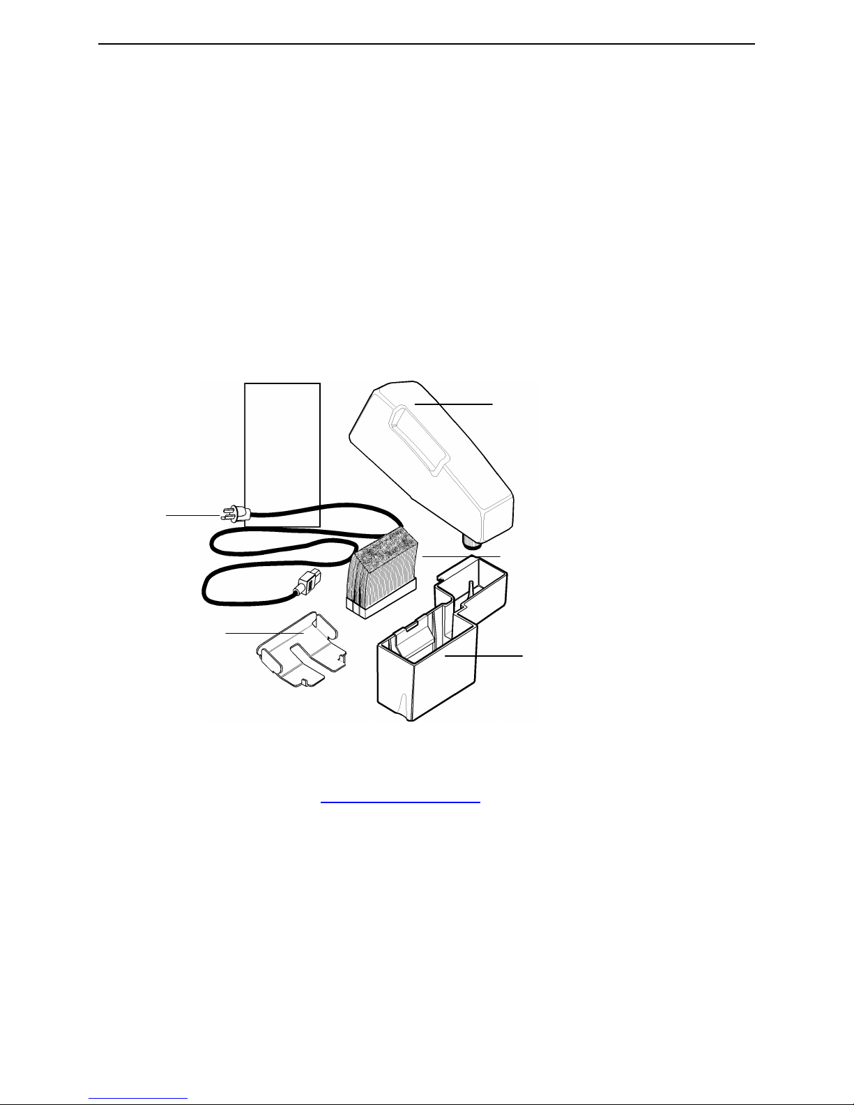
CHECKING THE CONTENTS
Packaged inside the tape dispenser, under the top cover are the following items: See Figure 1.
• Brush Assembly (three beveled brushes assembled together)
• Water Tank (a black plastic piece with a metal bracket attached to it)
• Water Bottle (a white plastic bottle with a screw cap)
• Upper Tape Plate
• Power Cord
• Operating Guide
• Warranty Card (inside the Operating Guide)
• 2 Tape Roll Guides (not pictured, see page 6)
Power Cord
FIGURE 1 - Checking Package Contents
Tape
Plate
Guide
Water Bottle
Assembly
Water Tank
FILL OUT THE WARRANTY CARD
Filling out the warranty card and returning it to us protects your warranty and allows us to keep you
informed of product upgrades. Visit www.betterpackages.com to fill out the warranty card online.
Preparing the Unit for Operation
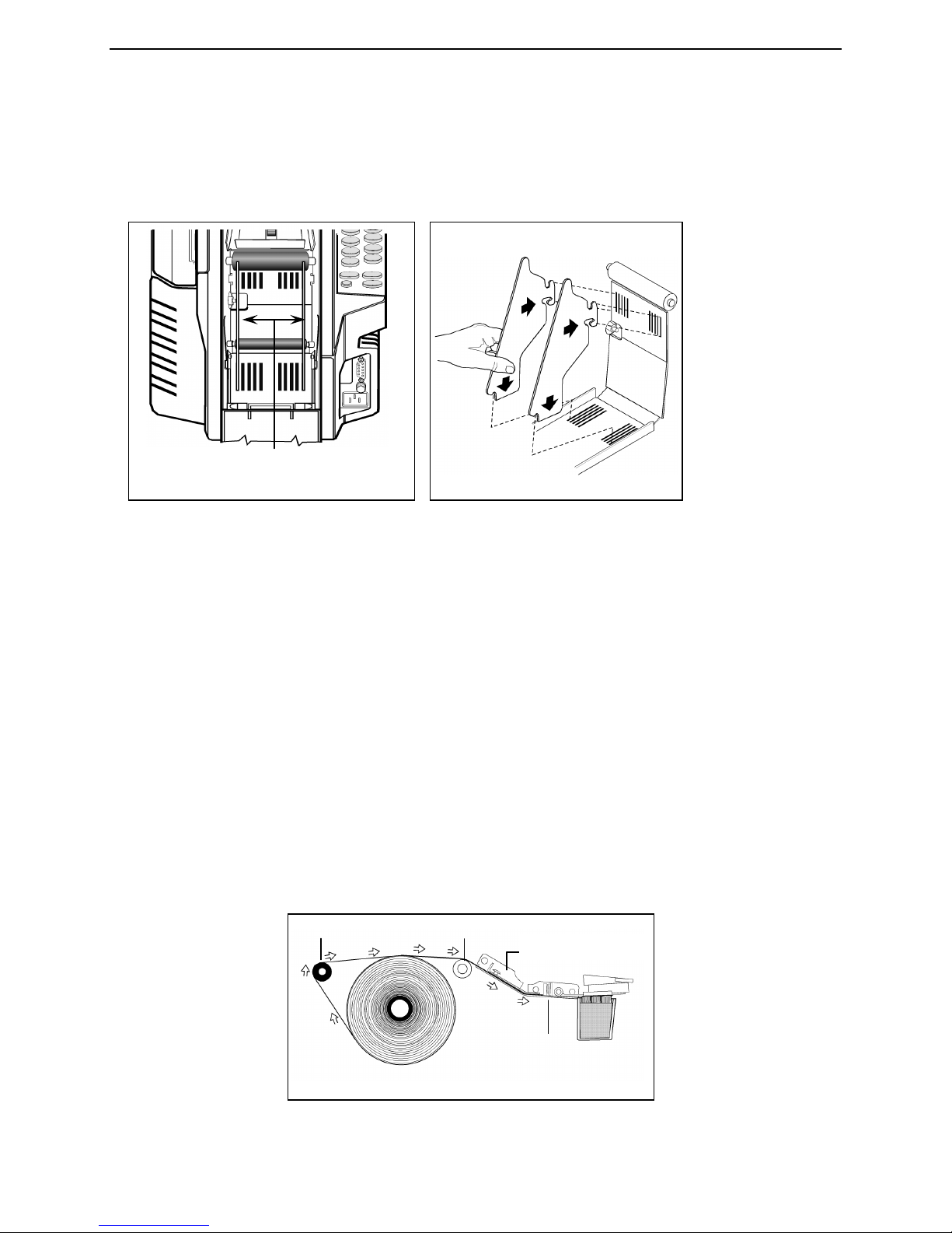
ADJUSTING THE ROLL GUIDES
Roll guides fit into slots in the front and bottom panels of the tape basket. They hold the tape roll vertical
to allow the tape to unwind. You must adjust these guides for the size of the tape being used.
NOTE: This machine can dispense tapes from 1-½” to 3.0” wide.
5
Page 6
Better Packages Section 1
FIGURE
2 - Removing the Guides from the Slots
Insert all four tabs the same number of
ROLL GUIDES
Lift Roller
Black
Roller
Shear
FIGURE
4 -
Loading the Tape Roll
Unpacking and Setup
Procedure:
1. Remove a guide from its current position by grasping the guide, lifting it up and pulling the bottom of it
to the rear of the unit. See Figure 2.
2. Reinsert each guide pressing it first into the front slot and then into the bottom slot. See Figure 3.
• Set the space between the guides to just larger than the width of the tape.
• Use the guides to center the tape as much as possible by inserting each guide into a slot the same
distance from the outside edge of the panel. For example, if you set the bottom part of the guide in the
second slot from the outside edge of the panel, set the front part of the guide also into the second slot from
the outside edge.
LOADING THE TAPE
1. Cut the end of the tape so that it has a clean, square end to feed under the
drive wheel.
2. Load the tape roll into the basket so that:
• The adhesive side is down.
• The roll is upright between the roll guides. See Figure 4.
• The end of the tape goes over the:
- Top of the tape roll from back to front.
- Lift Roller then rubber Roller
• The end of the tape is fed under the top tape plate and drive wheel; and is
butted against the shear blade.
3. Close the top cover.
Feed the tape:
• Adhesive side down
• Around the lift roller
• Over the black roller
• Under the upper tape plate
• Under the guide bar
• Up against the shear blade
slots from the outside edge.
FIGURE 3
Upper Tape Plate
Blade
6
Page 7

Better Packages Section 1
The Upper tape plate must fit:
Drive Wheel
FIGURE
6 -
Upper Tape Plate in
Drive Wh
eel
Guide
FIGURE
7 –
Positioning
the Upper
Tape Plate
Upper
Unpacking and Setup
CHECKING UPPER TAPE PLATE
Make sure the upper tape plate is in its proper position as shown in Figure 6. If the plate is not correctly
positioned:
1. Hold the upper tape plate by its rear edge, See Figure 7, and guide it forward so that the front slot
centers around the drive wheel.
2. When the cutouts in the sides of the plate are above the retaining buttons, drop the plate down and
slide it forward as far as it will go.
Proper Position
- Around the drive wheel
- Under the guide bar
- Over the rubber roller Drive Wheel
Bar
NOTE: There is a round guide bar just before the cutting blade. The front of the upper tape plate should
be under that guide bar.
Tape
Plate
7
Page 8
Better Packages Section 1
Br
ushes must be angled toward the
FIGURE
8 -
Inserting the Brush
Retaining bracket
Unpacking and Setup
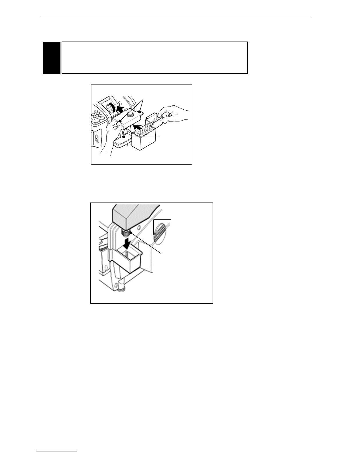
INSTALLING THE BOTTLE AND WATER TANK
1. Insert the brush assembly in the water tank. The brush assembly must be tilted toward the dispenser
so that the cotter pin will clear the retaining bracket as it is pressed into place. See Figure 8. Then rotate
the brush forward so that it seats flatly on the bottom of the water tank. The edge of the base of the brush
should be under the retaining bracket.
2. Lift the front of the heater assembly and slide the water tank into position at the front of the dispenser.
front of the dispenser in order to work.
Installing the brushes backwards will
cause a troublesome tape jam.
At first, tilt the brush toward the dispenser so that the head of the cotter pin clears the retaining bracket as
you push the brushes into the tank. Then tilt the brush back so that it seals flatly on the bottom of the
tank.
The bottom of the water tank should be even with the edges of the shelf it sits on and the water tank will
drop slightly into the shelf when it is correctly positioned.
3. Lower the heater assembly.
4. Fill the bottle with water.
into the Water Tank
8
Page 9
Better Packages Section 1
!
FIGURE
9 -
Handling the Heater Assembly
The tank will
positioned
Use these tabs to raise
FIGURE
10 -
Attaching the
Bottle
f
its in this area
Center of the
in the tank
Unpacking and Setup
CAUTION: Under normal operating conditions, the bottom of the
heater assembly may be HOT. Handle the assembly ONLY by the
tabs sticking out from the sides. See Figure 9.
and lower the heater
assembly
drop slightly
into this
shelf when it
is correctly
5. Position the bottle onto the right side of the dispenser. The spring-loaded center of the bottle’s cap
must be on the pylon protruding up from the water tank. See Figure 10.
bottle cap fits
over the pylon
Bottle to the Dispenser
normally
9
Page 10
Better Packages Section 1
FIGURE
11 -
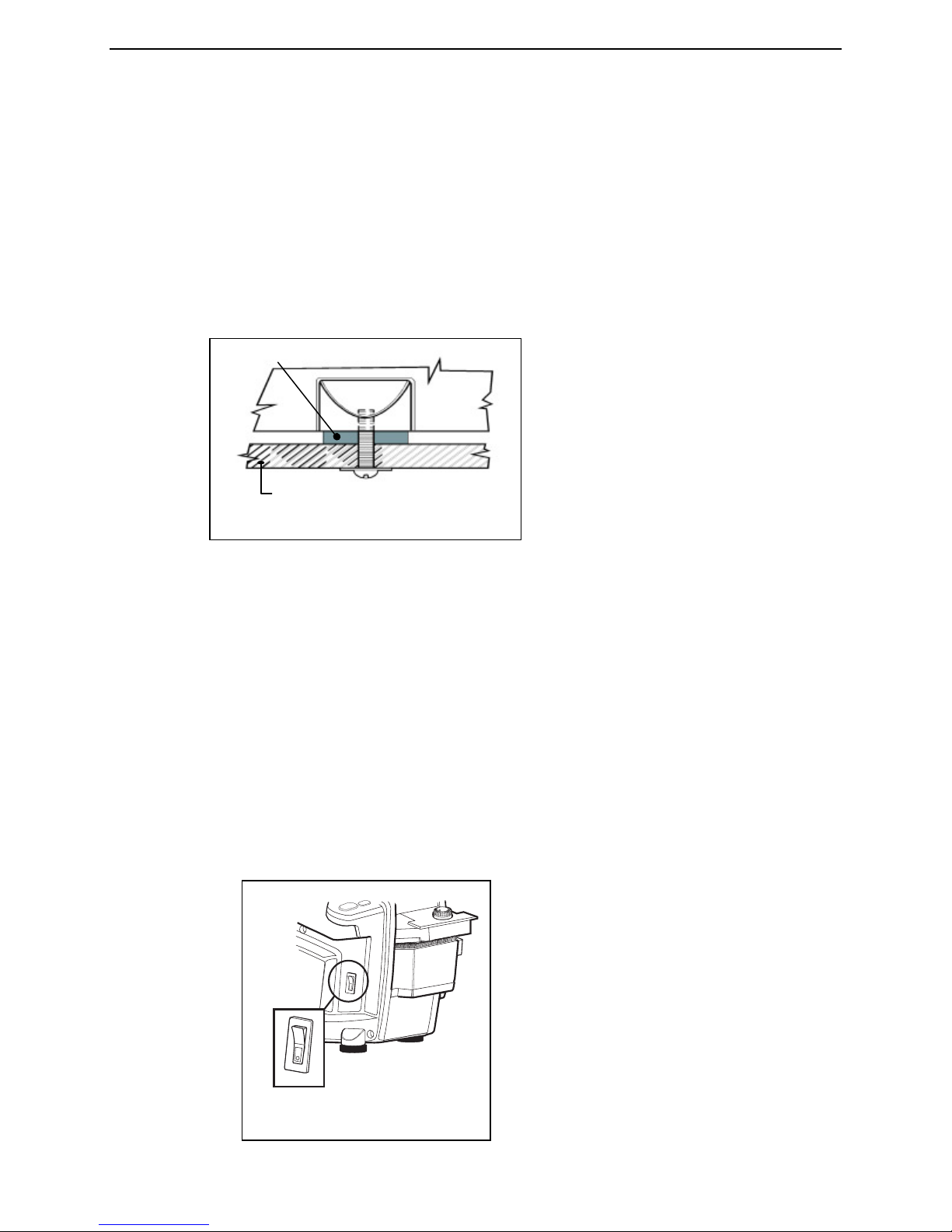
Mounting the Dispenser to a Bench Top
Use the feet supplied with the dispenser.
Top of bench or table.
FIGURE
12 –
Power Switch Location
Unpacking and Setup
MOUNT THE DISPENSER TO THE WORK BENCH (OPTIONAL)
The dispenser may be bolted to the work bench or table that it sits on. The main reason to do this is the
dispenser can’t be knocked off the bench-top should someone bump into it. The dispenser is shipped with
four (4) rubber feet attached to the bottom panel by 10-24 Phillips head screws.
1. Drill four holes into the top of the bench.
2. Remove the screws and washers from the bottom panel that hold the feet
in place.
3. Measure the thickness of the bench top. Obtain 4 (four) 10-24 screws/bolts that are 9/16” to 1-1/16”
longer than the thickness of the bench top. For example, if the bench top is 1” thick, use screws 1-9/16” to
2-1/16” long to attach the dispenser to the bench top.
4. Position the dispenser over the bench so that their mounting holes are lined up.
IMPORTANT:
dispenser and the bench from vibration from the dispenser’s normal operation.
5. Insert the 10-24 screws through the bottom of the bench, through the rubber feet, into the threaded
holes in the bottom panel. See Figure 11.
• Use Loctite® or a similar thread locking compound on the threads of the screws to prevent them from
loosening.
• Tighten the screws until they are snug, but do not tighten them so much that the rubber feet are
compressed.
• Use washers under the heads of the bolts or screws used to secure the dispenser to the bench top.
ATTACH THE POWER CORD
1. Ensure that the power switch is in the OFF (down) position. See Figure 12.
2. Attach the female end of the power cord to the dispenser connector.
See Figure 13.
Keep the feet between the dispenser and the bench top. This will protect both the
10
Page 11

Better Packages Section 1
FIGURE
13 –
The Electrical Panel
Use this
Fuse
Attach
wire grounded type
Unpacking and Setup
There are two other components on the electrical panel:
• The 9-Pin female connector that can be used:
On Standard and Automatic models to attach a pedal switch. On Automatic models (only) to access an
RS-232 serial data port. Using this data port, the Better Packages Automatic Measuring Device (AMD-1)
(purchased separately) can be utilized to instantly measure & dispense the exact length as tape needed.
• A user-replaceable fuse.
See the Maintenance Section
3. Plug the male end of the power cord into a 110/120v 60hz receptacle.
port for
optional
pedal
control
or AMD-1
Holder
the A/C
Power
Cord
here
If you are not sure if the electrical system in your building is properly grounded, contact a licensed
electrician.
WARNING: FOR YOUR SAFETY
All metal parts of this machine are
electrically grounded through a
3-wire power supply. You must plug
this cord into a 3receptacle.
11
Page 12

Better Packages Section 2
FIGURE
14 -
On/Off Switch Location
FIGURE
15 -
Handling the Heater Assembly
Temperature Adjustment Control Knob
!
TURN THE SYSTEM “ON”
Turn the power switch to the “ON” (up) position. The switch will light and the dispenser will “beep” once.
See Figure 14.
Operation
ADJUST THE SETTING ON THE HEATER ASSEMBLY
Finding the correct setting for the tape you are using is a matter of simple testing. Turn adjustment knob
to highest setting (clockwise), then back off slightly to the lowest temperature setting that best meets your
needs. See Figure 15. Refer to Section 3 “Sealing with Gummed Tape”.
When the heat is properly adjusted, the tape will adhere quickly to the parcel. Too low a setting may
result in the tape taking slightly longer to properly adhere.
CAUTION: The bottom of the heater assembly gets HOT!
Handle the heater only by the tabs protruding from the sides
of its top. See Figure 15.
12
Page 13

Better Packages Section 2
X 2
+
-
45
39
42
36
30
24
27
33
21
15
9
6
12
18
REPEAT
START
555
e S
Better Pack
FIGURE
16a -
Keypad for Tape Length Selection
PLUS Button
MINUS Button
REPEAT START
Button
Manual F
eed Button
tape while pressed. Length (4” to
Number Buttons
SELECT THE TAPE LENGTH (STANDARD MODEL)
Pressing a button or combination of buttons allows you to dispense tape in lengths from 4” to a maximum
of 120” in increments of ½”. See Figure 16a.
to selected length
(1 cm) from selected length
Repeats length selected before
this button was pressed
Adds ½” (1 cm)
Subtracts ½”
X2 Button Doubles selected length
of tape
120”) is determined by how long
the button is held
Select length
Dispenses
Operation
13
Page 14

Better Packages Section 2
X 2
A
+
-
45
39
42
36
30
24
27
33
21
15
9
6
12
18
REPEAT
START
REPEAT 2
ENTER
555
e S A
Better Pack
FIGURE
16b -
Keypad for Tape Length Selection
PLUS Button
MINUS Button
REPEAT START
Button
A Button
Automatic mode (light will be “on”
when unit is in automatic mode)
Number Buttons
Manual Feed Button
e pressed. Length (4” to
REPEAT 2
ENTER Button
The Manual Feed Button
Operation
SELECT THE TAPE LENGTH (AUTOMATIC MODEL)
Pressing a button or combination of buttons allows you to dispense tape in lengths from 4” to a
maximum of 120” in increments of ½”.
See Figure 16b.
to selected length
(1 cm) from selected length
Repeats length selected before
this button was pressed
Adds ½” (1 cm)
Subtracts ½”
X2 Button Doubles selected length
of tape
tape whil
120”) is determined by how long
the button is held
Used for a 2nd length or preset
length.
Press to place the unit in
Select length
Dispenses
TO DISPENSE A RANDOM LENGTH OF TAPE:
Press and hold the manual feed button (down arrow) until the desired length of tape is dispensed.
It will dispense a length of 4” (10 cm) to a maximum of 120” (305 cm) depending upon how long the
button is held down.
(lower right on the keypad)
14
Page 15

Better Packages Section 2
Operation
TO DISPENSE A LENGTH OF TAPE EQUAL TO A NUMBER BUTTON LENGTH:
Press To dispense 42”
Press To dispense 15”
TO DISPENSE A SPECIFIC LENGTH NOT ON A NUMBER BUTTON:
• You can add or subtract ½” increments from any number button length.
• You can double any button number length.
• You can adjust a number button length (longer or shorter) and then double it.
• You can repeat the length previously dispensed with a single button.
ERROR NOTIFICATION
NOTE: If you press a combination of keys that doesn’t work, the system lets you know by beeping three
times. If this happens, re-enter the key or combination of keys to produce the length or lengths that you
require.
TO DISPENSE TAPE LONGER THAN THE AMOUNT ON A NUMBER BUTTON:
Press To dispense 42-½”
(one ½” is added for each press of the button).
In this case it is ½” (1 x ½”).
Press To dispense 43” (one ½” is added for each
press of the button.
In this case it is 1” (2 x ½”).
Press the button once for each ½” you want to add to a number button.
You can press the button as many times as you want before you press the number button. For
example;
• To dispense 42-½” of tape, press the button once (to add ½”) and then
press the button. A 42-½” length of tape is dispensed.
TO DISPENSE TAPE SHORTER THAN THE AMOUNT ON A NUMBER BUTTON:
Press To dispense 41-½”
(one -½” is subtracted for each press of the button).
In this case it is 1/2” (1 x ½”).
Press To dispense 41”
(one ½” is subtracted for each 1” press of the button).
In this case it is 1” (2 x ½”).
15
Page 16

Better Packages Section 2
Press the button once for each ½” you want to subtract from a number button. For example:
• To dispense 42-½” of tape, press the button once (to subtract ½”) and
then press the button. A 41-½” length of tape is dispensed.
• To dispense 41” of tape, press the button twice (to subtract one inch) and
then press the button. A 41” length of tape is dispensed.
• You can press the button as many times as you want before you press the number button.
Operation
TO DISPENSE A LENGTH OF TAPE TWICE THE LENGTH OF A NUMBER BUTTON:
Press To dispense 84”. (2 times 42 = 84)
Press To dispense 54”. (2 times 27 = 54)
First press the button and then press the number button.
For example:
• Pressing and then pressing the button will dispense 84” of tape.
• Pressing and then pressing the button will dispense 54” of tape.
TO ADJUST THE LENGTH OF A NUMBER BUTTON AND THEN DOUBLE IT:
Press To dispense 63”, 30” plus 1½”
(for the three buttons) = 31-½”.
31-½” times 2 (for the button) = 63”.
The button can be used together with the button or the button to double the length of an
adjusted number button. For example;
• If you press the button three times (to add 11/2”), press the button, and then press the
number button, 63” of tape will be dispensed.
16
Page 17

Better Packages Section 2
REPEAT
START
REPEAT
START
REPEAT
START
6
9
Operation
TO REPEAT THE LENGTH PREVIOUSLY DISPENSED (STANDARD MODEL):
The dispenser “remembers” the last length of tape dispensed and stores that value in its memory.
Pressing the REPEAT key dispenses the same length of tape that was previously dispensed. This is
especially handy if you are dispensing a tape length that was adjusted using the or the buttons.
The REPEAT key also repeats standard number button lengths. Each time you dispense a different length
of tape by pressing a different button or combination of buttons, that new figure:
• Is stored in the REPEAT button memory
• Becomes the length dispensed the next time you press the REPEAT button.
The REPEAT Button –
Lower left on the keyboard
TO REPEAT THE LENGTH PREVIOUSLY DISPENSED (AUTOMATIC MODEL):
The dispenser “remembers” the last two length of tape dispensed and stores those values in its memory.
REPEAT 2
ENTER
STANDARD MODE:
To dispense a six inch tape press once. Remove the piece of tape.
Press this will also dispense a six inch tape.
Press and a nine inch piece of tape will be dispensed. Remove the piece of tape.
Press a nine inch piece of tape will again be dispensed.
REPEAT 2
ENTER
17
Page 18

Better Packages Section 2
REPEAT
START
6
9
6
Operation
Remove the piece of tape, press a six inch piece of tape will be dispensed.
In this way, any two lengths can be memorized by the unit's electronics and can be repeated using:
REPEAT
START
REPEAT 2
ENTER
AUTOMATIC MODE:
In the Automatic Mode, removing a piece of tape from the dispenser causes another piece of tape to be
dispensed automatically. Additionally, in the Automatic Mode, the dispenser can remember up to three
tape lengths and automatically dispense them in the order in which they were entered.
TO ACTIVATE AUTOMATIC MODE:
1) Make sure that the last piece of tape dispensed has been removed.
2) Press (A button)
3) The indicator will be illuminated (red).
TO REPEAT ONE TAPE LENGTH AUTOMATICALLY:
Press ... a six inch tape will be dispensed. Remove the six inch tape.
Press
REPEAT 2
ENTER
Press
REPEAT
START
A six inch piece of tape will be dispensed. Remove it and another six inch piece of tape will be dispensed
automatically.
TO REPEAT TWO TAPE LENGTHS AUTOMATICALLY:
First make sure the memory is clear of any lengths previously stored. To do this, press “A”, the indicator
turns off. Remove any piece of tape that may have been dispensed but not removed. Press “A” again.
The indicator lights (red) and the memory is cleared and ready for your input.
Press ... a six inch tape will be dispensed. Remove the six inch tape.
Press
REPEAT 2
ENTER
Press ... a nine inch tape will be dispensed. Remove the nine inch piece of tape.
Press
Press
REPEAT 2
ENTER
REPEAT
START
A six inch piece of tape will be dispensed. Remove the six inch piece of tape and a nine inch piece will
automatically be dispensed. Removing the nine inch piece will then automatically dispense a six inch
piece.
18
Page 19

Better Packages Section 2
6
9
REPEAT
START
12
Operation
TO REPEAT THREE TAPE LENGTHS AUTOMATICALLY:
First make sure the memory is clear of any lengths previously stored. To do this, press “A”, the indicator
turns off. Remove any piece of tape that may have been dispensed and not removed. Press “A” again.
The indicator lights (red) and the memory is cleared and ready for your input.
Press ... a six inch tape will be dispensed. Remove the six inch tape.
Press
Press ... a nine inch tape will be dispensed. Remove the nine inch piece of tape.
Press
Press ... a twelve inch tape will be dispensed. Remove the twelve inch piece of tape.
Press
Press
A “6” inch piece of tape will be dispensed and as each successive piece is removed the unit automatically
continues to dispense in the correct sequence: … 9, 12, 6, 9, 12, 6, 9, 12 … and so on.
REPEAT 2
ENTER
REPEAT 2
ENTER
REPEAT 2
ENTER
19
Page 20

Better Packages Section 3
TYPE
CHARACTERISTIC
Sealing with Gummed Tape
CHOOSING THE BEST TAPE FOR YOUR APPLICATION
Depending on its type and manufacturer, water-activated tape is also called:
• Gummed paper tape
• Kraft tape
• Reinforced tape
• Reinforced paper tape
ADVANTAGES OF WATER-ACTIVATED TAPE:
• Strong, secure seal
• Neat appearance
• May be printed on during application
• Adheres well even in dirty, dusty environments
• Up to ten times stronger than plastic tape
• Doesn’t stick to itself during application
• Permanent bond formed when the adhesive penetrates the corrugated board
• Unaffected by extremes of cold, heat, light or humidity
• Even when damaged, it retains strength. It doesn’t run, tear, or stretch
• Tamper evident if the seal is compromised
• Environmentally friendly and recyclable
• Eliminates repetitive wrist motions of hand-held guns
• Discourages theft – tape won’t “pop off”
• Economical – never need more than one strip of tape per seal
IDENTIFYING THE TYPES OF TAPE
The following table lists the types of tape and their identifying characteristics:
Water-Activated or
Gummed Tape
Paper Tape or
Kraft Paper Tape
Reinforced Tape or
Reinforced Paper Tape
Tapes are differentiated by:
• Their color – Kraft or white
• The weight of the paper used in the top and bottom sheets
• The presence of reinforcing material and the thickness, the number of
reinforcing strands and the weave pattern of the strands
• The glue formula
Gummed adhesive on the back which must
be wet, or reactivated, by water
Made from paper only, with no additional
reinforcing material
Same as paper tape, but also contains
strands of reinforcing material
20
Page 21

Better Packages Section 3
Sealing with Gummed Tape
WHAT YOU SHOULD KNOW ABOUT ADHESIVE FORMULAS:
• Almost all adhesives today are starch-based and therefore very friendly to users and the environment.
• Open time is the length of time (in seconds) that it takes the adhesive to begin to bond to the
corrugated.
- Adhesive formulas that are quick to set have a short “open time”.
- Adhesives that take longer to set have a longer open time.
• As long as the adhesive has not yet set, the moistened piece of tape may be straightened or moved to
another location.
• If there is stress on the carton seal, as in the case of an over-stuffed carton, then it is desirable to have
a shorter (quicker) open time.
• If the carton is large, then it is desirable to have a longer open time.
THE DIFFERENT GRADES (WEIGHTS) OF SEALING TAPE
(LISTED IN ORDER OF INCREASING STRENGTH):
• Paper tape
• Economy grade reinforced tape
• Light weight reinforced tape
• Medium weight reinforced tape
• Heavy weight reinforced tape
• Extra heavy weight reinforced tape
• Boxmakers tape
SELECTING TAPE:
• Use the lightest and thinnest tapes for cartons:
- Of low value
- Shipped a short distance
- Stacked on a pallet and wrapped in shrink wrap
• Use the heavier and thicker tapes for cartons that:
- Are heavy
- Have great value
- Are shipped long distances
- Are shipped individually and are not shrink wrapped
21
Page 22

Better Packages Section 3
Sealing with Gummed Tape
PROPER TAPE MOISTENING:
Dispense a piece of tape and examine the adhesive surface. The tape should:
• Be evenly wet
• Have no dry spots
• Have no spots where water is running off the surface.
Rub the wet adhesive with your finger.
• The adhesive should have an “oily” feel and consistency.
• You should be able to move the adhesive underneath your finger.
When you rub two wet adhesive surfaces of the tape together against each other, you should see
“strings” of adhesive stretching between the two surfaces as you pull them apart, looking much like taffy
as it is pulled.
If the tape is too wet or watery, it:
• Will not set fast enough
• May slip slightly over the surface of the carton, causing a “loose” seal
If the tape is not wet enough, it:
• May be tacky or sticky like pressure sensitive tape, but not “oily” like properly
moistened tape.
• Is too dry to properly activate the adhesive which will prevent a permanent bond from forming (because
the adhesive cannot penetrate the corrugate fibers).
• May too easily pull off the carton during handling and transportation.
ADJUSTING THE AMOUNT OF WATER APPLIED TO THE TAPE:
• Adjust the height of the water bottle:
- Higher to apply more water
- Lower to apply less water
• Never use any dispenser for water-activated tape without a water bottle.
• Do not add water to the water bottle “whenever it looks low”. This will always:
- Cause overwetting when the tank is first filled
- Cause underwetting when it needs to be refilled
SETTING HEATER CONTROLS:
In most situations, the application of heat is helpful for reactivation of the adhesive. Different tape
manufacturers use different adhesive formulas. Some require more or less heat than others.
You should experiment with different heat settings to optimize adhesive performance for the tape you are
using and the conditions under which you are operating. Carton sealing done in a cold meat packing plant
will certainly require a higher temperature setting than will carton sealing done in a tropical plant nursery.
As a general rule, the strength of the adhesive bond will increase as the temperature setting of the heater is
increased up to some optimum point. Too much heat:
• May cause the tape to dry too quickly before the glue has properly set.
• Can cause the tape to curl and become difficult to work with.
• In extreme cases, can cause delamination of the tape, causing the tape to fail.
See Section 2, “Adjusting the Setting on the Heater Assembly”.
22
Page 23

Better Packages Section 3
Sealing with Gummed Tape
CHOOSING THE CORRECT TAPE LENGTH
In most situations, the correct length of tape is the total length of the seam to be sealed plus a two to
three inch (5cm-8cm) overlap on each side.
• On extremely long cartons, such as those used for furniture or mattresses, an overlap of four to five
inches (10cm-13cm) may be best.
• On very short cartons, those less than 16 to 20 inches, only a one or two inch (3cm-5cm) overlap may
be necessary.
APPLYING TAPE TO THE CARTON
The best way to apply the tape to the carton is:
1. Place the wet tape on the end of one of the flaps to be sealed so that:
- Half of the tape’s width is on one flap
- The other half is overhanging
2. Fold the flap without the tape down to its closed position.
3. Fold the other carton flap (the one with the overhanging tape) down into its proper closed position so
that the overhanging portion of the tape is now in contact with the other flap on the opposite side of the
carton.
4. Starting from the middle of the carton, apply a light downward pressure and wipe your hands over the tape on
top of the carton flaps. Move from the center to the sides and then down over the overlapping ends in the
sides of the carton. Sometimes wiping the tape down a second time before releasing the carton is helpful.
This process will ensure:
• Full adhesion of the adhesive
• A strong permanent bond
• A neat professional appearance of the sealed carton.
NOTE: It is not necessary to apply more than one piece of tape to any one seam being sealed.
Reinforced water-activated tape provides an extremely strong seal.
23
Page 24

Better Packages Section 4
!
There is very little maintenance required to keep your tape dispenser working in top condition. However,
the maintenance that is required is important to perform.
Maintenance is basically:
• Cleaning the water tank, bottle, and brushes
• Keeping the shear blade clean
• Keeping the machine clear of tape jams
• Keeping the blade oiler moist
These are outlined in the following pages.
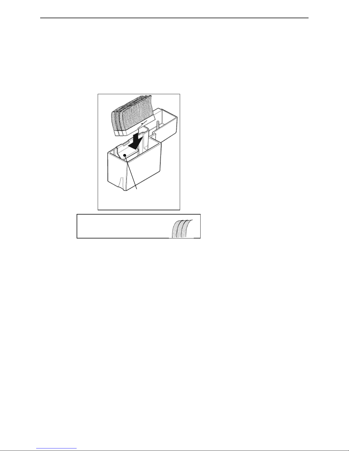
WASHING THE TANK, BRUSHES, AND BOTTLE
Water Brushes: Glue from the tape may accumulate and reduce the effectiveness of the moistening
system. Wash brushes weekly with mild soap.
To remove any old dried adhesive, you will need to tilt the brushes to clear the retaining bracket. Be sure
to replace the brushes in the tank correctly. See Figure 17. Facing the brushes in the wrong direction can
result in poor moistening and tape jamming.
The brush tips are cut at an angle and in 3 unique lengths.
They are designed to be used in one direction only.
WARNING: Never cut the ends of the brush tips to remove dried
glue ... the brush will be too short and will not work properly.
FIGURE 17 - Inserting Brushes into the Tank
Maintenance
24
Page 25

Better Packages Section 4
Brushes must be angled toward the
!
At first, tilt the brush toward the dispenser so that the head of the cotter pin clears the retaining bracket as
you push the brushes into the tank.
Then, tilt the brush back so that it seats flatly on the bottom of the tank.
CLEANING THE SHEAR BLADES
For the dispenser to cut the tape well, blades need to be free of adhesive, dust etc. These materials need
to be cleaned from the blade.
SUGGESTED PREVENTATIVE MAINTENANCE SCHEDULE:
Weekly
• Wash water brushed with mild soap; rinse well.
• Clean any accumulated tape dust with a dry brush or blower.
• Wash water tank with mild soap; rinse well.
Monthly
• Clean accumulated glue from blades using a scraper.
(Don’t scrape the cutting edge, the blade may dull and need replacement).
Caution: The blade is sharp and can cut easily, be careful working around it.
• Apply light coating of light machine oil to back of blade.
• Add a few drops of light machine oil to felt pads.
Annually
• Thoroughly clean all accumulated pieces of tape, tape dust and any other foreign material from inside
the machine with dry brush or blower.
• Clean bottom of heaters and pressure plates of accumulated glue.
• Oil upper and lower blades lightly with light machine oil.
• Clean all covers with damp rag.
WARNING: Be sure the dispenser is OFF before performing any
cleaning operations.
front of the dispenser in order to work.
Shorter brushes go in the back.
Installing the brushes backwards will
cause a troublesome tape jam
Maintenance
25
Page 26

Better Packages Section 4
FIGURE
19 – Moving Shear
Maintenance
CLEARING JAMS
If the tape jams inside the dispenser near the cutting blade, proceed as follows:
1. Turn the dispenser OFF and UNPLUG it. See Figure 18.
2. Cut the tape roll just behind the upper tape plate to get it out of your way.
3. Remove the upper tape plate.
4. Raise the shear blade by moving the lever located to the right of the feed wheel forward. See Figure
19.
FIGURE 18 – On/Off Switch Location
Blade into View
26
Page 27

Better Packages Section 4
FIGURE
20 -
Installing the
Shear
Feed the tape:
Shear
Blade
FIGURE
21 -
Feeding the Tape
Black
Roller
Maintenance
5. Pull out any jammed tape. Push the lever back to lower the shear blade to its normal operating
position.
6. Swing the heater assembly up out of the way and check for and clear any jams in front of the shear
blade.
7. Replace the upper tape plate and feed the tape back into position when you have cleared the jam.
See Figures 20 and 21.
Upper Tape Plate
Blade
Upper Tape Plate
• Over the Rubber Roller
• Under the Upper Tape Plate
• Under the Guide Bar
• Up Against the Shear Blade
CHANGING THE FUSE
If the dispenser is plugged in but doesn’t work, it is probably the safety interlock switch. The safety interlock
switch makes contact when the top cover is properly closed. Before performing any other diagnostic checks,
ensure that the top cover is fully closed and that the switch is activated when the cover is closed. If the top cover
is properly closed and the on/off switch doesn’t light in the “ON” position, it may indicate a blown fuse.
Proceed as follows:
1. Unplug the dispenser’s power cord from the wall.
2. Determine if the outlet is OK. Test the outlet with a light or other device.
3. If the outlet is OK, remove the fuse holder from the electrical panel at the rear of the dispenser and
check the fuse to see if it is blown. A break in the filament (the thin wire running the length of the fuse)
indicates the fuse is blown. See Figure 22. Use a continuity tester to check the fuse if you are unsure.
27
Page 28

Better Packages Section 4
FUSE (A break in the
Maintenance
filament indicates the
fuse is blown.)
FIGURE 22 - Fuse Holder Location
• If the fuse is blown, replace it with one rated at AL T2 250V.
• If the fuse is OK and the system is still not working, contact your dealer for
service or call Better Packages for assistance at:
1-800-237-9151 (in the US only) or 1-203-926-3700 (outside of the US)
LUBRICATION
The blade oiler is a felt pad that presses lightly on the back of the shear blade.
1. Turn the dispenser off and unplug it.
2. Pull back gently on the blade oiler to move it away from the shear blade.
3. Keep the felt pad slightly moist by adding several drops of light machine oil at regular weekly or
monthly intervals depending on use. Do not over-oil. The oil will keep your shear blade lubricated for
clean, fast cutting.
4. Gently push the oiler back into position next to the shear blade.
5. Plug the dispenser back in.
Blade Oiler
(Pushed away from shear blade)
FIGURE 23 - Blade Oiler Location
28
Page 29

Better Packages Section 4
!
NOTE: All other moving parts of the machine are permanently lubricated and SHOULD NOT BE
LUBRICATED. Putting oil or grease on the oilite bearings clogs them up and makes them wear
prematurely.
CLEANING
Inside the dispenser:
• Brush out paper dust
• Do Not use spray cleaners
Exterior surface of the dispenser:
• Use a mild soap and water
• No ammonia based cleaning agents or solvents
CAUTION: Do not oil the feed roller shaft
WARNING: DO NOT USE SPRAY LUBRICANTS, SPRAY
CLEANER OR OTHER FLAMMABLE LIQUIDS, ON OR INSIDE
THIS TAPE DISPENSER.
Maintenance
29
Page 30

Better Packages Section 5
CHARACTERISTIC
MEASUREMENT
Specifications
MODEL DESCRIPTIONS
The Better Packages Model 555 is available in four variations.
• Standard models are available with either long or short lengths on their keypads.
BP555eS Standard Short Length
BP555eL Standard Long Length
• Automatic models are also available with either long or short lengths on
their keypads.
BP555eSA Automatic Short Length
BP555eLA Automatic Long Length
The difference between Automatic and Standard models is the capability for the Automatic models to
dispense the next piece of tape automatically each time a piece is removed. A repeating pattern of up to
three different lengths can be automatically dispensed with this feature. The lengths of these pieces can
be standard keypad button lengths or lengths adjusted using the , the , and buttons.
Additionally, Automatic mode allows the preset of two lengths using both
REPEAT 2
ENTER
REPEAT
START
and
TECHNICAL SPECIFICATIONS
Dispenser performance, capacities, dimensions, and weight are listed in the following table:
NOTE: Metric equivalents are shown in parentheses ( ) following the English measurements.
Tape Width 1.5” – 3.0” (3.8 cm – 7.7 cm)
Maximum Tape Roll
Diameter
Tape Lengths Dispensed Short Models (auto & std.) 6” to 45” (15 cm – 114 cm)
Dispensing Speed 45 inches per second (114 cm per second)
Number of Brushes 3
Water Bottle Capacity 34 oz (1 liter)
Shipping Weight 32 lbs (15 kgs)
Dimensions (L x W x H) 20” x 12.5” x 12” (51cm x 32cm x 30cm)
Power Requirements
555eS, eSA, eL, eLA
555eM, eMA
555eJ, eJA
NOTE: Models produced for the Metric market may have keypads with different lengths than those shown in the
above table.
10” (25 cm)
Long Models (auto and std.) 12” to 90” (30 cm – 228cm)
115V 60Hz, 4 Amps
230V 50/60Hz, 2 Amps
100V 50/60Hz, 4 Amps
PORT CONNECTIVITY
The 9-pin female connector at the rear of the dispenser is an Input/Output port (I/O) allowing the
communication with optional devices such as the AMD-1, an Automatic Carton Measuring Device.
• On standard models, this I/O port is active for use with pedal foot switches or other similar devices
which use the “contact closure” method of sending a signal.
• On automatic models, this I/O port also provides access to the dispenser’s RS-232C serial data port.
Pedal foot switches or other “contact closure” devices may still be used on automatic models.
CONNECTOR CONFIGURATIONS
Both standard and automatic models are equipped with 9-pin female D-type connectors.
30
Page 31

Better Packages Section 5
MODEL TYPES
Model Length, Unit
of Measure
BP555e S Short, Inch 115V 60Hz US/Canada (1)
BP555e SA Short, Inch 115V 60Hz US/Canada (1)
BP555e L Long, Inch 115V 60Hz US/Canada (1)
BP555e LA Long, Inch 115V 60Hz US/Canada (1)
BP555e M Metric 230V 50Hz Europe (2)
BP555e MA Metric
BP555e J Metric
BP555e JA Metric
BP555e F Short, Inch 230V 50 Hz Far East (1)
BP555e FA Short, Inch 230V 50Hz Far East (1)
1) Tape gummed side in, (2) Tape gummed side out
Voltage Country
Continent Used
230V 50Hz Europe (2)
100V 50/60 HZ Japan (1)
100V 50/60 HZ Japan (1)
Specifications
31
Page 32

Better Packages
Index
Better Packages, Inc.
Warranty Information
The manufacturer warrants each new Better Packages machine and accessory to be free from defects in material
and workmanship under normal and proper use. Its obligation under this warranty being limited to replacing or
repairing any defective parts within the time period indicated for the specific model after delivery (at the company’s
discretion) to the customer. Wearable parts such as shear blades, water bottles and caps, water brushes and motor
brushes are not covered under the warranty. Machines used for any reason not intended by the manufacturer will not
be considered for warranty protection.
The company will replace or repair (at the company’s discretion) any defective parts within the warranty period, on a
no-charge basis. The Authorized Distributor/Service Center will furnish, without charge, within the time period
indicated for the specific model, necessary labor to service the machine.
If customer wishes, they may forward any machine listed below with authorization from Better Packages or an
Authorized Distributor/Service Center for warranty service. Any item shipped for warranty service must be shipped in
the original factory carton and properly packed with the original protective packaging inserts or a secure carton that
will properly protect the unit during transit. Units received improperly packed are subject to costs associated with
damage caused during transit. These costs will be the responsibility of the customer. All associated shipping or
freight costs related to items shipped for service are the sole responsibility of the customer.
For service under this warranty, call or write your nearest Better Packages Distributor/Service Center or Better
Packages, Inc. Ansonia, CT at 800-237-9151 (US only) or (203) 926-3700. To locate your local Authorized
Distributor/Service Center, visit www.betterpackages.com. Transportation charges on machines or parts returned
to Better Packages for service must be prepaid by the customer. Customers will be responsible for freight expenses
on parts or machines returned to them.
Better Packages’ ship-to address is: 4 Hershey Drive
Ansonia, Connecticut 06401
Product Warranty*
Model Parts Labor
Better Pack® 755e Series
Better Pack® 555e Series
Better Pack
®
500 Series 2 Years 6 Months
2 Years 6 Months
2 Years 6 Months
Better Pack® 333 Series 2 Years 6 Months
TapeShooter® 404 2 Years 6 Months
Packer® 3S 2 Years 6 Months
Better Pack® PS2A 1 Year 6 Months
*When servicing a Better Packages product, genuine Better Packages replacement parts should be used. Any
other parts used will void all existing warranties along with UL, CE and CSA certifications and may create a safety
hazard.
This warranty statement dated May 1, 2014 supersedes all other prior published statements.
32
Page 33

Better Packages
Index
A
Address....................................................................................................................................... 2
Adjust the Setting on the Heater Assembly. .............................................................................. 12
Adjusting the Amount of Water Applied to the Tape .................................................................. 22
Adjusting the Roll Guides ............................................................................................................ 5
Advantages of Water Activated Tape ........................................................................................ 20
Applying Tape to the Carton ...................................................................................................... 23
Attaching the Power Cord ......................................................................................................... 10
B
Better Packages Warranty Statement ....................................................................................... 32
C
Changing the Fuse .................................................................................................................... 27
Checking the Contents ................................................................................................................ 5
Checking Upper Tape Plate ........................................................................................................ 7
Choosing the Best Tape for Your Application ............................................................................ 20
Choosing the Correct Tape Length ........................................................................................... 23
Cleaning the Shear Blades ....................................................................................................... 25
Clearing Jams ........................................................................................................................... 26
D
Different Grades of Sealing Tape .............................................................................................. 21
F
Fill Out the Warranty Card .......................................................................................................... 5
I
Identifying the Types of Tape .................................................................................................... 20
Installing the Bottle and Water Tank ............................................................................................ 8
L
Loading the Tape ........................................................................................................................ 6
Lubrication ................................................................................................................................ 28
M
Model Descriptions ................................................................................................................... 30
Mounting to a Work Bench ........................................................................................................ 10
P
Port Connectivity ....................................................................................................................... 30
Power Cord, Attaching .............................................................................................................. 10
Preparing the Unit for Operation ................................................................................................. 5
Proper Tape Moistening ............................................................................................................ 22
33
Page 34

Better Packages
Index
S
Select the Tape Length (Automatic Model) ............................................................................... 14
Select the Tape Length (Standard Model) ................................................................................. 13
Selecting Tape .......................................................................................................................... 21
T
Technical Specifications ............................................................................................................ 30
To Activate Automatic Mode ..................................................................................................... 18
To Adjust the Length of a Number Button then Double It .......................................................... 16
To Dispense a Length of Tape Twice the Length ...................................................................... 16
To Dispense a Random Length of Tape .................................................................................... 14
To Dispense a Specific Length of Tape Not on a Number Button .............................................. 15
To Dispense Tape Longer than the Amount on a Number Button ............................................. 15
To Dispense Tape Shorter than the Amount on a Number Button ............................................. 15
To Repeat One Tape Length Automatically ............................................................................... 18
To Repeat the Length Previously Dispensed (Standard Model) ................................................ 17
To Repeat the Length Previously Dispensed (Automatic Model) ............................................... 17
To Repeat Three Tape Lengths Automatically .......................................................................... 19
To Repeat Two Tape Lengths Automatically ............................................................................. 18
Turn the System “ON” ............................................................................................................... 12
U
Unpacking ................................................................................................................................... 5
W
Washing the Tank, Brushes, and Bottle .................................................................................... 24
What You Should Know About Adhesive Formulas ................................................................... 21
34
Page 35

Better Packages
Maintenance Notes
___________________________________________________________________________________
___________________________________________________________________________________
___________________________________________________________________________________
___________________________________________________________________________________
___________________________________________________________________________________
___________________________________________________________________________________
___________________________________________________________________________________
___________________________________________________________________________________
___________________________________________________________________________________
___________________________________________________________________________________
___________________________________________________________________________________
___________________________________________________________________________________
___________________________________________________________________________________
Better Packages
Service Dates
_________________________________________ _______________________________________
_________________________________________ _______________________________________
_________________________________________ _______________________________________
_________________________________________ _______________________________________
_________________________________________ _______________________________________
_________________________________________ _______________________________________
_________________________________________ _______________________________________
_________________________________________ _______________________________________
_________________________________________ _______________________________________
_________________________________________ _______________________________________
35
 Loading...