

iProSecu iDC-453 User Manual
1/44
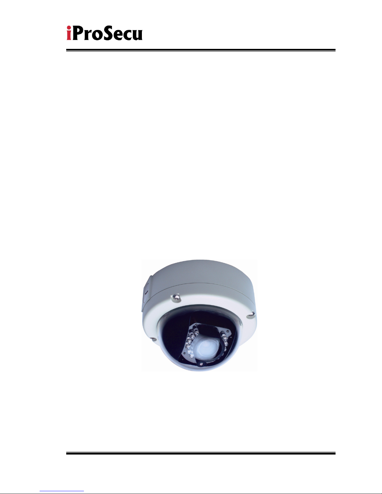
User Manual
CMOS 2.0 Mega Pixel
IP Vandal Dome Camera
2/44
WARINGS
TO REDUCE THE RISK OF FIRE OR ELECTRIC SHOCK, DO NOT EXPOSE THIS
PRODUCT TO RAIN OR MISTURE.
DO NOT INSERT ANY METALLIC OBJECT THROUGH VENTILATION GRILLS.
CAUTION
CAUTION
RISK OF ELECTRIC SHOCK
DO NOT OPEN
CAUTION:TO REDUCE THE RISK OF ELECTRIC SHOCK.
DO NOT REMOVE COVER (OR BACK).
NO USER-SERVICEABLE PARTS INSIDE.
REFER SERVICING TO QUALIFIED SERVICE PERSONNEL.
COPYRIGHT
THE TRADEMARKS MENTIONED IN THE MANUAL ARE LEGALLY REGISTERED
TO THEIR RESPECTIVE COMPANIES.

3/44
Content
I. PREFACE ....................................................................................................................................... 4
II. PRODUCT SPECIFICATIONS ....................................................................................................... 4
III. PRODUCT INSTALLATION ........................................................................................................... 7
A. M
ONITOR SETTING
..................................................................................................................................... 7
B. H
ARDWARE INSTALLATION AND
I/O P
IN ASSIGNMENT
............................................................................... 8
C. IP A
SSIGNMENT
....................................................................................................................................... 13
D. I
NSTALL ACTIVEX CONTROL
: ................................................................................................................... 15
IV. LIVE VIDEO .................................................................................................................................. 17
V. CONFIGURATION ........................................................................................................................ 20
A. S
YSTEM
.................................................................................................................
錯誤
錯誤錯誤
錯誤
!
尚未定義書籤
尚未定義書籤尚未定義書籤
尚未定義書籤。。。。
B. N
ETWORK
................................................................................................................................................ 24
C. A/V S
ETTING
........................................................................................................................................... 28
D. E
VENT LIST
.............................................................................................................................................. 34
VI. NETWORK CONFIGURATION .................................................................................................... 41
VII. FACTORY DEFAULT.................................................................................................................... 43
VIII. PACKAGE CONTENTS ............................................................................................................... 44
APPENDIX I .......................................................................................................................................... 44
V1.1_111114

4/44
I. Preface
3-AXIS IP Vandal Dome is a professional CMOS Mega Pixel IP Vandal Dome. It
has built-in web server which enables user to view real-time video via IE browser.
It also supports simultaneously H.264/JPEG/ MPEG4 (3GPP Only) video
compression with CMOS M-Pixel Sensor which provides smooth and high video
quality. The video can be stored in the SD card, and can be playback remotely.
3-AXIS IP Vandal Dome is an easy-to-use IP Camera which is designed for
security application.
II. Product Specifications
IP66
2M CMOS Sensor
Power over Ethernet available
IR LED Built-in 12M
Vandal-proof 400 Pounds
H.264/ JPEG/ MPEG4 (3GPP only) compression
SD card backup
2-way audio
Support Cell Phone/PDA/3GPP
3 Streaming
SDK for Software Integration
Free Bundle 36 ch recording software
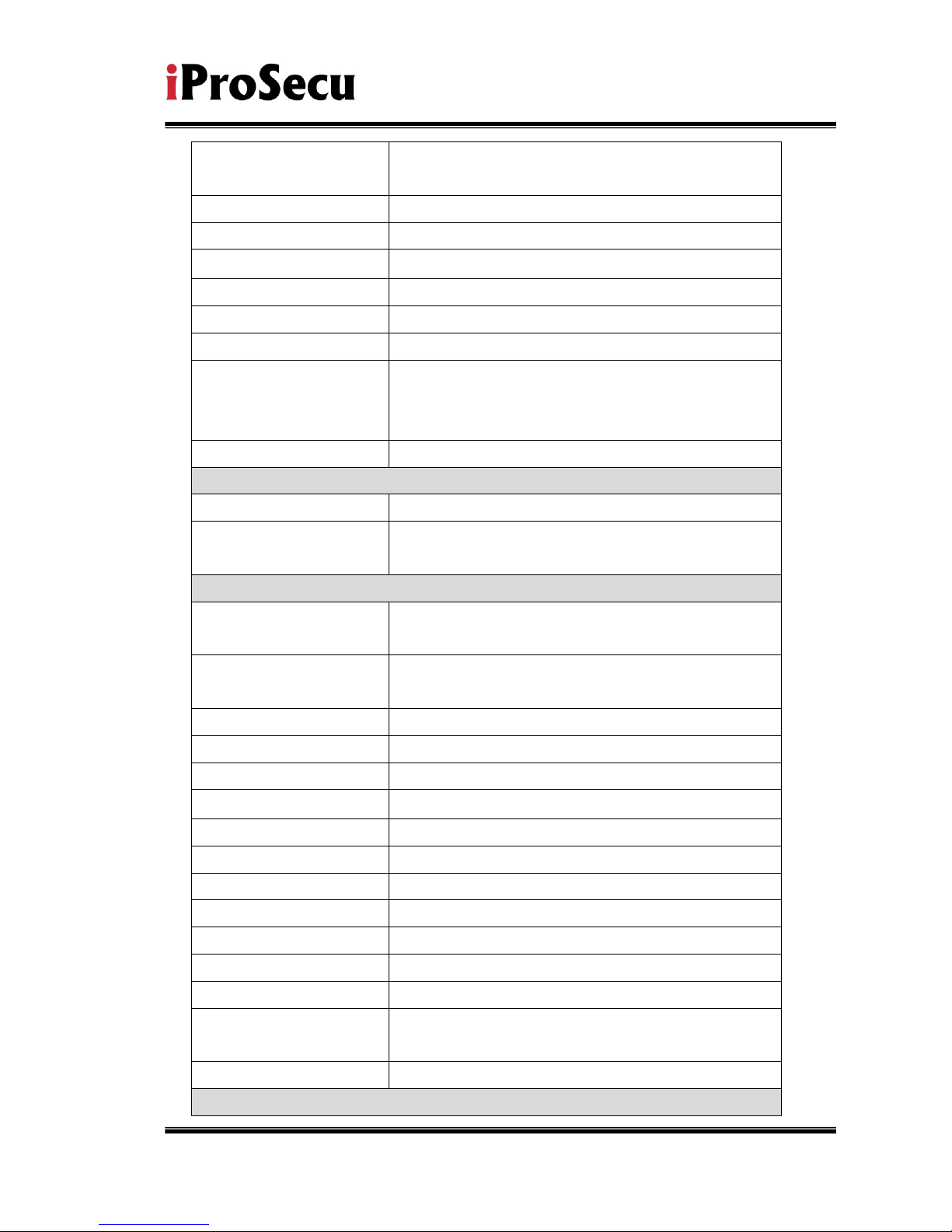
Specifications
Hardware
CPU ARM 9,32 bit RISC
DDR2 256MB
Flash 16M
Image sensor 1/3” CMOS (2M-Pixel)
Lens Type Vari-focal 2.7~9mm Mega Pixel Lens
ICR
Mechanism IR Cut Filter(optional)
5/44
LED Built-in 18 IR LED (optional)
IR Distance-12M (Optional)
I/O 1i
n/1 relay out
Video Out 1 Vp-p, 75 Ohms
MIC in 1
Audio Out 1
Power Over Ethernet Yes
Power Consumption DC 12V, 560mA
3-Axis Gimbal
Adjustments Angle
Pan: 175∘
Tilt 75∘
Rotation 180∘
Dimensions 126mm (W) x 126mm (L) x 100mm (D)
Network
Ethernet 10/ 100 Base-T
Network Protocol HTTP, TCP/ IP, UDP, SMTP, FTP, PPPoE,
DHCP, DDNS, NTP
System
Video Resolution 1600x1200,1280x1024, 1280x960, 1280x720,
800x600, 640x480, 320x240, 160x120
CMOS setting Night Mode, Brightness, Contrast, BLC,
Sharpness
Triple Streaming Yes
Image snapshot Yes
Full screen monitoring Yes
Privacy Mask Yes, 3 different areas
Compression format H.264/ JPEG/ MPEG4 (3GPP only)
Video bitrate adjust CBR, VBR
Motion Detection Yes, 3 different areas
Triggered action Mail, FTP, Save to SD card, Relay
Pre/ Post alarm Yes, configurable
Security Password protection
Firmware upgrade HTTP mode, can be upgraded remotely
Simultaneous
connection
Up to 10
Audio Yes, 2-way(Duplex Support)
SD card management
6/44
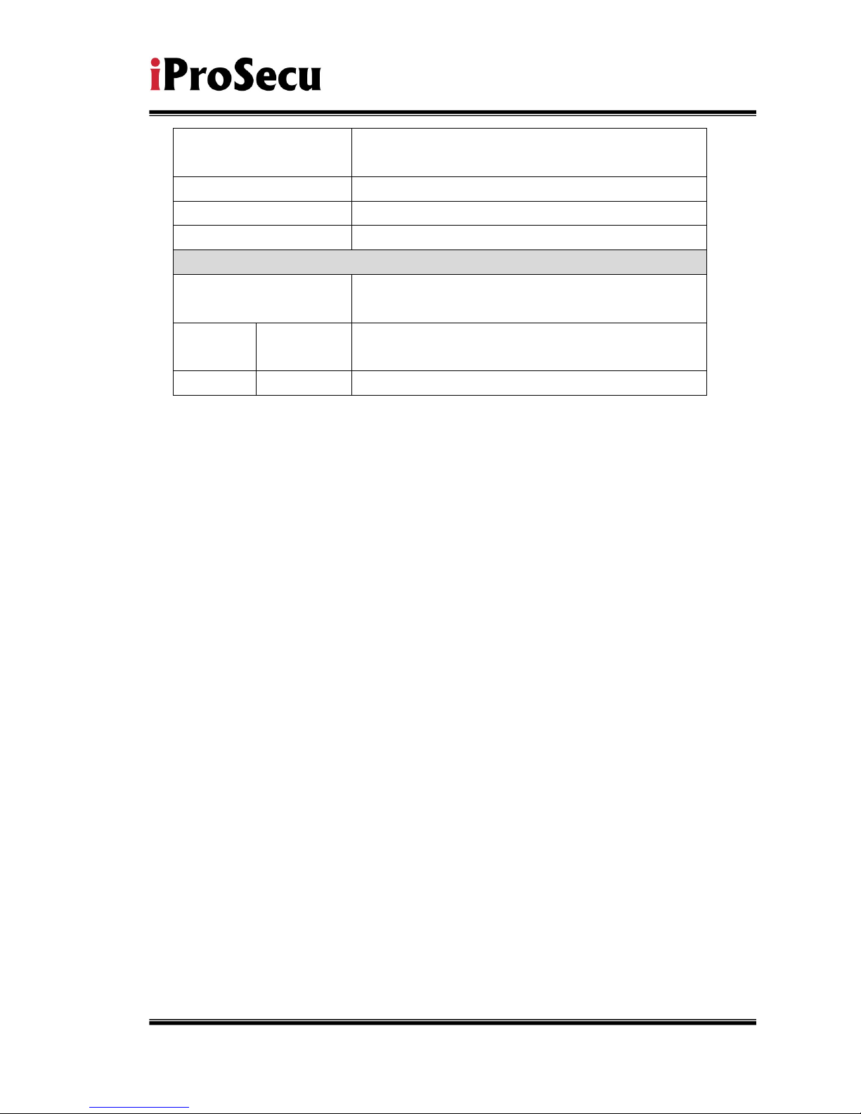
Recording trigger Motion Detection, IP check, Network Status (wire
Connection only), schedule, alarm
Video format AVI, JPEG
Video playback Yes
Delete files Yes
Web browsing requirement
OS Windows 2000, XP, 2003, Microsoft IE 6.0 or
above
Hardware Suggested
Intel Dual Core 1.66G,RAM: 1024MB, Graphic
card: 128MB
Minimum Intel-C 2.8G, RAM: 512MB, Graphic card: 64MB
7/44
III. Product Installation
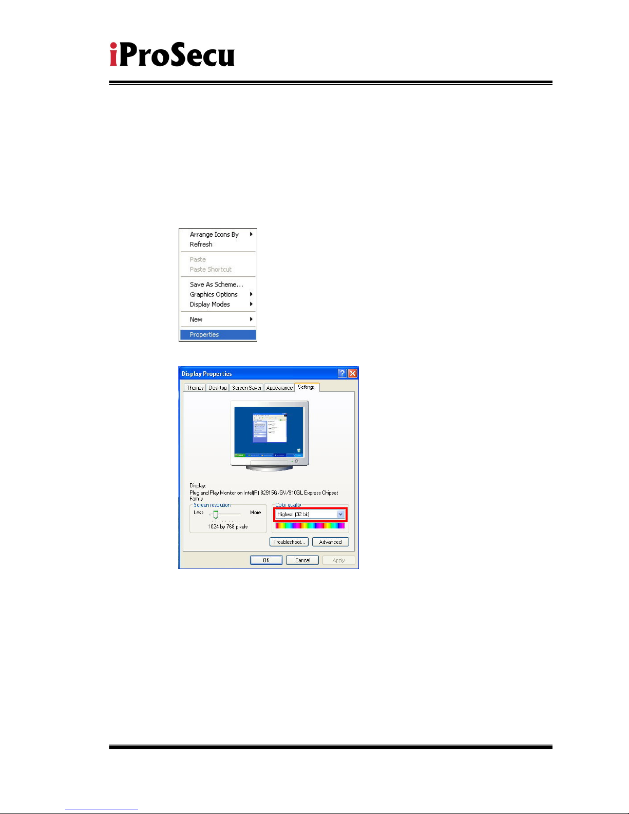
A. Monitor Setting
i. Right-Click on the desktop. Select “ Properties”
ii. Change color quality to highest (32bit).
8/44
B. Hardware Installation and I/O Pin
Assignment
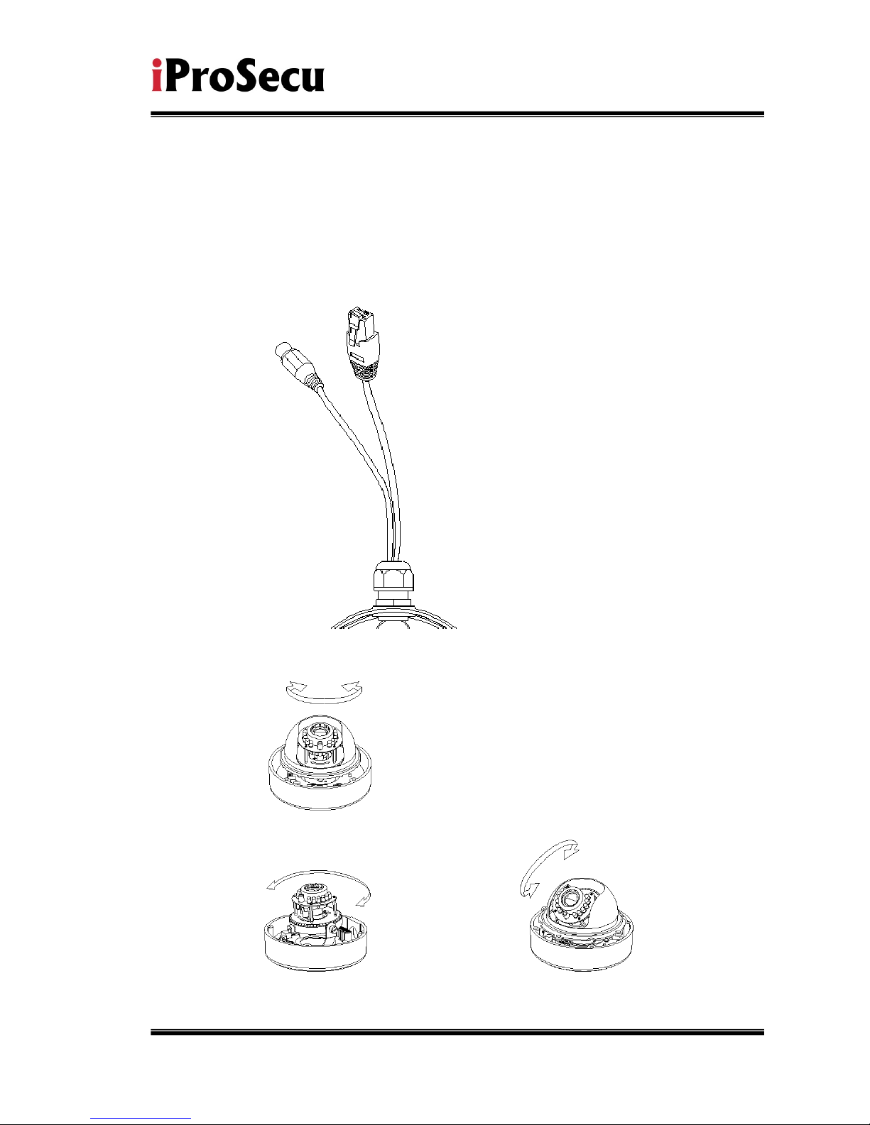
i. Connect a power adapter and IP Camera to PC or local network
ii. 3-Axis Gimbal Adjustments
Once the users open the case, the gimbal adjustment offers the
○
2 Tilt: 30°~90°
○
1 Pan: 172°
○
3 Rotation: 180°
9/44
convenience method to install on the wall. The pan, tilt, and rotation are
provided in this model. The users can adjust the gimbal with Pan 172
degree, tilt 30~90 degree, and rotation 180 degree respectively.
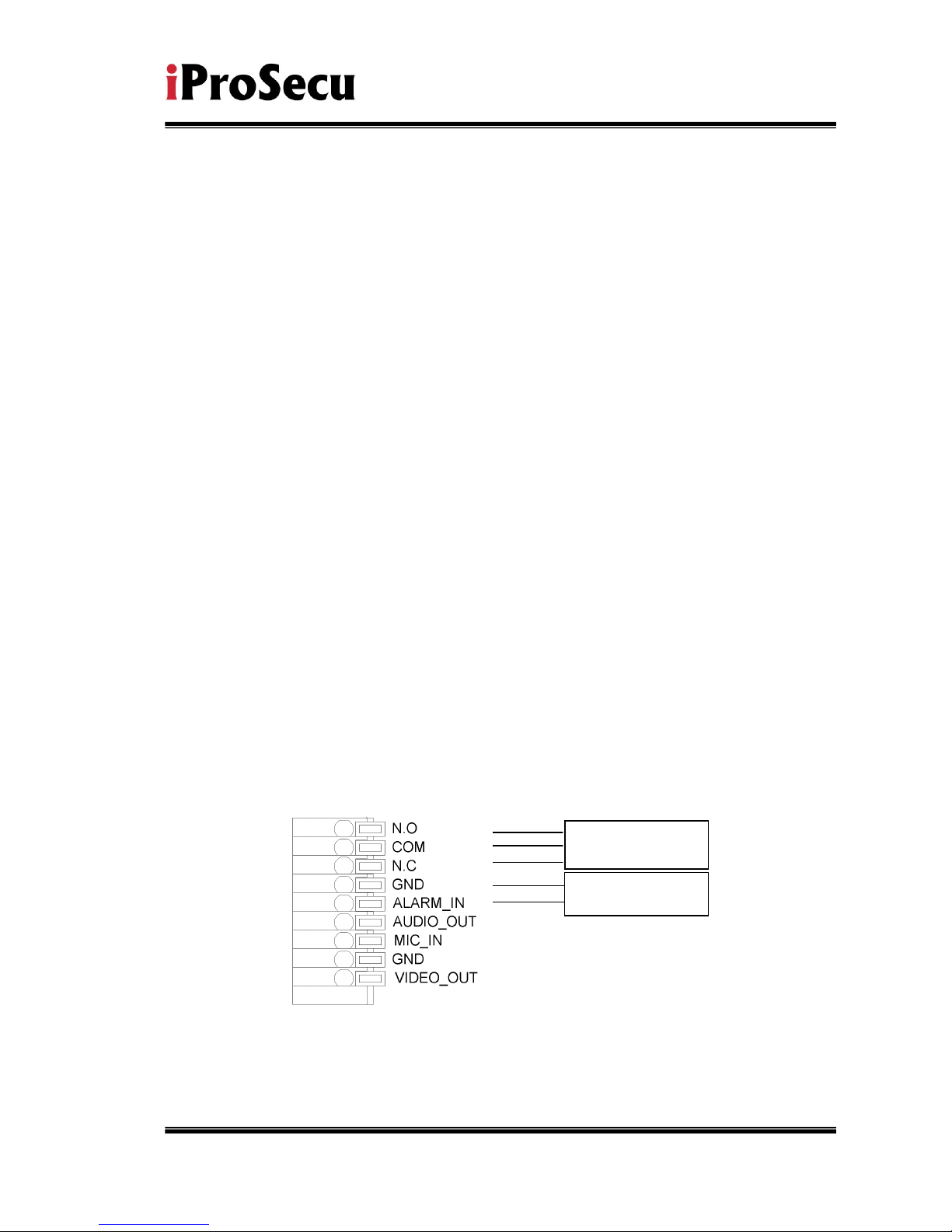
iii. I/O Control Instruction
I/O terminal connector – used in application, for e.g., motion detection, event
triggering, alarm notifications. It provides the interface to:
1 Digital Input (GND+Alarm) – An alarm input for connecting devices that can
toggle between an open and closed circuit, for example: PIRs, door/window
contacts, glass break detectors, etc. When a signal is received the state changes
and the input becomes active.
Relay output (COM +N.O.) / (COM+N.C.) – An output to Relay switch, for
example: LEDs, Sirens, etc
iv. Digital Input
Alarm Input
1. GND (Ground) : Initial state is LOW
2. Alarm : Max. 50mA, DC 3.3V
Relay Output
1. N.C. (Normally Close): Max. 1A, 24VDC or 0.5A, 125VAC
2. COM: (Common)
3. N.O. (Normally Open): Max. 1A, 24VDC or 0.5A, 125VAC
ALARM IN
RELAY OUT

10/44
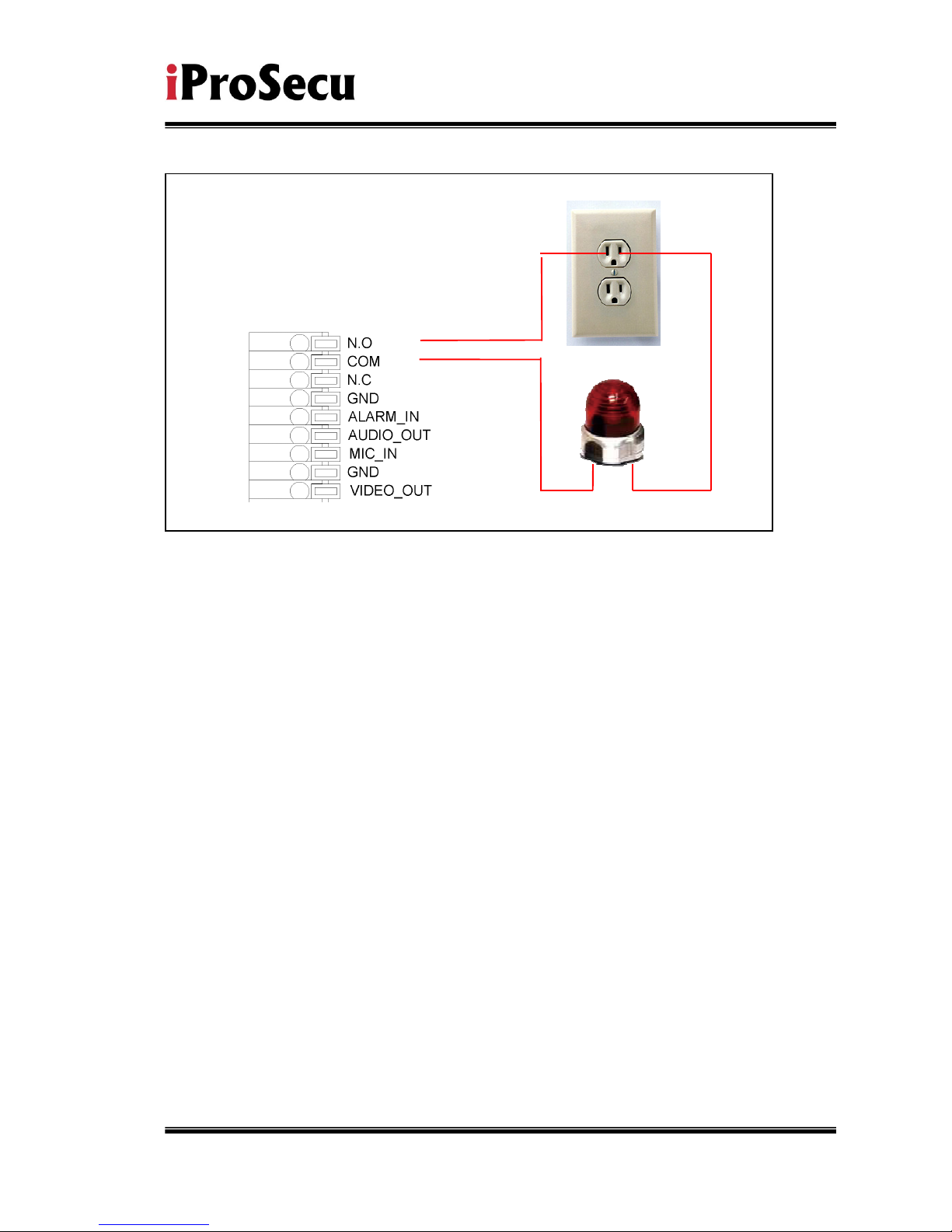
v. Relay
1. Digital Input connection
2. Relay Output Connection
Door/Window
Contacts
11/44
Or
12/44
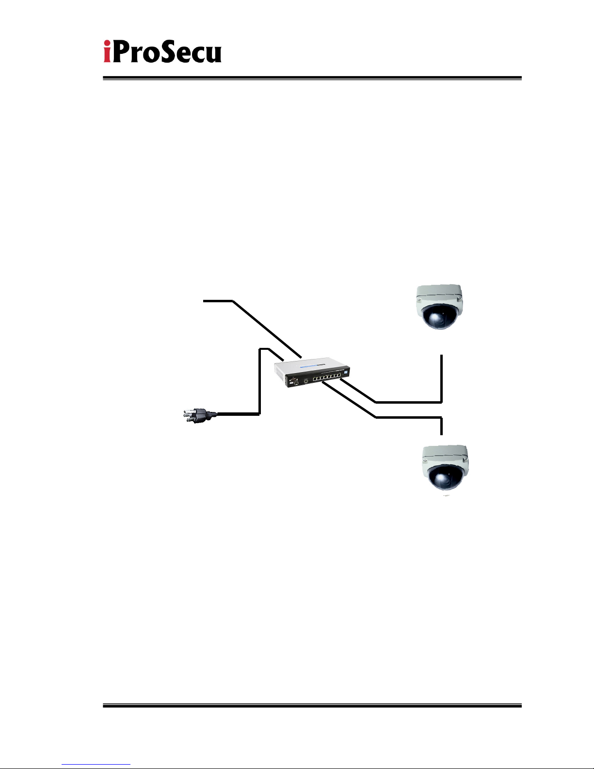
v. PoE ( Power Over Ethernet)(Optional)
802.3af, 15.4W PoE Switch is
recommended
Power over Ethernet (PoE) is a technology that integrates power into a
standard LAN infrastructure. It enables power to be provided to the
network device, such as an IP phone or a network camera, using the
same cable as that used for network connection. It eliminates the need
for power outlets at the camera locations and enables easier application
of uninterruptible power supplies (UPS) to ensure 24 hours a day, 7 days
a week operation.
Ethernet
PoE Switch
PoE IP Camera
PoE IP Camera
Ethernet Cable
Ethernet Cable
13/44
C. IP Assignment
i. Use the software, “IP Installer” to assign the IP address of IP CAMERA.
The software is in the attached software CD.
ii. IP installer supports two languages
a. IPInstallerCht.exe:Chinese version
b. IPInstallerEng.exe:English version
iii. There are 3 kinds of IP configuration.
a. Fixed IP (Public IP or Virtual IP)
b. DHCP (Dynamic IP)
c. Dial-up (PPPoE)
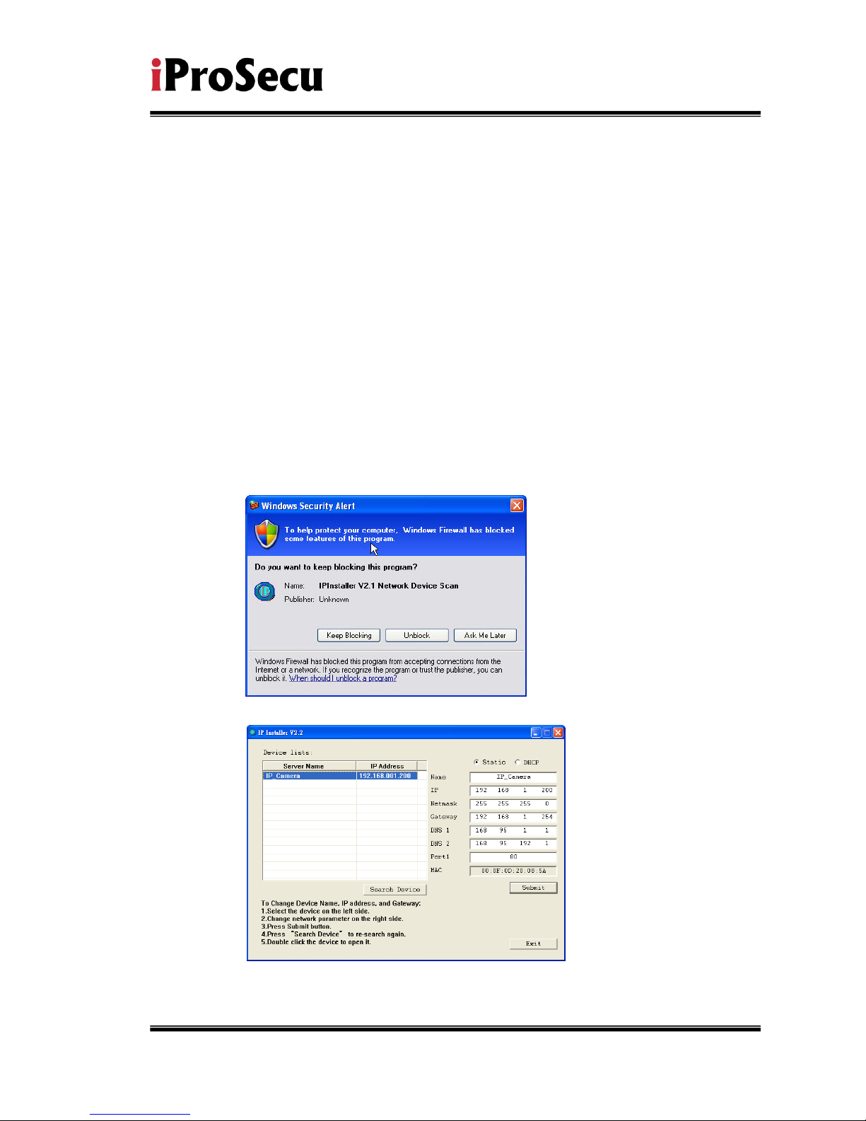
iv. Execute IP Installer
v. For Windows XP SP2 user, it may popup the following message box.
Please click “Unblock”.
vi. IP Installer configuration:
vii. IP Installer will search all IP Cameras connected on Lan. The user can
click “Search Device” to search again.

14/44
viii. Click one of the IP Camera listed on the left side. The network
configuration of this IP camera will show on the right side. You may
change the “name” of the IP Camera to your preference (eg: Office,
warehouse). Change the parameter and click “Submit” then click “OK”. It
will apply the change and reboot the Device.
ix. Please make sure the subnet of PC IP address and IP CAM IP address
are the same.
The same Subnet:
IP CAM IP address: 192.168.1.200
PC IP address: 192.168.1.100
Different Subnets:
IP CAM IP address: 192.168.2.200
PC IP address: 192.168.1.100
To Change PC IP address:
Control PanelNetwork ConnectionsLocal Area Connection
PropertiesInternet Protocol (TCP/IP) Properties
Please make sure your IP Camera and PC have the same Subnet. If not,
please change IP Camera subnet or PC IP subnet accordingly.
x. A quick way to access remote monitoring is to left-click the mouse twice
on a selected IP Camera listed on “Device list” of IP Installer. An IE
browser will be opened.
 Loading...